UNIT-1
OSCILLATIONS AND WAVES
Simple Harmonic Motion or SHM is defined as a motion in which the restoring force is directly proportional to the displacement of the body from its mean position. The direction of this restoring force is always towards the mean position.
Simple harmonic motion can be described as an oscillatory motion in which the acceleration of the particle at any position is directly proportional to the displacement from the mean position. It is a special case of oscillatory motion.
All the Simple Harmonic Motions are oscillatory and also periodic but not all oscillatory motions are SHM. Oscillatory motion is also called the harmonic motion of all the oscillatory motions wherein the most important one is simple harmonic motion (SHM).
In this type of oscillatory motion displacement, velocity and acceleration and force vary (w.r.t time) in a way that can be described by either sine (or) the cosine functions collectively called sinusoids.
Simple Harmonic Motion
When a particle moves to and fro about a fixed point (called equilibrium position) along with a straight line then its motion is called linear Simple Harmonic Motion.
For Example: spring-mass system
Conditions for Linear SHM:
The restoring force or acceleration acting on the particle should always be proportional to the displacement of the particle and directed towards the equilibrium position.
F∝−x
a∝−x
x – displacement of particle from equilibrium position.
F – Restoring force
A– acceleration
Let us consider a simplest mechanical system executing simple harmonic motion. We will solve differential equation for SHM.
Key Takeaways
- Simple Harmonic Motion or SHM is defined as a motion in which the restoring force is directly proportional to the displacement of the body from its mean position.
- Conditions for Linear SHM is given bythe restoring force or acceleration acting on the particle should always be proportional to the displacement of the particle and directed towards the equilibrium position.
- Mathematically condition is written as F∝−x
MECHANICAL SIMPLE HARMONIC OSCILLATORS
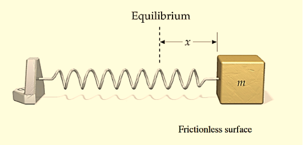
The figure-1 depicts simple mechanical oscillator having mass attached to the spring. This structure is similar to Pendulum. It is also known as harmonic oscillator.
|
Figure: 1 Simple Mechanical Oscillator
If a body attached to a spring is displaced from its equilibrium position, the spring exerts a restoring force on it, which tends to restore the object to the equilibrium position. This force causes oscillation of the system, or periodic motion.
When the restoring force is directly proportional to the displacement from equilibrium, the resulting motion is known as simple harmonic motion and the oscillator is known as Harmonic Oscillator.
In this type of system body itself changes its position.
For mechanical oscillation two things are especially responsible i.e. Inertia & Restoring force.
Differential Equation
A particle is said to be execute simple harmonic oscillation is the restoring force is directed towards the equilibrium position and its magnitude is directly proportional to the magnitude and displacement from the equilibrium position.If F is the restoring force on the oscillator when its displacement from theequilibrium position is x, then
F –x
–x
Here, the negative sign implies that the direction of restoring force is opposite to that of displacement of body i.e. towards equilibrium position.
F= -kx ............. (1)
Where, k= proportionality constant called force constant.
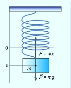
An example of such a simple system is the mass m, attached to a spring of stiffness k.
|
Figure 2: Simple Mechanical Oscillator
In the case of a mass on a spring, the restoring force for small oscillations obeys Hooke’s law:
F=−kx ………….(1)
where k is the stiffness of the spring. Here the coordinate x=0 corresponds to the point of equilibrium, in which the force of gravity is balanced by the initial tension of the spring.
Then, according to Newton’s second law
F= ma = m  ………….(2)
From equation (1) and (2)
m  = −kx
= −kx
m  + kx = 0
 +
+  x = 0 ………….(3)
Equation (3) can also be written as
⇒x′′+ x = 0
x = 0
 +ω2x = 0 ………….(4)
or
⇒x′′+ω2x=0
On comparing equation (3) and (4)
ω2 =
ω= ………….(5)
Solution of differential equation is
x= Acosωt ………….(4)
or
x = Acos
Thus, the mass on the spring will perform undamped harmonic oscillations with the circular frequency
ω=
The time period of oscillation, respectively, will be equal to
T= =2π
=2π
Phase
The form of Equations (4) implies that over each period of oscillation, as the time t increases its value bythe fixed amount T,the oscillator passes through a complete cycle of x values. Now, during such a cycle, thequantity 2πt/T (i.e. the argument of the sine and cosine functions) increases by 2π, and each additional incrementof 2π corresponds to another complete oscillation.
In this way the argument of the sine or cosine functionbehaves rather like an angle measured in radians, since that too would complete an additional cycle for eachincrease of 2π radians (or 360°). Of course, there’s not really any angle involved here since the motion is linearand the quantity 2πt/T has no units; what the argument of the periodic sine or cosine function tells us is the stagethat the moving particle has reached within its own cycle of oscillation. Nonetheless, the argument of theperiodic function is often referred to as the phase angle or simply the phase of the motion and is as likely to beexpressed in radians (or the corresponding number of degrees) as it is to be given as a unit less number.
A phase of 0 corresponds to the start of a cycle, a phase of 2π to the start of the next cycle, 4π the next, and soon. If the motion is halfway through the first cycle the phase is π.
|
Figure 3:Displacement time graph
Displacement as a function of time in SHM is given by
x(t)=Acos(2πt/T+φ)=Acos(ωt+φ)
where φ is the phase or phase angle.
The Velocity is given by
v(t)=−Aωsin(ωt+φ)=−vmaxsin(ωt+φ),wherevmax=Aω=A
The Acceleration is a(t)=−Aω2cos(ωt+φ)=−amaxcos(ωt+φ), where amax=Aω2=A
A similar analysis of other oscillatory system which execute Simple harmonic motion. a simple pendulum – leads to the following formula for the oscillation period:
T=2π
where L is the length of the pendulum, g is the acceleration of gravity.
In the case of a compound or physical pendulum, the period of oscillation is given by
T=2π
where I is the moment of inertia of the pendulum about the pivot point, m is the mass of the pendulum, a is the distance between the pivot point and the center of mass of the pendulum.
Example: oscillation of mass spring system, oscillation of fluid-column in a U-tube, oscillation of simple pendulum, rotation of eartharound the sun, oscillation of body dropped in a tunnel along earth diameter, oscillation of floating cylinder, oscillation of a circular ring suspended on a nail, oscillation of atoms and ions of solids, vibration of swings etc.
Key Takeaways
- Simple mechanical oscillator having mass attached to the spring.
- A particle is said to be execute simple harmonic oscillation is the restoring force is directed towards the equilibrium position and its magnitude is directly proportional to the magnitude and displacement from the equilibrium position.
- Differential Equation is given by x′′+ ω2x=0 and Solution of differential equation is given by x= Acosωt
- The mass on the spring will perform undamped harmonic oscillations with the circular frequencyω=

- The time period of oscillation will be equal to T=
 = 2π
= 2π 
The square root of −1, called i, is important in physics and mathematics for many reasons. Measurable physical quantities can always be described by real numbers. You never get a reading of I meters on your meter stick. However, we will see that when i is included along with real numbers and the usual arithmetic operations (addition, subtraction, multiplication and division), then algebra, trigonometry and calculus all become simpler. While complex numbers are not necessary to describe wave phenomena, they will allow us to discuss them in a simpler and more insightful way.
An imaginary number is a number of the form i times a real number. A complex number, z, is a sum of a real number and an imaginary number: z=a+ib.
The real and “imaginary” parts, Re(z)and Im(z), of the complex number z=a+ib: Re(z) =a ,Im(z) =b
Note that the imaginary part is actually a real number, the real coefficient of iin z=a+ib.
The complex conjugate, z*, of the complex number z, is obtained by changing the sign of i:
z∗=a−ib
Note that Re (z) = (z+z∗)/2and Im (z) = (z−z∗)/2i
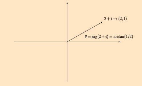
The complex plane: Because a complex number zis specified by two real numbers, it can be thought of as a two-dimensional vector, with components (a,b).
The real part of z, a=Re (z), is the xcomponent and the imaginary part of z, b=Im (z), is the ycomponent.
The absolute value, |z|, of z, is the length of the vector (a,b):
|z|= =z∗z
=z∗z
The absolute value |z|is always a real, non-negative number.
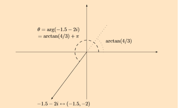
The diagrams in figures 4 and 5 show two vectors in the complex plane along with the corresponding complex numbers:
|
Figure 4 : A vector with positive real part in the complex plane.
The argument or phase, arg(z), of a nonzero complex number z, is the angle, in radians, of the vector (a,b)counter clockwise from the xaxis:
|
Like any angle, arg(z)can be redefined by adding a multiple of 2πradians or 360◦
|
Figure 5: A vector with negative real part in the complex plane
Describing Real Circling Motion in a Complex Way
Because the HO equation of motion is linear and homogeneous, linear combinations of solutions are also solutions. These linear combinations can be complex combinations.
We’ve seen that any complex number can be written in the form z=reiθ, where r is the distance from the origin, and θ is the angle between a line from the origin to z and the x -axis. This means that if we have a set of numbers all with the same r, but different θ ’s, such as reiα, reiβ, etc., these are just different points on the circle with radius r centered at the origin in the complex plane.
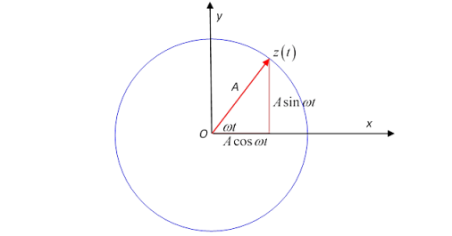
Now think about a complex number that moves as time goes on: z(t)=Aeiωt.
At time t, z(t) is at a point on the circle of radius A at angle ωt to the x -axis. That is, z(t) is going around the circle at a steady angular velocity ω. We can also write this:
z(t)=Aeiωt=Acosωt+iAsinωt
and see that the point z=x+iy is at coordinates (x,y)=(Acosωt,Asinωt).
|
Figure 6: Describing Real Circling Motion in a Complex Way
The angular velocity is ω, the actual velocity in the complex plane is dz(t)/dt.
Let’s differentiate with respect to time:
 (Aeiωt)=
 A(cosωt+isinωt)
=iωAeiωt
=iωA(cosωt+isinωt)
=iωAcosωt−ωAsinωt.
Now the x and y components of this velocity regarded as a vector. We will See that it is perpendicular to the position vector.
This differential equation has real and imaginary parts on both sides, so the real part on one side must be equal to the real part on the other side, and the same for imaginary parts. That gives
 cosωt=−ωsinωt,
  sinωt=ωcosωt
so differentiating the exponential is consistent with the standard results for trig functions. Differentiating one more time,
 Aeiωt=−ω2Aeiωt
Again going to the picture of a complex numbers as a two-dimensional vector, this is just the acceleration of an object going round in a circle of radius Aat angular velocity ω, and is just Aω2 towards the center of the circle, the familiar rω2=v2/r. Thinking physics here, this is the motion of an object subject to a steady central force.
PHASOR REPRESENTATION OF SIMPLE HARMONIC MOTION
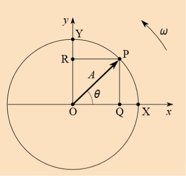
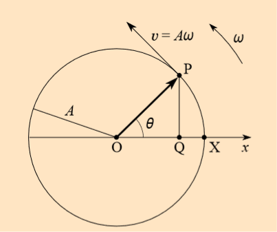
We have seen that a uniform circular motion can be associated with one-dimensional SHM. In this association adiameter of the circle is taken as the x-axis, and the SHM appears as the x-component of the motion around thecircle. Sometimes the SHM is described as the projection of the circular motion along the diameter. The reasonwhy this is useful is that it gives a clear visual representation of the three characteristics which define anySHMthe amplitude, the frequency and the phase.
The amplitude corresponds to the radius of the circle, thefrequency to the number of rotations of the object around the circle in unit time and the phase to the angle θbetween the x-axis and the line joining the centre of the circle to the position of the rotating object at the timeconcerned. In fact, this simple geometrical construction is even more useful than we have shown so far.
This new representation is called thephasor model and is illustrated inFigure 7.
Figure 7 has much in common withFigure 8 though a y-axis has beenadded for later convenience.
Where Figure 8 depicted uniform circular motion. Nonetheless, the main difference isone of terminology in that thedisplacement vector  of thecircular motion will henceforth bereferred to as the displacementphasor of the simple harmonicmotion. The length of the phasor, A,is called its amplitude while the angle θ between the phasor and the x-axisis called its phase.
In principle we can now describe a given SHM in termsof its associated (rotating) displacement phasorwe need not think aboutcircular motion at all. Phasor diagrams similar to Figure 7 can be drawn to represent the displacement, velocity,or acceleration of the oscillating object at any given timethat is to give the amplitude and phase of thedisplacement, velocity, or acceleration at that time.
|
Figure 7: The phasor model for one-dimensional SHM.
|
Figure 8: An object in uniform circular motion with an orbit radius A, an angular speed ω and an orbital speed v = Aω.
But what if we just equate the real parts of both sides? That must be a perfectly good equation: it is
 Acosωt=−ω2Acosωt
This is just the x -component of the circling motion, that is, it is the “shadow” of the circling point on the x-axis.
Forgetting for the moment about the circling point, and staring at just this x -axis equation, we see it describes the motion of a point always having acceleration towards the origin (that is, the minus sign ensures the acceleration is in the opposite direction to that of the point itself from the origin) and the magnitude of the acceleration is proportional to the distance of the point from the origin.
In fact, motion of this kind is very common in nature! It is called simple harmonic motion.
Key Takeaways
- complex number is given by z=a+ib and the complex conjugate is given by, z* =a−ib
- The absolute value, |z|, of z, is the length of the vector (a,b):|z|=

- The absolute value |z|is always a real, non-negative number.
- The SHM is described as the projection of the circular motion along the diameter. This gives a clear visual representation of the three characteristics which define anySHMthe amplitude, the frequency and the phase.
Definition- A system is said to execute free oscillations if on being disturbed from its position of equilibrium, it oscillates itself without outside interference
When a simple pendulum is displaced from its position of equilibrium and left to itself, it starts oscillating with a definite time period depending upon its length and the acceleration due to gravity. This is called free oscillations.
In free oscillation amplitude and period remains constant without any external. Ideally, free oscillation does not undergo damping but practically it is not possible. As in all-natural systems damping is observed unless and until any constant external force is supplied to overcome damping.
Let us discuss the case of simple pendulum and find out the natural frequency of oscillation for simple pendulum.
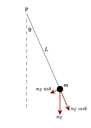
A simple pendulum consists of a ball or a point-massm hanging from a string of length L and fixed at a pivot point P. string by which ball is hanged should be massless.
|
Figure 9:Simple Pendulum
Let us suppose the ball or mass m isdisplaced to an initial angle and released, the pendulum will swing back and forth with periodic motion.
By applying Newton's second law for rotational systems,
 =
= …………..(1)
The equation of motion for the pendulum may be obtained
So the differential equation of motion for simple pendulum is written as
If the amplitude of angular displacement is small enough, so the small angle approximation Sinθ The equation of motion reduces to the equation of simple harmonic motion
The solution of differential equation is given by
where θo is the initial angular displacement, The frequency with which simple pendulum oscillate is given by
and ω=√g/L is called natural frequency of the motion. The period of this system (time for one oscillation) is given by
|
The period of a pendulum does not depend on the mass of the ball, but only on the length of the string. Two pendula with different masses but the same length will have the same period. Two pendula with different lengths will different periods; the pendulum with the longer string will have the longer period.
With the assumption of small angles, the frequency and period of the pendulum are independent of the initial angular displacement amplitude. A pendulum will have the same period regardless of its initial angle.
When the angular displacement amplitude of the pendulum is large enough that the small angle approximation no longer holds, then the equation of motion must remain in its nonlinear form
|
Key Takeaways
- A system is said to execute free oscillations if on being disturbed from its position of equilibrium, it oscillates itself without outside interference
- A simple pendulum consists of a ball or a point-mass m hanging from a string of length L and fixed at a pivot point P. string by which ball is hanged should be massless.
- The frequency with which simple pendulum oscillate is given by ω=√g/L is called natural frequency of the motion.
- The period of this system (time for one oscillation) is given by
|
- The period of a pendulum does not depend on the mass of the ball, but only on the length of the string.
We have seen that the total energy of a harmonic oscillator remains constant. Once started, the oscillations continue forever with a constant amplitude (which is determined from the initial conditions) and a constant frequency (which is determined by the inertial and elastic properties of the system). Simple harmonic motions which persist indefinitely without loss of amplitude are called free or undamped.
However, observation of the free oscillations of a real physical system reveals that the energy of the oscillator gradually decreases with time and the oscillator eventually comes to rest. For example, the amplitude of a pendulum oscillating in the air decreases with time and it ultimately stops. The vibrations of a tuning fork die away with the passage of time. This happens because, in actual physical systems, friction (or damping) is always present. Friction resists motion.
The presence of resistance to motion implies that frictional or damping force acts on the system. The damping force acts in opposition to the motion, doing negative work on the system, leading to a dissipation of energy. When a body moves through a medium such as air, water, etc. its energy is dissipated due to friction and appears as heat either in the body itself or in the surrounding medium or both.
There is another mechanism by which an oscillator loses energy. The energy of an oscillator may decrease not only due to friction in the system but also due to radiation. The oscillating body imparts periodic motion to the particles of the medium in which it oscillates, thus producing waves. For example, a tuning fork produces sound waves in the medium which results in a decrease in its energy.
All sounding bodies are subject to dissipative forces, or otherwise, there would be no loss of energy by the body and consequently, no emission of sound energy could occur. Thus, sound waves are produced by radiation from mechanical oscillatory systems. The electromagnetic waves are produced by radiations from oscillating electric and magnetic fields.
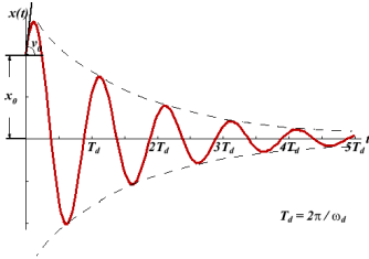
The effect of radiation by an oscillating system and of the friction present in the system is that the amplitude of oscillations gradually diminishes with time. The reduction in amplitude (or energy) of an oscillator is called damping and the oscillation are said to be damped.
When the energy of a oscillating system is gradually dissipated by friction and other resistances, the oscillations are said to be damped. Theoscillations gradually reduce or change in frequency or intensity or cease and the system rests in its equilibrium position.
Damped oscillations refer to oscillations where the oscillating object loses its energy to the surroundings.
Damping, in physics, restraining of vibratory motion, such as mechanical oscillations, noise, and alternating electric currents, by dissipation of energy. Unless a child keeps pumping a swing, its motion dies down because of damping. Shock absorbers in automobiles and carpet pads are examples of damping devices.
A system may be so damped that it cannot oscillate. Critical damping just prevents oscillation or is just sufficient to allow the object to return to its rest position in the shortest period of time.
|
Figure 10: Damped Oscillations
There are many types of mechanical damping. Friction, also called in this context dry, or Coulomb, damping, arises chiefly from the electrostatic forces of attraction between the sliding surfaces and converts mechanical energy of motion, or kinetic energy, into heat.The motion of aoscillating body is also checked by its friction with the gas or liquid through which it moves.
DAMPED HARMONIC OSCILLATOR – HEAVY, CRITICAL AND LIGHT DAMPING
Damped Oscillations
In real systems, there is always a resistance or friction, which leads to a gradual damping of the oscillations. In many cases, the resistance force (denoted by FC) is proportional to the velocity of the body, that is
FC=−cx′.
Then, taking into account the force of resistance, the differential equation for the “mass-spring” system is written as
mx′′+cx′+kx=0, ⇒ x′′+  x′+
x′+ x=0
x=0
We introduce the following notations:  =2β,
=2β,  =
=  . Here ω0 is the natural frequency of the undamped oscillator (previously, we denoted it as ω), β is the damping coefficient. In the new notations, the differential equation looks like
x′′+2βx′+ x=0.
x=0.
We will seek the solution of this equation as a function
x(t)=Aeλt.
The derivatives are given by
x′(t)=Aλeλt, x′′(t)=Aλ2eλt.
Substituting this into the differential equation, we obtain the algebraic characteristic equation:
Aλ2eλt+2βAλeλt+ Aeλt=0,
⇒λ2+2βλ+ =0.
=0.
The roots of this equation are
D=4β2−4 ,
,
|
It can be seen that depending on the sign of the radicand β2− , there may be three different types of solutions.
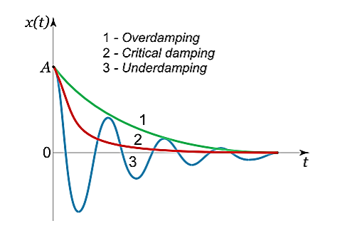
Case 1. Overdamping or Heavy Damping: β>ω0
When resistance to motion is.very strong, the system is said to be heavily damped. Can you name a heavily damped system of practical interest? Springs joining wagons of a train constitute the most important heavily damped system. In your physics laboratory, vibrations of a pendulum in a viscous medium such as thick oil and motion of the coil of a dead beat galvanometer are heavily damped systems.
In this case (the case of strong damping), the radicand is positive: β2> . The roots of the characteristic equation are real and negative. The general solution of the differential equation has the form
x(t)=C1eλ1t+C2eλ2t,
where the coefficients C1, C2, as usual, depend on the initial conditions.
It follows from this expression that there are no oscillations and the system returns to equilibrium exponentially, i.e. a periodically (Figure 11).
|
Figure 11: Heavy, Critical And Light Damping
Case 2. Critical Damping: β=ω0
You may have observed that on hitting an isolated road bump, a car bounces up and down and the occupants feel uncomfortable. To minimise this discomfort, the bouncing caused by the road bumps must be damped very rapidly and the automobile is restored to equilibrium quickly. For this we use critically damped shock absorbers. Critical damping is also useful in recording instruments such as a galvanometer (pointer type as well as suspended coil type) which experience sudden impulses. We require the pointer to move to the correct position in minimum time and stay there without executing oscillations. Similarly, a ballistic galvanometer coil is required to return to zero displacement immediately.
In the limiting case when β=ω0, the roots of the characteristic equation are real and coincide:
λ1=λ2=−β=−ω0.
Here the solution is given by the formula
x(t)=(C1t+C2)
In this mode, the value of x(t) may even increase at the beginning of the process because of the linear factor C1t+C2. But in the end the deflection x(t) decreases rapidly due to the exponential decay with a characteristic time τ=2π/ω0.
Note that in this critical mode the relaxation occurs faster than in the case of the aperiodic damping (Case 1). Indeed, in this mode the relaxation time will be determined by the smaller (in absolute value) root λ1, and will be given by the formula
|
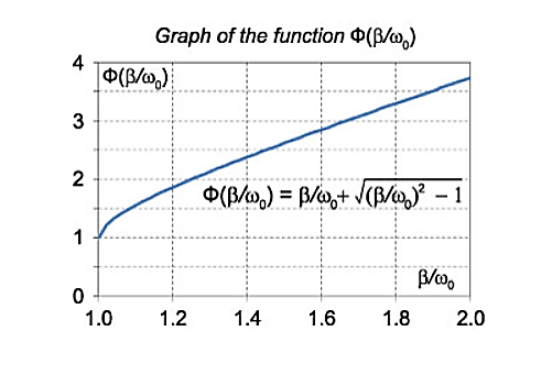
The function Φ(β/ω0) included in this expression is monotonically increasing. It is always greater than or equal to 1, as shown in Figure 12

|
Figure 12:Graph
In the critical case (Case 2) the ratio βω0 is 1, and βω0>1 in the case of the aperiodic damping (Case 1). Therefore for the aperiodic damping mode, we can write
τ= Φ(
Φ( ) >
) >
Thus, the critical damping mode provides the fastest possible return of the system to equilibrium. This is often used, for example, in door closing mechanisms.
Case 3. Underdamping or Light Damping β<ω0
Here the roots of the characteristic equation are complex conjugate:
λ1,2 =−β±i√
The general solution of the differential equation is oscillatory in nature and can be written as
x(t)=e−βt[C1cos(ω1t)+C2sin(ω1t)]
where the oscillation frequency ω1 is equal to
ω1=
The resulting formula can be written in a somewhat different form:
x(t)=Ae−βtcos(ω1t+φ0),
where φ0 is the initial phase of the oscillations and Acosφ0 is the initial amplitude of the oscillations. We see that classical damped oscillations occur in this mode. Here the oscillation frequency ω1 is less than the harmonic frequency ω0, and the oscillation amplitude decreases exponentially with e−βt.
Key Takeaways
- Damped oscillations refer to oscillations where the oscillating object loses its energy to the surroundings.
- When resistance to motion is.very strong, the system is said to be heavily damped.β>ω0
- The critical damping mode provides the fastest possible return of the system to equilibrium..β= ω0
- In Case of Underdamping or Light Dampingclassical damped oscillations occurβ<ω0
The energy loss rate of a weakly damped (i.e.,ν ) harmonic oscillator is conveniently characterized in terms of a parameter, Qf, which is known as the quality factor. This quantity is defined to be 2π times the energy stored in the oscillator, divided by the energy lost in a single oscillation period. If the oscillator is weakly damped then the energy lost per period is relatively small, and Qf is therefore much larger than unity. Roughly speaking, Qfis the number of oscillations that the oscillator typically completes, after being set in motion, before its amplitude decays to a negligible value. Let us find an expression forQf.
As we have seen, the motion of a weakly damped harmonic oscillator is specified by
 (1)
(1)
It follows that
| (2) |
the energy lost during a single oscillation period is


|
(3)
In the weakly damped limit, ν , the exponential factor is approximately unity in the interval t=ϕ/ω1to (2π+ϕ)/ω1 , so that
|
(4)
Whereθ =ω1t-ϕ. Thus,
|
(5)
because, as is readily demonstrated,
Hence, we obtain
|
Yet another way of expressing the damping effect is by means of the rate of decay of energy.
we note that the average energy of a weakly damped oscillator decays to Eoe-1 in time t = =
=  seconds. If ωd is its angular frequency, then in this time the oscillator will vibrate through ωd m/
  radians. The number of radians through which a weakly damped system oscillates as its average energy decays to Eoe-1 isa measure of the quality factor Q.
You will note that Q is only a number and has no dimensions. In general, is small so that Q is very large. A tuning fork has Q of a thousand or so, whereas a rubber band exhibits a much lower (-10) Q. This is due to the internal friction generated by the coiling of the long chain of molecules in a rubber band. An undamped oscillator ' (
 = 0) has an infinite quality factor.
For a weakly damped mechanical oscillator, the quality factor can be expressed in term; of the spring factor and damping constant. For weak damping,
ωd ωd-
ωd- 
Q = 
That is, the quality factor of a weakly damped oscillator is directly proportional to the square root of k and inversely proportional to .
.
In a more physically meaningful form
Q = =
|
Key Takeaways
- The energy loss rate of a weakly damped (i.e.,ν
 ) harmonic oscillator is conveniently characterized in terms of a parameter, Qf, which is known as the quality factor
 - Qfis the number of oscillations that the oscillator typically completes, after being set in motion, before its amplitude decays to a negligible value.
- It is given by Q =

FORCED OSCILLATION
The oscillation of a oscillator is said to be forced oscillator or driven oscillation if the oscillator is subjected to external periodic force.
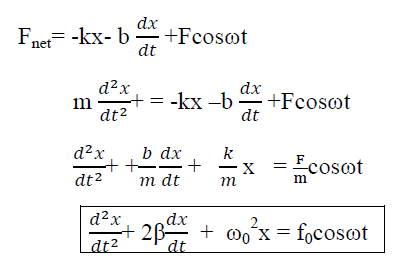
If an external periodic sinusoidal force Fcosωt acts on a damped oscillator, its equation of motion is written as,
|
…………(1)
Where β= b/2m,  = k/m and f0 = F/m , and β and
  respectively called as damping coefficient, natural frequency.
Equation (1) is also represented as
 = f0cosωt
Equation (1) represents the general equation of forced oscillation.
Equation (1) is a non-homogenous differential equation with constant co-efficient. For weak damping ( >β 2) , the general equation contains,
x(t) = xc(t) + xp(t)
Where xc(t) is called complementary solution and its value is
|
…………(2)
Now xp(t) is called the particular integral part.
Let us choose
xp(t) = P cos (ωt-δ)
 (t)= -Pωsin(ωt-δ)
 (t)=-Pω2cos(ωt-δ) ……………(3)
Putting xp(t) , (t),
(t), (t)in equation (1) we get
|
|
Now, comparing the coefficient of cos(ωt-δ) and sin (ωt-δ) on both sides,
( -ω2)P = f0cosδ ……………(4)
2βPω = f0sinδ ……………(5)
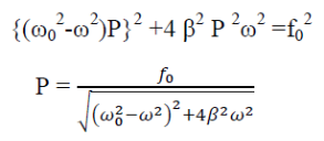
Squaring and adding eqn (4) & (5)
Now dividing equation (5) by (6)
This is steady state solution. Now x(t) = xc(t) + xp(t)
|
|
STEADY STATE BEHAVIOUR
Frequency:-The Oscillator oscillates with the same frequency as that of the periodic force.
ω0and ω are very close to each other then beats will be produced and these beats are transient as it lasts as long as the steady state lasts. The duration between transient beats is determined by the damping coefficient β.
PHASE: The phase difference δ between the oscillator and the driving force or between the displacement and driving is
|
This shows that there is a delay between the action of the driving force and response of the oscillator.
Figure 13: Driving force and response of the oscillator.
(In the above figure fQ= ω0 and fp= ω)
At ω=ω0, φ =π/2, the displacement of the oscillator lags behind the driving force byπ/2.
At ω<<ω0 then δ=0→δ=0
For ω>>ω0 then δ =-2p/ω→ -0=π
AMPLITUDE: The amplitude of driven oscillator, in the steady state, is given by
|
It depends upon ( -ω2). If it is very small, then the amplitude of forced oscillation increases.
Case-1:At very high driving force i.eω>>ω0 and damping is small (β is small) or (β→0)
A = 
A =  =
= 
Amplitude is inversely proportional to the mass of the oscillator & hence the motion is mass controlled motion.
Case-2:At very low driving force (ω<<ω0) and damping is small (β→0),
i.e.  -ω2 =
-ω2 = 
A = 
A =  =
= 
So, when the low driving force is applied to oscillator, the amplitude remains almost constant for low damping. The amplitude of the forced oscillator in the region ω<<ω0and β<ω0 is inversely proportional to the stiffness constant (k) and hence motion is called the stiffness controlled motion.
Case:-3 (Resistance controlled motion)
When angular frequency of driving force=natural frequency of oscillator i.e.(ω=ω0)
A =  =
= 
A=f/bω=f/bω0
RESONANCE
Resonance occurs when:-
Frequency of the external periodic force = Natural frequency of the system.
Definition:-The phenomena of producing oscillatory motion in a system by the influence of an external periodic force having the same frequency as that of natural frequency of the system is called Resonance.
Example:- Resonance causes disaster during earthquake. When the natural frequency of the building becomes equal to the frequency of the periodic vibration present in the earth during earthquake, then the building starts vibrating with large amplitude and hence it collapses.
Sit in front of a piano sometime and sing a loud brief note at it with the dampers off its strings. It will sing the same note back at you—the strings, having the same frequencies as your voice, are resonating in response to the forces from the sound waves that you sent to them. Your voice and a piano’s strings is a good example of the fact that objects—in this case, piano strings—can be forced to oscillate but oscillate best at their natural frequency. In this section, we shall briefly explore applying a periodic driving force acting on a simple harmonic oscillator. The driving force puts energy into the system at a certain frequency, not necessarily the same as the natural frequency of the system. The natural frequency is the frequency at which a system would oscillate if there were no driving and no damping force.
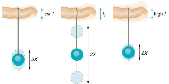
Most of us have played with toys involving an object supported on an elastic band, something like the paddle ball suspended from a finger in Figure 14 Imagine the finger in the figure is your finger. At first you hold your finger steady, and the ball bounces up and down with a small amount of damping. If you move your finger up and down slowly, the ball will follow along without bouncing much on its own. As you increase the frequency at which you move your finger up and down, the ball will respond by oscillating with increasing amplitude. When you drive the ball at its natural frequency, the ball’s oscillations increase in amplitude with each oscillation for as long as you drive it.
The phenomenon of driving a system with a frequency equal to its natural frequency is called resonance. A system being driven at its natural frequency is said to resonate. As the driving frequency gets progressively higher than the resonant or natural frequency, the amplitude of the oscillations becomes smaller, until the oscillations nearly disappear and your finger simply moves up and down with little effect on the ball.
|
Figure 14: The paddle ball on its rubber band moves in response to the finger supporting it. If the finger moves with the natural frequency f0 of the ball on the rubber band, then a resonance is achieved, and the amplitude of the ball’s oscillations increases dramatically. At higher and lower drivingfrequencies, energy is transferred to the ball less efficiently, and it responds with lower-amplitude oscillations.
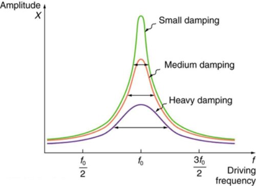
Figure 15 shows a graph of the amplitude of a damped harmonic oscillator as a function of the frequency of the periodic force driving it. There are three curves on the graph, each representing a different amount of damping. All three curves peak at the point where the frequency of the driving force equals the natural frequency of the harmonic oscillator. The highest peak, or greatest response, is for the least amount of damping, because less energy is removed by the damping force.
|
Figure15: Amplitude of a harmonic oscillator as a function of the frequency of the driving force. The curves represent the same oscillator with the same natural frequency but with different amounts of damping. Resonance occurs when the driving frequency equals the natural frequency, and the greatest response is for the least amount of damping. The narrowest response is also for the least damping.
It is interesting that the widths of the resonance curves shown in Figure 15 depend on damping: the less the damping, the narrower the resonance. The message is that if you want a driven oscillator to resonate at a very specific frequency, you need as little damping as possible. Little damping is the case for piano strings and many other musical instruments. Conversely, if you want small-amplitude oscillations, such as in a car’s suspension system, then you want heavy damping. Heavy damping reduces the amplitude, but the trade-off is that the system responds at more frequencies.
Key Takeaways
- The oscillation of a oscillator is said to be forced oscillator or driven oscillation if the oscillator is subjected to external periodic force.
- The Oscillator oscillates with the same frequency as that of the periodic force. ω0 and ω are very close to each other, then beats will be produced.
- The phenomena of producing oscillatory motion in a system by the influence of an external periodic force having the same frequency as that of natural frequency of the system is called Resonance.
- The widths of the resonance curves depend on damping: the less the damping, the narrower the resonance.
Shock Waves
Shock waves areproduced by supersonic aircraft, explosions or lightning. It can also be produced by any other phenomena that create violent changes in pressure. Shock waves are strong pressure waves in any elastic medium like water, solid or air.
When the speed of a moving object in a medium becomes equal to the velocity of sound in the medium the wavefronts cannot escape from the source and pile up. This results in a large amplitude sound barrier.
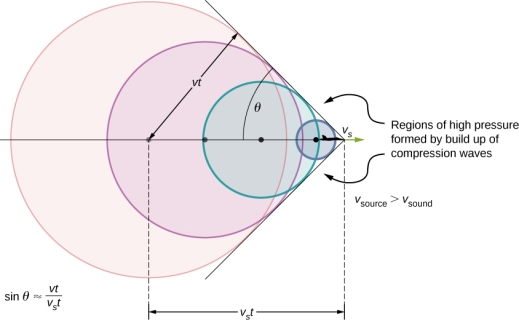
When the speed of the moving object or source exceeds the speed of sound in the medium then the wave fronts lag behind the source forming a cone-shaped region with the source at a vertex. The edge of the cone forms a supersonic wave front with unusually large amplitude called a”shock wave”.
Any sudden release of energy (within fews) will invariably result in the formation of shock waves.It is one of the efficient mechanisms of energy dissipationobserved in nature. The dissipation of mechanical, nuclear, chemical, and electrical energy in a limited space will usually result inthe formation of a shock wave. Because of the dissipative natureof shock waves they invariably need a medium both for generation as well as for propagation.
If the source exceeds the speed of sound, no sound is received by the observer until the source has passed, so that the sounds from the approaching source are mixed with those from it when receding. This mixing appears messy, but something interesting happens—a shock wave is created
Sound waves from a source spread spherically faster as it moves faster than the speed of sound. Sound waves spread from the point where they are emitted.The faster the speed of the source, the smaller the angle θ.
|
Figure16: Shock Wave
Constructive interference along the lines shown (a cone in three dimensions) from similar sound waves arriving there simultaneously. This superposition forms a disturbance called a shock wave, a constructive interference of sound created by an object moving faster than sound. Inside the cone, the interference is mostly destructive, so the sound intensity there is much less than on the shock wave.
Shock waves are different from sound waves. In sound wave compression takes place in waves but in case of Shock waves, there exists a region in which sudden and violent change in stress, density and temperature take place. This is the reason shock waves propagate in different manner from that of ordinary acoustic waves.
Shock waves travel faster than sound waves also their speed increases as the amplitude is increased whereas the intensity of a shock wave decreases faster than that of a sound wave. The reason behind this is some of the energy of the shock wave is used up to heat the medium in which it travels.
The amplitude of a strong shock wave, as created in air by an explosion, decreases almost as the inverse square of the distance until the wave has become so weak that it obeys the laws of acoustic waves.
If the speed of the shock wave equals the normal speed then the shock wave dies and is reduced to anordinary sound wave.
Shock waves alter the mechanical, electrical, and thermal properties of solids and, thus, can be used to study the equation of stateof any material.
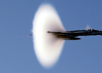
A sonic boom is the intense sound that occurs as the shock wave moves along the ground. Shock waves generated when a fighter jet attains the speed of sound is as shown in the figure.
|
Figure17: Shock Wave by fighter jet
Key Takeaways
- When the speed of the moving object or source exceeds the speed of sound in the medium then the wave fronts lag behind the source forming a cone-shaped region with the source at a vertex. The edge of the cone forms a supersonic wave front with unusually large amplitude called a”shock wave”.
- It can also be produced by any other phenomena that create violent changes in pressure.
- Sound waves from a source spread spherically faster as it moves faster than the speed of sound.
- The amplitude of a strong shock wave, as created in air by an explosion, decreases almost as the inverse square of the distance
The Mach numberis named after the name of scientist Ernst Mach. It is defined as the ratio of speed of the object to the speed of the sound in the surrounding medium.
Consider an object moving in a fluid. Let vo be the velocity of the object in the medium. The velocity of soundin the medium is vs.
Mathematically Mach number M is given by
M = ………………(1)
It is a dimensionless quantity.
Mach 0.5 represents half the speed of sound and Mach 2 represents twice the speed of sound.
Subsonic: Speeds of waves less than the speed of sound have a Mach number between zero and one and are described as subsonic.
Supersonic: Speeds of waves greater than the speed of sound have Mach numbers greater than one are a described as supersonic.
Transonic: Speeds approximately equal to the speed of sound have Mach numbers approximately equal to one and are described as transonic.
We can use Mach number in following the cases
1. When an object is moving in a fluid.
2. When the fluid is moving around an object.
The shock wave from a supersonic object is a cone composed of
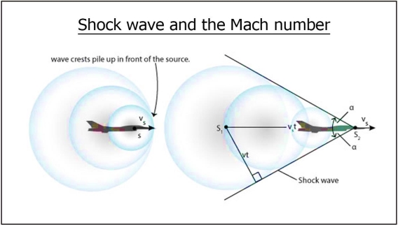
For supersonic object the shock waves form a cone. This cone is composed of overlapping spherical wavefronts.
Let us suppose oneof the wavefronts formpropagates radially outward at speed vo and thus acquires a radius vot. At the same timethe source is traveling at speed vs moves forward vst.
The two displacements form the base and hypotenuse of thetriangle used to determine Mach angle at the vertex of the shock cone.
sinθ = …………….(2)
If the object is Traveling at the speed of sound then the Mach number is equal one and results in a Mach angleof ninety degrees.
|
Figure18: Shock Wave and Mach Number
If the speed of the object is transonic speeds then the shock wave is a wall of high pressuremoving along with the object in a direction perpendicular to its velocity.
For supersonic speed Mach number isless than one and the Mach angle is less than ninety degrees. The faster the object moves, the narrower the coneof high pressure behind it becomes.
Measuring the vertex angle is thus a simple way to determine the speed of asupersonic object.
Let us simplify the above concept by considering an example of aircraft. If an aircraft flying faster than the speed of sound (about 1,230 kilometres per hour, or 764 miles per hour), the shock wave takes the form of a cone in three-dimensional space called the Mach cone. The Mach number is defined as the ratio of the speed of the aircraft to the speed of sound. The higher the Mach number—that is, the faster the aircraft—the smaller the angle of the Mach cone.
Key Takeaways
- The Mach number is defined as the ratio of speed of the object to the speed of the sound in the surrounding medium.
- Mathematically Mach number M is given by
M = 
- It is a dimensionless quantity.
- Subsonic: Speeds of waves less than the speed of sound have a Mach number between zero and one and are described as subsonic.
- Supersonic: Speeds of waves greater than the speed of sound have Mach numbers greater than one are a described as supersonic.
- Transonic: Speeds approximately equal to the speed of sound have Mach numbers approximately equal to one and are described as transonic.
Properties of Shock waves
- Shock waves are essentially non-linear waves that propagate at supersonic speeds. Such disturbances occur in steady transonic or supersonic flows, during explosions, earthquakes, hydraulic jumps and lightning strokes.
- Shock waves are characterized as strong or weak depending upon the instantaneous changes in the properties like pressure and temperature that they bring about in the medium of propagation.
- Shock waves travel faster than sound waves also their speed increases as the amplitude is increased
- Shock waves alter the mechanical, electrical, and thermal properties of solids and, thus, can be used to study the equation of state of any material.
- The intensity of a shock wave decreases faster than that of a sound wave.
- Shock waves need a medium both for generation as well as for propagation.
- A shock wave carries energy and can propagate through a medium like any other ordinary wave.
- A shock wave is characterized by a sudden discontinuity in change of pressure, temperature and density of the medium.
- The energy and speed of a shock wave dissipates with respect to the distance.
- Energy of the shock wave is conserved when it passes through matter but its entropy increases.
Control volume,
A control volume is defined straddling the shock.
Control volume is the mathematical idea used for creating a mathematical model for a physical process.
We know that for an inertial frame of reference either volume is fixed in space or moving with constant velocity through which the fluid flows.
A shock wave is characterized by a sudden discontinuity. We know that energy of the shock wave is conserved when it passes through matter but its entropy increases. Since no fluid flow shows discontinuity thus a control volume is established around the shock wave, with the control surfaces that bound this volume parallel to the shock wave.
Control surface is in such a way that one surface lie on the pre-shock side of the fluid medium and one on the post-shock side. The two surfaces are separated by a very small depth such that the shock itself is entirely contained between them.
The surface enclosing the control volume is referred to as the control surface. At such control surfaces, momentum, mass flux and energy are constant.
The basic law of conservation is mass can neither be created nor destroyed. For a closed system the total mass of the system remains constant. Mathematically
msys = Constant
Hence
 = 0
= 0
For a control volume or open system conservation of mass is expressed in the rate form as
 -
- =
= 
Where
 = the mass flow into the control volume
 = the mass flow out of the control volume
 = is the rate of change of mass within the control volume boundaries.
The equation (2) is known as continuity equation in fluid mechanics.
Laws of conservation of mass, energy and momentum
We know that properties of the shock wave in these two regions are sharply distinguishable because shock wave shows discontinuous behaviour; these are not like normal continuous sound waves.
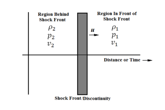
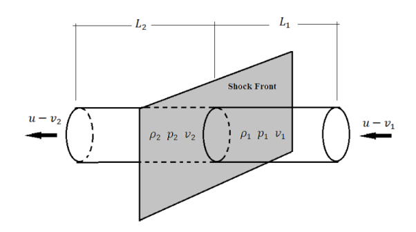
The transition between the region in front of the shock front and the region behind the shock front is not smooth. For the sake of clarity, subscript 1 refers to conditions ahead of the shock front and subscript 2 refers to conditions behind (or after) the shock front as shown in Figure.
|
Figure 19: The one-dimensional shock front creates a discontinuity
Here
u is the speed of the shock front.
ρ is the mass density of the fluid
p is the mass density of the fluid
v is the velocity of the fluid
Here we will consider the system where the fluid is initially at rest and we will limit the problem to one dimension.
A shock wave carries energy through a medium. However, entropy is not constant. The system is not isentropic.
Energy is dissipated in such forms as heat and sound, and the process is not thermodynamically reversible. Shock waves are not linear. Pressure, mass density, and velocity propagate in space and time as follows
p(x,t) = p(x-ut)
ρ(x,t) = ρ(x-ut)
v(x,t) = v(x-ut) ………………….(1)
The velocity of the shock is treated as a constant even in real applications where the medium through which the shock front is propagating has some inhomogeneity.
For the functions in Equation (1), the space and time derivatives are related by
 = -u
= -u 
This can then be utilized for analyzing the conservation equations.
Conservation of Mass
For one dimension system, the conservation of mass becomes
 …………..(2)
The regions before and after the shock front are required to be steady, upon integrating Equation (2) over the shock front, we obtain the following
 …………..(3)
Another possibly way is as follows
Conservation of mass basically means mass entering the system must equal the mass leaving the system, where mass is equal to the density time the volume
m = ρv
If we take a look at our volume of fluid we know that our volume on one side of the shock front is equal to the area A times the length.
|
Figure 20: Our fixed eulerian volume. We can use the relative speeds of particles on either side of the shock front to analyze conservation of mass.
The length Lias shown in the figure is given by the distance a particle travels relative to the shock front. This is simply
L =t x v
here v is u-vi (relative velocity).
So our mass is given by
m =ρiALi
where i is 1 or 2 representing the mass in front of or behind the shock front. We equate the incoming and outgoing masses because the continuity equation and have:
|
…………..(4)
which can be rewritten to match Equation (3) exactly.
Conservation of Momentum
It is given by the total momentum of the system is always conserved.
By applying Newton’s second law ofmotion to the control volume the conservation of momentum is
“Any change in momentum of the fluid within a control volume is due to the net flow of fluid into the volume and the action of external forces on the fluid within the volume.”
Equation for the conservation of momentum
|
…………..(5)
The conservation of momentum comes from the fact that any applied force to our control volume must equate to the rate of change of the momentum as we go from the region before the shock front to the region after the shock front. This applied force is given by the pressure difference across the shock front times the area where the force is applied:
F = (P2 –P1)A
The area A is again the cross-sectional area of our control volume. The time rate of change of the momentum is

Here we can plug in our known value of mass fromthe conservation of mass:
m = ρiAt(u-vi)
and the rate becomes
rate =  …………..(6)
We equate this to our force in Equation () and cancel the area and time terms. This gives us the following result for conservation of momentum:
 …………..(7)
After multiplying everything through the parentheses we obtain the same result as Equation (5), as expected.
Conservation of energy
It deals with energy can neither be created nor destroyed. In other words total energy of a system remains constant.
In case of a fluid system under adiabatic conditions the total energy entering the system must be same as the total energy leaving the system. The total energy of the control volume remains constant.
Equation for the conservation of energygives us the simplified energy equation where the energies given by an equation of state dependent on pressure and density.
|
…………..(8)
Key Takeaways
- Properties of the shock wave in these two regions are sharply distinguishable because shock wave shows discontinuous behaviour.
- Conservation of mass basically means mass entering the system must equal the mass leaving the system, where mass is equal to the density time the volume.
- Mass Conservation Equation is given by
|
- The conservation of momentum comes from the fact that any applied force to our control volume must equate to the rate of change of the momentum as we go from the region before the shock front to the region after the shock front.
- Conservation of momentum equation is given by

- Conservation of Energy deals with energy can neither be created nor destroyed. In other words total energy of a system remains constant. Equation is given by
|
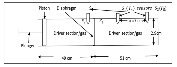
ReddyShocktube is a device used to produce and study shock waves in the laboratory.Reddy tube is the first such devise which is capable of producing shock waves with Mach numbers exceeding 1.5 by simple hand operation.Schematic labeled diagram of the original Reddy shock tube is as shown in the diagram.
|
Figure 21: ReddyShocktube
Construction:
1. Reddy Shock Tube consists of a steel tube of length 100 cm and diameter 2.9 cm.
2. A diaphragm of thickness 0.1cm divides the tube in to two compartments of length 49 cm fitted with piston called Driver section filled with driver gas. The other compartment of length 51 cm is called Driven section filled with driven gas.
3. Sensor S fitted to driver section measures the rupture pressure P2, temperature T2.
4. Two sensors S1 and S2 separated by a distance ∆xfitted to driven section measures the pressures P4 and P5and temperatures T4, T5 respectively.
Working:
1. Driver section is filled with gas at high pressure and Driven section is filled with gas of low pressure P1 and temperature T1.
2.Diaphram is ruptured to produce shock waves by pushing the piston and the rupture pressure P2& temperature is measured using sensor S.
3.The time ‘t′ taken by the shock wave to travel the distance ‘x’ is measured using CRO. also the pressures P4,P5 and temperatures T4,T5 are measured using the sensors S1 and S2 respectively.
4.The speed of the shock waves is calculated using V =x/𝑡.
5.Then the match number of the shock waves is calculated using M = v/a ,where a is the speed of sound at temperature T1.
6. Also the mach number M can be calculated using the RH relations
|
by finding P2 andP1 for the gas of known  .
.
Key Takeaways
- Reddy tube is the first such devise which is capable of producing shock waves with Mach numbers exceeding 1.5 by simple hand operation.
- Reddy Shock Tube consists of a steel tube. Driver section is filled with gas at high pressure
- The speed of the shock waves is calculated using V =x/𝑡.
- The Mach number M can be calculated using the RH relations
|
Applications of shock waves
The ability of shock waves to instantaneously increase the pressureand temperature in a medium of propagation enables theiruse for many novel industrial applications. Thereis no other method by which you can achieve high pressure andtemperature in a medium so quickly.
- Shock waves can also be used to push preservative solutions into wood samples like bamboo where conventional methods do not work.
- Mach reflection of a shock wave is used to remove micron size dust particles from the surface of silicon wafers.
- Shock waves are used in medical therapy in orthopaedics and for breaking kidney stones.
- Shock waves are used in pencil industries to impregnate preservatives into wood slats.
- Shock waves are used in sandal oil extraction.
- Shock waves are used in cell transformation.
- Shock waves are used in geophysics.
In the coming years shock wave dynamics will emerge asa strong area of interdisciplinary research and we may see manycommercial devices working based on shock wave phenomena
1 Question: Which of the following represent simple harmonic motion?
(i) x = A sin ωt + B cos ωt
(ii) x = A sin ωt+ B cos 2ωt
(iii) x = A eiωt
(iv) x = A ln ωt
Solution:
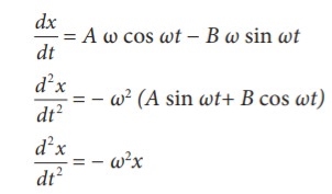
(i) x = A sin ωt + B cos ωt
|
This differential equation is similar to the differential equation of SHM Therefore, x = A sin ωt + B cos ωt represents SHM.
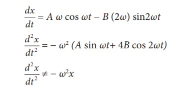
(ii) x =A sin ωt + B cos2ωt
|
This differential equation is not like the differential equation of a SHM Therefore, x = A sin ωt + B cos 2ωt does not represent SHM.
(iii) x =Aeiωt
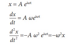
This differential equation is like the differential equation of SHM. Therefore, x = A eiωt represents SHM.
(iv) x = A ln ωt
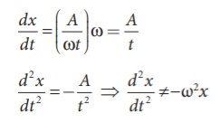
This differential equation is not like the differential equation of a SHM Therefore, x = A ln ωt does not represent SHM.
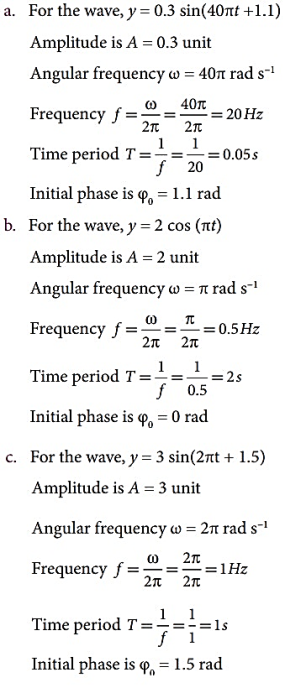
2 Question:Calculate the amplitude, angular frequency, frequency, time period and initial phase for the simple harmonic oscillation given below
a. y = 0.3 sin (40πt + 1.1)
b. y = 2 cos (πt)
c. y = 3 sin (2πt − 1.5)
Solution
Simple harmonic oscillation equation is y = A sin(ωt + φ0) or y =A cos(ωt + φ0)
|
3 Question:Show that for a simple harmonic motion, the phase difference between
a. displacement and velocity is π/2 radian or 90°.
b. velocity and acceleration is π/2 radian or 90°.
c. displacement and acceleration is π radian or 180°.
Solution:
a. The displacement of the particle executing simple harmonic motion
y = A sinωt
Velocity of the particle is
v = Aωcosωt = Aωsin(ωt+ π /2)
The phase difference between displacement and velocity is π/2.
b. The velocity of the particle is
v = A ω cos ωt
Acceleration of the particle is
a = Aω2sinωt = Aω2cos(ωt+ π /2)
The phase difference between velocity and acceleration is π/2.
c. The displacement of the particle is y = A sinωt
Acceleration of the particle is
a = − A ω2 sin ωt = A ω2 sin(ωt + π)
The phase difference between displacement and acceleration is π.
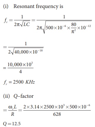
4 Question:A 500 μH inductor, 80/π2 pF capacitor and a 628 Ω resistor are connected to form a series RLC circuit. Calculate the resonant frequency and Q-factor of this circuit at resonance.
Solution
L=500×10-6H; C = 80/π2 ×10−12 F; R = 628Ω
|
5 Question: In an LC circuit, the self-inductance is 2.0  10-2H and the capacitance is 8.0
  10-6F. At t=0, all of the energy is stored in the capacitor, which has charge 1.2
 10-5F.
(a) What is the angular frequency of the oscillations in the circuit?
(b) What is the maximum current flowing through circuit?
(c) How long does it take the capacitor to become completely discharged?
(d) Find an equation that representsq(t).
Solution:
- the angular frequency of the oscillations is
ω= =
=  = 2.5 x 10³ rad/s
b. The current is at its maximum I0 when all the energy is stored in the inductor. From the law of energy conservation,
 ×LI02
×LI02  ×
×
I0 =  q0 =2.5 x 103 x 1.2
 10-5 = 3.0 x 10⁻² A
This result can also be found by an analogy to simple harmonic motion, where current and charge are the velocity and position of an oscillator.
c. The capacitor becomes completely discharged in one-fourth of a cycle, or during a time T/4 where is the period of the oscillations. Since
T=  =
=  =
=  s
s
the time taken for the capacitor to become fully discharged is
 /4 =
/4 =  s
s
d. The capacitor is completely charged at t=0, So q(0)=q0
q(0)=q0 = q0 cos ϕ
Thus,ϕ=0 , and
q(t)= (1.2 10-5C)cos
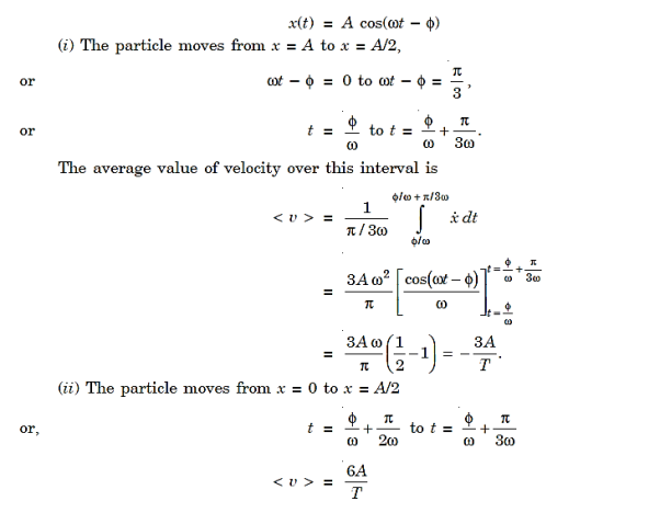
6 Question: A point performs harmonic oscillations along a straight line with a period T = 0.8 s and an amplitude A = 8 cm. Find the mean velocity of the point averaged over the time interval during which it travels a distance A/2, starting from (i) the extreme position, (ii) the equilibrium position.
Solution
We have
|
The magnitude of the average velocity is
|
Reference
- The Physics of Wave and Oscillation by NK Bajaj Tata Mcgraw Hill Edition
- Shock Waves made simple – Chintoo S Kumar, K Takayama and KPJ Reddy: Willey India Pvt. Ltd. New Delhi 2014






![$\displaystyle = m \nu a^{2}\int_{\phi/\omega_1}^{(2\pi+\phi)/\omega_1}{\rm e}...
...{2} \cos(\omega_1 t-\phi) + \omega_1 \sin(\omega_1 t-\phi)\right]^{ 2} dt.$](https://glossaread-contain.s3.ap-south-1.amazonaws.com/epub/1642890915_8061113.png)


