Unit - 1
Manufacturing Methods
Q1) What do you understand by manufacturing process? Classify various manufacturing processes.
A1) Manufacturing Process
Manufacturing process is that part of the production process which is directly concerned with the change of form or dimensions of the part being produced. It does not include the transportation, handling or storage of parts, as they are not directly concerned with the changes into the form or dimensions of the part produced.
Classification of Manufacturing Processes
All processes used in manufacturing concern for changing the ingots into usable products may be classified into six major groups as primary shaping processes, secondary machining processes, metal forming processes, joining processes, surface finishing processes and processes effecting change in properties. These are discussed as under.
Primary Shaping Processes
Primary shaping processes are manufacturing of a product from an amorphous material. Some processes produce finish products or articles into its usual form whereas others do not, and require further working to finish component to the desired shape and size. Castings need re-melting of scrap and defective ingots in cupola or in some other melting furnace and then pouring of the molten metal into sand or metallic moulds to obtain the castings. Thus the
intricate shapes can be manufactured. Typical examples of the products that are produced by casting process are machine beds, automobile engines, carburetors, flywheels etc. The parts produced through these processes may or may not require to undergo further operations.
Some of the important primary shaping processes is:
(1) Casting, (2) Powder metallurgy, (3) Plastic technology, (4) Gas cutting, (5) Bending and (6) Forging.
Secondary or Machining Processes
The secondary processes require the use of one or more machine tools, various single or multi-point cutting tools (cutters), job holding devices, marking and measuring instruments, testing devices and gauges etc. for getting desired dimensional control and required degree of surface finish on the work pieces. The example of parts produced by machining processes includes hand tools machine tools instruments, automobile parts, nuts, bolts and gears etc.
Some of the common secondary or machining processes are—
(1) Turning, (2) Threading, (3) Knurling, (4) Milling, (5) Drilling, (6) Boring, (7) Planning, (8) Shaping, (9) Slotting, (10) Sawing, (11) Broaching, (12) Hobbing, (13) Grinding, (14) Gear cutting, (15) Thread cutting and (16) Unconventional machining processes namely machining with Numerical Control (NC) machines tools or Computer Numerical Control (CNC) machines tools using ECM, LBM, AJM, USM setups etc.
Q2) What do you mean by Casting? Explain its Main Function.
A2) Casting is a manufacturing process in which a solid is dissolved into a liquid, heated to appropriate temperature (sometimes processed to change its chemical formula and is then added into a mold or cavity.
Casting processes are universally used for the manufacture of a wide variety of products. Very small to extremely heavy metal products can be made by casting process.
When it is difficult or economically impossible to produce an item by another process then casting process is best option.
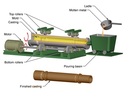
Casting Steps
We should concentrate on the following for successful casting operation:
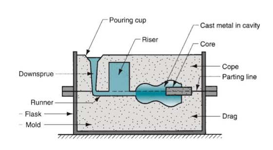
Casting Terminology
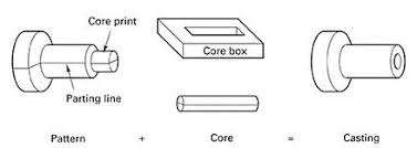
Q3) Explain the functions of Runner and Riser in casting.
A3) Runner is a passage in the mould through which the metal flows through into the main cavity after entering through the downsprue.
Any casting in which shrinkage is significant requires a riser connected to the main cavity. The riser is a reservoir in the mold that serves as a source of liquid metal to compensate for shrinkage of the casting during solidification. The riser must be designed to freeze after the main casting in order to satisfy its function.
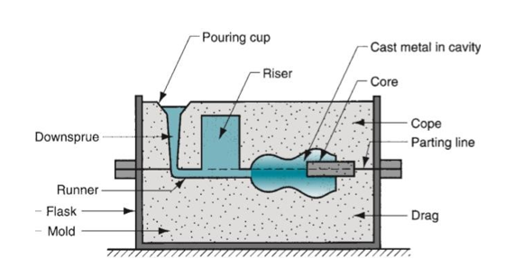
Q4) Explain the function of gating design in casting.
A4) The difficulties faced in pouring and injecting the molten metal in the mould cavity are overcome by using an appropriate gating design. A good gating design ensures distribution of the metal in the mould cavity at a proper rate without excessive temperature loss, turbulence, and entrapping gases and slags. The design of a gating system depends on both the metal and mould compositions.
A compromise has to be made so that the metal enters the mould cavity at optimum velocity avoiding early solidification and erosion of mould surface both.
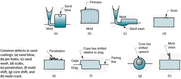
Q5) Explain with neat sketches the various casting defects.
A5) Some defects are common to any and all casting processes. These defects are as follows:
Misruns: These are castings that solidify before completely filling the mold cavity.
Causes of misrun include (i) fluidity of the molten metal is insufficient, (ii) pouring temperature is too low, (iii) pouring is done too slowly, and/or (iv) cross-section of the mold cavity is toothin.
Cold Shuts: These occur when two portions of the metal flow together but there is a lack of fusion between them due to premature freezing. Its causes are similar to those of amisrun.
Cold shots: These result from splattering during pouring, causing the formation of solid globules of metal that become entrapped in the casting. Pouring procedures and gating system designs that avoid splattering can prevent this defect.
Shrinkage cavity: It is a depression in the surface or an internal void in the casting, caused by solidification shrinkage that restricts the amount of molten metal available in the last region to freeze. It often occurs near the top of the casting, in which case it is called a ‘‘pipe.’’ This problem can often be solved by proper riser design.
Micro-porosity: It consists of a network of small voids distributed throughout the casting caused by localized solidification shrinkage of the final molten metal in the dendritic structure. The defect is usually associated with alloys, because of the protracted manner in which freezing occurs in these metals.
Hot tearing or hot cracking: It occurs when the casting is restrained from contraction by an unyielding mold during the final stages of solidification or early stages of cooling after solidification. This defect is because of separation of the metal at a point of high tensile stress caused by the metal’s inability to shrink naturally. In sand casting and other expendable-mold processes, it is prevented by compounding the mold to be collapsible. In permanent-mold processes, hot tearing is reduced by removing the part from the mold immediately after solidification.
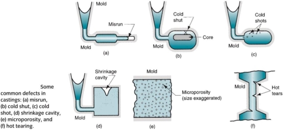
Some defects are related to the use of sand molds, and therefore they occur only in sand castings. Other expendable-mold processes are also susceptible to these problems but to a lesser degree.
Defects found primarily in sand castings are as follows:
Sand blow: It is a defect consisting of a balloon-shaped gas cavity caused by release of mold gases during pouring. It occurs at or below the casting surface near the top of the casting. Low permeability, poor venting, and high moisture content of the sand mold are the usual causes of Sand blow.
Pinholes: These are also caused by release of gases during pouring, consist of many small gas cavities formed at or slightly below the surface of the casting.
Sand wash: It is an irregularity in the surface of the casting that results from erosion of the sand mold during pouring, and the contour of the erosion is formed in the surface of the final cast part.
Scabs: These are rough areas on the surface of the casting due to encrustations of sand and metal. It is caused by portions of the mold surface flaking off during solidification and becoming imbedded in the casting surface.
Penetration: It is a surface defect that occurs when the fluidity of the liquid metal is high, and it penetrates into the sand mold or sand core. Upon freezing, the casting surface consists of a mixture of sand grains and metal. Harder packing of the sand mold helps to alleviate this condition.
Mold shift: It is a defect caused by a sidewise displacement of the mold cope relative to the drag, resulting in a step in the cast product at the parting line.
Core shift: It is similar to mold shift, but it is the core that is displaced, and the displacement is usually vertical. Core shift and mold shift are caused by buoyancy of the molten metal.
Mold crack: It occurs when mold strength is insufficient, and a crack develops, into which liquid metal can seep to form a ‘‘fin’’ on the final casting.
Q6) Give a brief description on Metal Forming Processes
A6) Forming processes encompasses a wide variety of techniques, which make use of suitable force, pressure or stresses, like compression, tension and shear or their combination to cause a permanent deformation of the raw material to impart required shape. These processes are also known as mechanical working processes and are mainly classified into two major categories i.e., hot working processes and cold working processes. In these processes, no material is removed; however it is deformed and displaced using suitable stresses like compression, tension, and shear or combined stresses to cause plastic deformation of the materials to produce required shapes. Such processes lead to production of directly usable articles which include kitchen utensils, rods, wires, rails, cold drink bottle caps, collapsible tubes etc. Some of the important metal forming processes are:
Hot working Processes
(1) Forging, (2) Rolling, (3) Hot spinning, (4) Extrusion, (5) Hot drawing and (6) Hot spinning.
Cold working processes
(1) Cold forging, (2) Cold rolling, (3) Cold heading, (4) Cold drawing, (5) Wire drawing,
(6) Stretch forming, (7) Sheet metal working processes such as piercing, punching, lancing,
notching, coining, squeezing, deep drawing, bending etc.
Forging
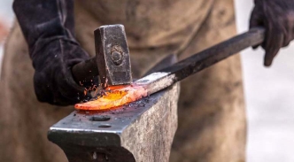
Forging is defined as the plastic deformation of metals at elevated temperatures into a predetermined size or shape using compressive forces exerted through some means of hand hammers, small power hammers, die, press or upsetting machine. It consists essentially of changing or altering the shape and section of metal by hammering at a temperature of about 980°C, at which the metal is entirely plastic and can be easily deformed or shaped under
pressure.
Forging operation can be accomplished by hand or by a machine hammer. Forging processes may be classified into hot forging and cold forgings and each of them possesses their specific characteristics, merits, demerits and applications. Hand forging process is also known as black-smithy work which is commonly employed for production of small articles using hammers on heated jobs.
Q7) List any six forging defects.
A7) Forging defects:
1. Unfilled Section:
As the name implies in this type of defect some of the forging section remain unfilled. This is due to poor design of die or poor forging technic. This is also due to less raw material or poor heating. This defect can be removed by proper die design, proper availability of raw material and proper heating.
2. Cold Shut:
Cold shut includes small cracks at corners. These defects occur due to improper design of forging die. It is also due to sharp corner, and excessive chilling in forge product. The fillet radius of the die should be increase to remove these defects.
3. Scale Pits:
Scale pits are due to improper cleaning of forged surface. This defect generally associated with forging in open environment. It is irregular deputations on the surface of forging. It can be removed by proper cleaning of forged surface.
4. Die Shift:
Die shift is caused by misalignment of upper die and lower die. When both these dies are not properly aligned the forged product does not get proper dimensions. This defect can be removed by proper alignment. It can be done by provide half notch on upper die and half on lower die so at the time of alignment, both these notches will matched.
5. Flakes:
These are internal cracks occur due to improper cooling of forge product. When the forge product cooled quickly, these cracks generally occur which can reduced the strength of forge product. This defect can be removed by proper cooling.
6. Improper Grain Growth:
This defect occurs due to improper flow of metal in casting which changes predefine grain structure of product. It can be removed by proper die design.
Q8) Write the steps of Machining Process? Explain its use.
A8)
Cutting Tool Materials
Q9) Differentiate between machine and machine tool.
A9) Machine is any assembly of links with relative motion between them in order to do useful work whereas machine tool is a machine with the specific purpose of performing machining for which it has arrangements of holding work piece and cutting tool, and arrangements provided for obtaining the necessary relative motion between the two so that desired shape, size and finish can be obtained by removing material from the work piece in form of small chips. Examples of machine tools include lathe machine, milling machine, drilling machine, boring machine, grinding machine, shaper, planer, etc.
Classification of Machining Process
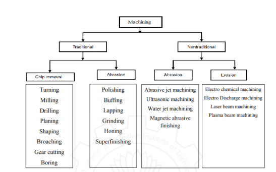
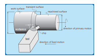
Turning is the most important machining process and can produce a wide variety of parts. Primarily, turning is used to produce parts cylindrical in shape by a single point cutting tool on lathes. The cutting tool is fed either linearly in the direction parallel or perpendicular to the axis of rotation of the workpiece, or along a specified path to produce complex rotational shapes. The primary motion of cutting in turning is the rotation of the workpiece, and the secondary motion of cutting is the feed motion.
Lathes generally are considered to be the oldest member of machine tools, having been first developed in the late eighteenth century. The most common lathe is called an engine lathe because it was one of the first machines driven by Watt’s steam engine. The basic lathe has the following main parts: bed, headstock, tailstock, and carriage. The types of lathes available for a variety of applications may be listed as follows: engine lathes, bench lathes, horizontal turret lathes, vertical lathes, and automatics. A great variety of lathes and attachments are available within each category, also depending on the production rate required.
Q10) Discuss the operations that can be performed on lathe machine.
A10) Turning is the most important machining process and can produce a wide variety of parts on lathe.
The major sub types of turning are:
Milling
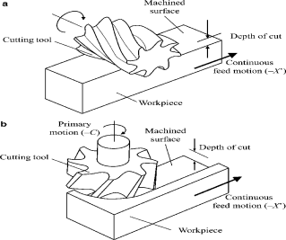
Milling is a process of producing flat and complex shapes with the use of multi-point (or multi-tooth) cutting tool. The axis of rotation of the cutting tool is perpendicular to the direction of feed, either parallel or perpendicular to the machined surface. Milling is usually an interrupted cutting operation since the teeth of the milling cutter enter and exit the workpiece during each revolution.
Drilling
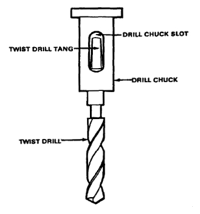
Drilling is a process of producing round holes in a solid material or enlarging existing holes with the use of multi-point cutting tools called drills or drill bits. Various cutting tools are available for drilling, but the most common is the twist drill.
Planning, Shaping and Broaching
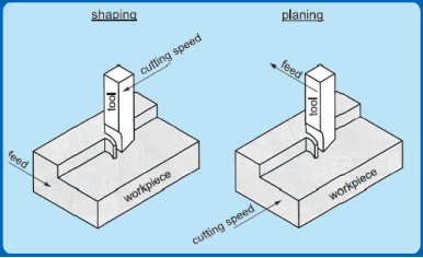
Planning and shaping are similar operations, which differ only in the kinematics of the process. Planning is a machining operation in which the primary cutting motion is performed by the workpiece and feed motion is imparted to the cutting tool. In shaping, the primary motion is performed by the tool, and feed by the workpiece.
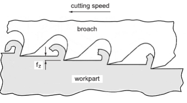
Broaching is a machining operation that involves the linear movement of a multi-point cutting tool (referred to as broach) relative to the workpiece in the direction of the tool axis. The shape of the machined surface is determined by the contour of the final cutting edges on the broach. Broaching is a highly productive method of machining with advantages like good surface finish, close tolerances, and the variety of possible machined surface shapes some of them can only be produced by broaching.
Grinding
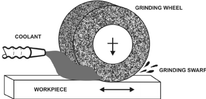
Grinding is the most popular form of abrasive machining. It involves an abrasive tools consisting of grain of hard materials which are forced to rub against the workpiece removing a very small amount of material. Due to the random orientation of grains and some uncontrollable cutting condition, the selection of proper parameters often becomes difficult. Grinding can be performed to produce flat as well as cylindrical (both external and internal) surface efficiently. Grinding is applied when the material is too hard to be machined economically or when tolerances required are very tight.
ABRASIVE PROCESSES
Abrasive processes consist of a variety of operations in which the tool is made of an abrasive material, the most common examples of which are grinding (using wheels, known as bonded abrasives), honing, and lapping. An abrasive is a small, non-metallic hard particle having sharp cutting edges and an irregular shape. Abrasive processes, which can be performed on a wide variety of metallic and non-metallic materials, remove material in the form of tiny chips and produce surface finishes and dimensional accuracies that are generally not obtainable through other machining or manufacturing processes.
Q11) Explain the types of joining operations.
A11) Assembly is the basic type of manufacturing operation in which two or more separate parts are joined to form a new entity. Components of the new entity are connected either permanently or semi-permanently. Permanent joining processes include welding, brazing, soldering, and adhesive bonding. They form a joint between components that cannot be easily disconnected.
Certain mechanical assembly methods are available to fasten two (or more) parts together in a joint that can be conveniently disassembled. They are called temporary joining processes. The use of screws, bolts, and other threaded fasteners are important traditional methods in this category.
Other mechanical assembly techniques, called semi-permanent processes, form a more permanent connection than temporary processes. These include rivets, press fitting, and expansion fits.
Q12) What do you mean by Advanced Machining Processes?
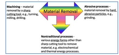
A12) In addition to the mechanical methods of material removal described above, there are a number of other important processes which may be preferred over conventional methods. Among the important factors to be considered are the hardness of the work piece material, the shape of the part, its sensitivity to thermal damage, residual stresses, tolerances, and economics.
Q13) Mention Various types Advanced Machining Methods.
A13) Various Advanced Machining Methods are:
(i) abrasive jet machining (AJM), (ii) ultrasonic machining (USM), (iii) Electrochemical machining (ECM), (iv) Electrochemical grinding (ECG), (v) Chemical machining (CHM), (vi) Electric discharge machining (EDM), (vii) Electron beam machining (EBM), (viii) Laser beam machining (LBM), (ix) Ion beam machining (IBM), (x) Plasma arc machining (PAC).
Abrasive-jet machining (AJM)
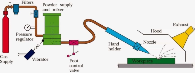
In this material is removed by fine abrasive particles (aluminum oxide or silicon carbide) carried in a high-velocity stream of air, nitrogen, or carbon dioxide. Abrasive Jet Machining (AJM) is used for deburring, etching, and cleaning of hard and brittle metals, alloys, and nonmetallic materials.
Electric-discharge machining (EDM)
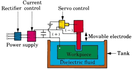
It is based on the principle of erosion of metals by spark discharges. gives a schematic diagram of this process. The spark is a transient electric discharge through the space between two charged electrodes, which are the tool and the workpiece. The discharge occurs when the potential difference between the tool and the workpiece is large enough to cause a breakdown in the medium (which is called the dielectric fluid and is usually a hydrocarbon) and to procure an electrically conductive spark channel. The breakdown potential is usually established by connecting the two electrodes to the terminals of a capacitor charged from a power source.
Some of the major advantages of this process are as follows:
• Complex shapes that are difficult to machine with conventional processes, can be done easily by electro discharge machining process,
• Extremely hard material can be machined to close tolerances,
• Very small work pieces can be handled with sufficient ease, and
• A good surface finish can be obtained.
Ultrasonic machining (USM)
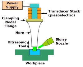
It is a process in which a tool is given a high-frequency, low-amplitude oscillation, which, in turn, transmits a high velocity to fine abrasive particles that are present between the tool and the workpiece. Minute particles of the workpiece are chipped away on each stroke. Aluminium oxide, boron carbide, or silicone carbide grains are used in a water slurry (usually 50 percent by volume), which also carries away the debris.
Chemical machining (CM)
In this material is removed by chemical or electro chemical dissolution of preferentially exposed surfaces of the workpiece. Selective attack on different areas is controlled by masking or by partial immersion. There are two processes involved: chemical milling and chemical blanking
Water jet machining (WJM)
The process is suitable for cutting and deburring of a variety of materials such as polymers, paper, and brick in thicknesses ranging from 0.03 to 1 in (0.8 to 25 mm) or more. The cut can be started at any location, wetting is minimal, and no deformation of the rest of the piece takes place. Abrasives can be added to the water stream to increase material removal rate, and this is known as abrasive water jet machining (AWJM).
Laser beam machining
In laser-beam machining (LBM), material is removed by converting electric energy into a narrow beam of light and focusing it on the workpiece. The high energy density of the beam is capable of melting and vaporizing all materials, and consequently, there is a thin heat affected zone. The most commonly used laser types are CO2 (pulsed or continuous-wave) and Nd: YAG. Typical applications include cutting a variety of metallic and non-metallic materials, drilling (as small as 0.0002 in or 0.005 mm in diameter), and marking.