Unit - 2
CNC Machining, Additive Manufacturing
Q1) What is the significance of CNC Machining?
A1)

Q2) Explain what are the basics of CNC Programming?
A2) There are two ways to program modern CNC machine tools.
1. Conversational Programming. This is the simpler of the two methods. In effect, this is a macro programming language used to instruct the machine to perform pre-programmed cycles (i.e., facing, drilling holes in arrays, etc.). When writing a conversational program, you simply enter the appropriate parameters associated with each machining cycle. This is analogous to using the polar array function in SolidWorks or Pro/E; you don’t have to do the layout or trig to find the location of the features; you just specify the essential parameters and the software does the rest for you.
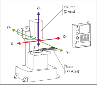
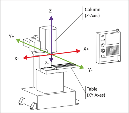
The following cycles are typical of the machining operations available when programming a 3-axis CNC milling machine.
Position. Used to move the XYZ coordinates at rapid federate.
Drill one. Used to position the tool at a specific XYZ coordinate position in order to automatically drill a hole. The automatic drill cycles allow for simple drilling, peck drilling, spot-facing and bore cycles.
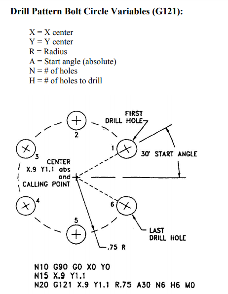
Drill pattern. Used to define polar or rectangular hole arrays for automatic drilling. Line. Used to cut straight lines along an axis or a diagonal at the desired feedrate.
Arc. Used to cut a circle or partial circle that is part of a series of cuts that usually includes lines as well.
Face. Used to define a rectangular zig-zag pattern used to clean off a part surface. Pocket. Used to clear the material out of a rectangle, circle or polygon.
Frame. Used to cut the inside or outside outline of a rectangle, circle or polygon.
Tool. Used to enter tool parameters, machine function parameters and program pause/stop codes.
Scale/mirror. Used to scale and/or mirror other part features.
Rotate. Used to repeat other part features around a specific center of rotation.
Example.

2. CAM Programming. This is the more powerful of the two methods. Using this method, you import your part model into a CAM (computer aided manufacturing) program and define the parameters associated with each and every machined feature on the part. These parameters include tool diameter and length, depth of cut, tool path geometry, etc.
Once the part has been designed using conventional mechanical design methods (structural analysis, FEA, fatigue study, etc.), the part is manufactured using the following method.
1. Create a solid 3D model of the part to be produced. Any standard CAD format is acceptable.
2. Import the solid model into the CAM (computer aided manufacturing) software. (This demonstration uses Master CAM)
3. Input the raw material stock size and set the part’s coordinate origin.
4. Input the necessary information for each tool used in machining the part features. Typically, a tool library will exist, which is simply a database of tools and their related parameters.
5. For each part feature, select the appropriate tool from the library and set the parameters necessary for machining that feature. Typical parameters include spindle speed, depth of cut, feed rate, number of passes, tool path pattern, etc.
6. Verify the programmed tool path(s) by running the CAM software’s virtual machining cycle.
Q3) What do you understand by additive manufacturing? Explain with neat sketch any one additive manufacturing process.
A3) Additive manufacturing processes work by adding layers of material one at a time to build the solid part from bottom to top. Starting materials include (1) liquid monomers that are cured layer by layer into solid polymers, (2) powders that are aggregated and bonded layer by layer, and (3) solid sheets that are laminated to create the solid part. The methods of building and adding the layers to create the solid part include using lasers to solidify the starting material, depositing a soft plastic filament in the outline of each layer and bonding solid layers together. There is a correlation between the starting material and the part building techniques. The common approach to prepare the control instructions (part program) in all of the current material addition techniques involves the following steps:
A. Geometric modeling: This consists of modeling the component on a CAD system to define its enclosed volume. Solid modeling is the preferred technique because it provides a complete and unambiguous mathematical representation of the geometry.
B. Tessellation of the geometric model: In this step, the CAD model is converted into a format that approximates its surfaces by triangles or polygons, with their vertices arranged to distinguish the object’s interior from its exterior. The common tessellation format used is STL.
C. Slicing of the model into layers: In this step, the model in STL file format is sliced into closely spaced parallel horizontal layers. These layers are subsequently used to construct the physical model. By convention, the layers are formed in the x-y plane orientation, and the layering procedure occurs in the z-axis direction. For each layer, a curing path is generated, called the STI file, which is the path that will be followed to cure (or otherwise solidify) the layer.

Q4) Write a short note on Stereo lithography.
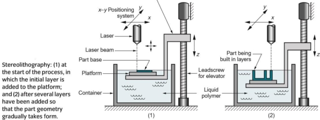
A4) Stereo lithography: It is an additive manufacturing process in which the starting materials are liquid monomers. Polymerization occurs upon exposure to ultraviolet light produced by helium-cadmium or argon ion lasers. Scan speeds of STL lasers typically range between 500 and 2500 mm/s. The stereo lithography apparatus consists of (1) a platform that can be moved vertically inside a vessel containing the photosensitive polymer, and (2) a laser whose beam can be controlled in the x-y direction.

At the start of the process, the platform is positioned vertically near the surface of the liquid photopolymer, and a laser beam is directed through a curing path that comprises an area corresponding to the base (bottom layer) of the part. This and subsequent curing paths are defined by the STI file. The action of the laser is to harden (cure) the photosensitive polymer where the beam strikes the liquid, forming a solid layer of plastic that adheres to the platform. When the initial layer is completed, the platform is lowered by a distance equal to the layer thickness, and a second layer is formed on top of the first by the laser, and so on. Before each new layer is cured, a wiper blade is passed over the viscous liquid resin to ensure that its level is the same throughout the surface. Each layer consists of its own area shape, so that the succession of layers, one on top of the previous, creates the solid part shape. Each layer is 0.076 to 0.50 mm thick. Thinner layers provide better resolution and allow more intricate part shapes, but processing time is greater. The time required to build the part by this layering process ranges from1 hour for small parts of simple geometry up to several dozen hours for complex parts. Other factors that affect cycle time are scan speed and layer thickness.