Unit - 2
Introduction to Personal Communication Services (PCS)
Q1) Draw and explain the PCS Network Architecture. Also explain their objective?
A1) PCS stands for Personal Communication System. The objective of PCS is to enable communication with a person at any time, at any place & in any form. It also manages their individual call services according to their service by providing unlimited reachability & accessibility. Sprint was the first company to set up a PCS network, which was a GSM-1900 network in the Baltimore-Washington metropolitan area in the USA. PCS promises to provide a wide range of locations and equipment-independent services to a large number of users. According to the definition given by the US Federal Communications Commission (FCC), PCS is the system by which every user can exchange information with everyone, at anytime, in any place, through any type of services, using a single personal telecommunication number (PTN). Key factors of PCS are:
1. Reachability with respect to Location (Home, office, in public, in transit)
1. Accessibility with respect to Device (Cellular phone, wired phone, fax etc.)
2. Management of Service.
Architecture consists of two parts Radio Network PCS users carry mobile stations (MS) to communicate with a BS in a PCS n/w. MS is also referred to as handset or mobile phone. The radio coverage of a base station is called cell. In GSM n/w each cell is controlled by BSC which are connected to MS through BS. The BSCs are connected to MSC by landlines.
Wireline Transport Network
An MSC is a telephone exchange configured specially for mobile applications. It interfaces the MSC (via BS) with PSTN. MSCs are also connected with mobility database to track the location of MS and roaming management. The databases are HLR & VLR. HLR contains the authentication information like IMSI (International Mobile Subscriber Identity), identification information like name, address of the subscriber, billing information like prepaid or post-paid, operator selection, denial of service to a subscriber etc. VLR gives information about the location area of the subscriber while on roaming and power off status of the handset.
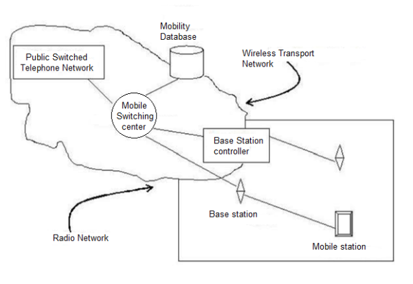
Fig 1 PCS Network Architecture
Q2) What is inter BS hands-off and inter MSC hands-off?
A2) Inter-BS Handoff/ Inter Cell Handoff: Here MS usually moves from one BS to another BS under one MSC. Action taken for communication:
1. The MS momentarily suspends conversation & initiates the hand-off procedure by picking a channel in new BS. Then is resumes the conversation in old BS.
2. When MSC receives that signal, he transfers the information to the new BS & sets up new conversation path to MS through that channel.
3. After MS has been transferred to new BS, it starts the conversation channel with new BS & then MSC disconnect the link with old BS.

Fig 2 Inter-BS link Transfer
Inter-System Handoff/Inter-MSC Handoff
MS moves from one BS to another connected to two different MSCs. Action taken for communication:
1. MSC1 requests MSC2 to perform handoff measurement on the call in progress.
2. MSC2 then selects a BS by interrogating the signal quality and sends the information to MSC1.
3. Then MSC1 asks MSC2 to setup a voice channel.
4. Assuming that a voice channel is available in BS2.MSC2 instructs MSC1 to start radio link transfer. 5. MSC1 sends the MS a handoff order. Now MS can access BS2 of MSC2.MSC2 informs MSC1 that handoff is successful.MSC1 then connects call path to MSC2.
6. In the intersystem handoff process, anchor MSC is always in call path before & after handoff.
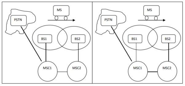
Fig 3 Inter system handoff
Q3) Explain the registration process carried out in PCS systems?
A3) When a mobile user moves from one PCS system to another, then the system should be informed of the current location of the user. Otherwise, it is impossible to deliver services. Two basic operations are performed under roaming management.
1. Registration (location update): Where MS informs the system its current location.
2. Location tracking: Process during which a system locates MS. Location tracking is required when n/w attempts to deliver call to a mobile user. The roaming management follows a two-level strategy where two tier systems of home and visited databases are used. When a user subscribes to the services of a network, a record is created in the system’s database called HLR. This is referred to as home system of the mobile user. HLR is a n/w database, where MS's identity, profile, current location & validation period is stored. When the mobile user visits a new network other than home system, a temporary record for the mobile user is created in the VLR of visited system. VLR temporarily stores information for visiting subscribers so that corresponding MSC can provide service.
Registration Procedure includes following steps:
1. When mobile user enters into new PCS n/w, it must register in VLR of new system.
2. The new VLR informs mobile user's HLR regarding the current location & address of user. The HLR sends an acknowledgement which includes MS's profile, to the new VLR.
3. New VLR informs MS about successful registration.
4. HLR sends a deregistration message to cancel the location record of MS in old VLR. The old VLR acknowledges the deregistration.
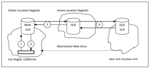
Fig 4 MS Registration Process
To originate a call, MS first contacts with MSC in the new PCS n/w. The call request is forwarded to VLR for approval. If it is approved, MSC sets up the call to the user following the standard PSTN procedures.
1. If a wireline phone attempts to call a mobile subscriber, the call is forwarded to switch called the originating switch in PSTN. The switch masses a query to HLR to find current VLR of MS. The HLR queries the VLR in which MS resides to get a communicable address.
2. The VLR returns the address to switch through HLR.
3. Based on address, a communication link is established between MS through visited MSC.

Fig 5 Call Delivery Procedure
Q4) What is path minimisation? Draw and explain with help of diagram?
A4) Mobility management function handles the function that arises due to mobility of the subscriber. Main objective of MM is location tracking & call set up. There are two aspects of mobility in a PCS n/w.
HANDOFF:
When a mobile user is engaged in conversation, the MS is connected to BS via radio link. If the user moves to the coverage area of another BS, the radio link to old BS is disconnected and radio link to new BS is established to continue conversation. This process is called automatic link transfer or handoff.
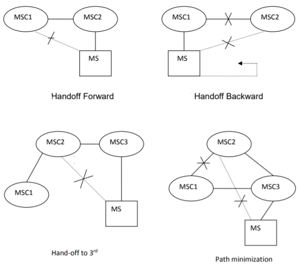
Path Minimization- When MS moves to MSC3, MSC2 may be removed from the call path. The link between MSC1 and MSC2 is disconnected and MS connects to MSC3 directly. This process is called path minimization.
Q5) Explain the SS7 signalling points in details?
A5) All nodes in the SS7 network are called Signalling Points (SPs). Each SP is identified by a unique address called a Point Code (PC). SPs have the ability to read a Point Code and determine if the message is for that node and the ability to route SS7 messages to another SP. Each signalling point in the SS7 network is uniquely identified by a numeric point code. Point codes are carried in signalling messages exchanged between signalling points to identify the source and destination of each message. Each signalling point uses a routing table to select the appropriate signalling path for each message. There are three kinds of signalling points in the SS7 network
- SSP (Service Switching Point or Signal Switching Point)
- STP (Signal Transfer Point)
- SCP (Service Control Point)
Service Switching Point (SSP)
SSPs are switches, for example, Class 5 (local) and Class 4 (tandem) with SS7 interfaces. SSPs convert global title digits (i.e., a dialled number) from a subscriber line to SS7 signalling messages. SSPs setup, manage and release voice circuits required to make a call. SSPs send messages using the ISDN User Part (ISUP) and Transaction Capabilities Application Part (TCAP) protocols to summarize, an SSP’s function is to use a global title to determine how to connect a call using its routing table.
Signal Transfer Point (STP): An STP is a router and/or a gateway in the SS7 network. Messages are not originated by an STP. STPs switch SS7 messages between signalling points. If an originating SSP does not know the address of a destination SSP, the STP must provide it using Global Title Translation. Gateway STPs serve as the interface into another network and they can provide protocol conversion. STPs also provide traffic and usage measurements.
Service Control Point (SCP) An SCP provides application access. It is an interface to applications such as databases. An SCP communicates with applications using primitives. A primitive is an interface that provides access from one level of a protocol to another level. The protocol used to access and interface a database application is TCAP.
SS7 Signalling Links:
All SPs (signalling points) are connected using (typically) pairs of Links. Each Link type is identified with a letter as defined below:
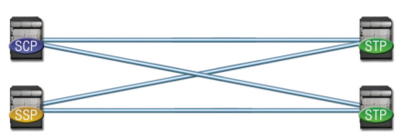
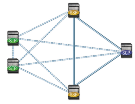
Type A—Access Links (used to connect SSPs to STPs or STPs to SCPs)
An “A” (access) link connects a signalling end point (for example, an SCP or SSP) to an STP. Only messages originating from or destined to the signalling end point are transmitted on an A link.
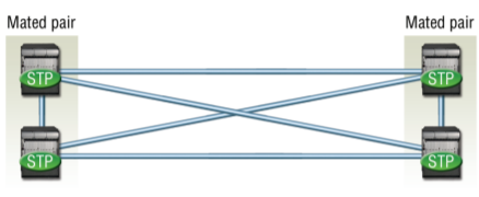
Type B—Bridge Links (used to connect paired STPs to other paired STPs).
A “B” (bridge) link connects an STP to another STP. Typically, a quad of “B” links interconnect peer (or primary) STPs (for example, the STPs from one network to the STPs of another network). The distinction between a B link and a D link is rather arbitrary. For this reason, such links may be referred to as B/D links
Type C—Cross Links (used to connect paired STPs)
A “C” (cross) link connects STPs performing identical functions into a mated pair. A C link is used only when an STP has no other route available to a destination signalling point due to link failure(s). Note that SCPs may also be deployed in pairs to improve reliability; unlike STPs, however, mated SCPs are not interconnected by signalling links.
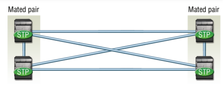
Type D—Diagonal Links (used to connect paired STPs at one in the hierarchy to paired STPs at another level in the hierarchy)
A “D” (diagonal) link connects a secondary (local or regional) STP pair to a primary (for example, inter-network gateway) STP pair in a quad-link configuration. Secondary STPs within the same network are connected via a quad of D links. The distinction between a B link and a D link is rather arbitrary. For this reason, such links may be referred to as B/D links.
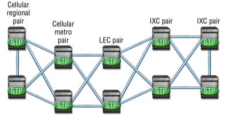
Type E—Extended Links (connects SSPs to alternate or remote STPs for increased resilience and load sharing)
An “E” (extended) link connects an SSP to an alternate STP. E links provide an alternate signalling path if an SSP’s home STP cannot be reached via an A link. E links are not usually provisioned unless the benefit of a marginally higher degree of reliability justifies the added expense.
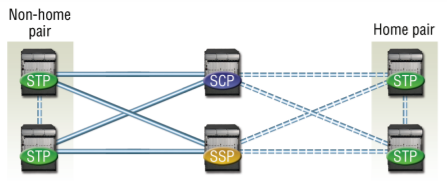
Type F—Fully Associated Links (used to connect SSPs when significant traffic flows between them) An “F” (fully associated) link connects two signalling end points (i.e., SSPs and SCPs). F links are not usually used in networks with STPs. In networks without STPs, F links directly connect signalling points.
Q6) Explain SS7 signalling protocol in detail?
A6) Common channel signalling which provides control and management in the telephone network. CCS consists of supervisory functions, addressing, and providing call information. A CCS channel conveys messages to initiate and terminate calls, check on the status of some part of the network, and control the amount of traffic allowed. CCS uses a separate out-of-band signalling network to carry signalling messages. In all figures of this article, the signal links will be represented by dashed lines, and the trunks will be represented by solid links. SS7 is a CCS system developed to satisfy the telephone operating companies’ requirements for an improvement to the earlier signalling systems (which lacked the sophistication required to deliver much more than Plain Old Telephone Service or POTS). This section provides a brief introduction to the SS7 network architecture and protocol from the perspective of PCN interconnection
Figure below illustrates an example of the SS7 signalling network. The figure only shows the parts that involve the interconnection between a PCN and the PSTN. The network consists of three distinct components.
*Service Switching Point (SSP) is a telephone switch interconnectedbySS7links.TheSSPsperformcallprocessingoncalls that originate, tandem, or terminate at that node. In this article, an SSP in a PCN are called a Mobile Switching Center (MSC).
*Signal Transfer Point (STP) is a switch that relays SS7 messages between network switches and databases. Based on the address fields of the SS7 messages, the STPs route the messages to the correct outgoing signalling links. To meet the stringent reliability requirements, STPs are provisioned in mated pairs. Service Control Point (SCP) contains databases for providing enhanced services. An SCP accepts queries from an SSP and returns the requested information to the SSP. In mobile.
Applications, an SCP may contain an HLRor a VLR. There are six types of SS7 signalling links. Two types of the links are introduced in this article. Each SSP and SCP will have a minimum of one signal link to each STP pair. The signal link is referred to as the Access Link (A-link). The number of A-links between an SSP and an STP pair can be up to 128 though most switch suppliers have limited the number to 16. Signalling links that connect STPs of different networks (e.g., PCN and PSTN in our example) are called Diagonal Links (D-links). D-links are deployed in a quad arrangement with three-way path diversity. The maximum link set size is 64.
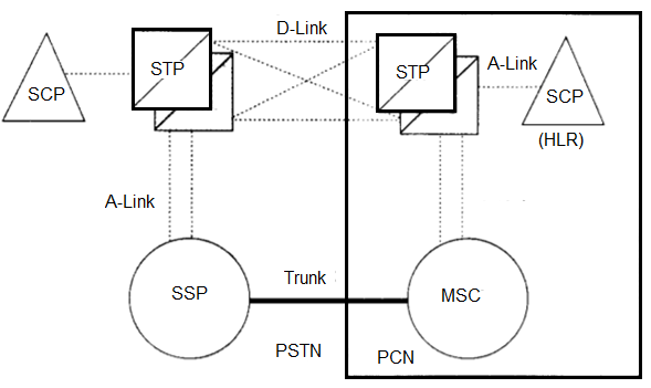
Fig 6 Architecture
The basic parts of the SS7 protocol and the corresponding OS1 layers are shown in Fig. Below. In the protocol hierarchy, the Operations, Maintenance, and Administration Part (OW) and Mobile Application Part (MAP) are TCAP (i.e., Transaction Capabilities Application Part; to be defined) applications. The MAP will be elaborated based on the IS41 protocol. The other parts of the SS7 protocol are described below.
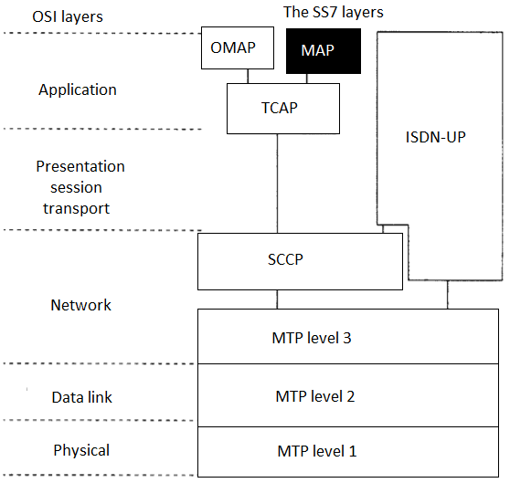
Fig 7 The SS7 signalling protocol
The Message Transfer Part (MTP) consists of three levels corresponding to the OS1 physical layer, data link layer, and network layer, respectively. The MTP Level 1 defines the physical, electrical, and functional characteristics of the signalling links connecting SS7 components. The MTP Level 2 provides reliable transfer of signalling messages between two directly connected signalling points. The MTP Level 3 provides the functions and procedures related to message routing and network management.
- The Signaling Connection Control Part (SCCP) provides additional functions such as Global Title Translation to the MTP to transfer non-circuit-related signaling information such as PCS registration and cancellation.
- The Transaction Capabilities Application Part (TCAP) provides the ability to exchange information between applications using non-circuit related signaling.
- Integrated Services Digital Network User Part (ISUP) establishes circuit-switched network connections (e.g., call setupirelease). Pass-along signaling service sends the signaling information to each switching point involved in a call connection. The IS-41 protocol is implemented in the MAP as an application of the TCAP. The wireless call setup/release is completed by using the ISUP. The MTP and the SCCP provide routing services between a PCN and the PSTN.
Q7) Explain basic cellular system with hexagonal cell structure?
A7)
- The design objective of early mobile radio systems was to achieve a large coverage area using a single, high-powered transmitter with an antenna mounted on a tall tower
- The cellular concept is a system-level idea which calls for replacing a single, high power transmitter (large cell) with many low power transmitter (small cells) each providing a coverage to only a small portion of the service area While it might seem natural to choose a circle to represent the coverage of a BS, adjacent circles cannot be overlaid upon a map without leaving gaps or creating overlapping regions Thus when considering geometric shapes which cover an entire region without overlap and with equal area, there are three sensible choices – a square, an equilateral triangle and a hexagon
- The actual radio coverage of a cell is known as footprint and is determined from field measurements or propagation prediction models
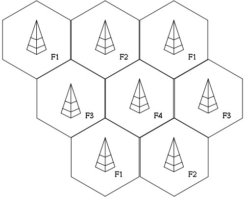
Fig 8. The Cellular Model
- Why hexagon for theoretical coverage?
- For a given distance between the center of a polygon and its farthest perimeter points, the hexagon has the largest area of the three
- Thus, by using hexagon geometry, the fewest number of cells can cover a geographic region, and hexagon closely approximates a circular radiation pattern which would occur for an omnidirectional BS antenna and free space propagation
- When using hexagons to model a coverage area, BS transmitters are depicted as either being in the center of the cell (center-excited cells) or on the three of the six cell vertices (edge-excited cells)
- Normally omnidirectional antennas are used in center-excited cells and directional antennas are used in corner-excited cells
Q8) Explain the frequency reuse concept in cellular networks?
A8)
- Each cellular BS is allocated a group of radio channels to be used within a
Small geographic area called cell
- BS in adjacent cells are assigned channel groups which contain completely
Different channels than neighbouring cells
- By limiting the coverage area to within the boundaries of a cell, the same
Groups of channels may be used to cover different cells that are separated from
One another by distances large enough to keep the interference levels within
Tolerable limits
- The design process of selecting and allocating channel groups for all of the
Cellular BSs is called frequency reuse or frequency planning

Fig. 9 Cellular Frequency reuse concept
- Cells with the same letter use the same set of frequencies.
- A cell cluster is outlined in bold.
- In this Example, the cluster size is N equal to 7 and frequency reuse factor is 1/N=1/7
Q9) Explain in detail the cell splitting phenomenon in cellular systems?
A9) The concept of Cell Splitting is quite self-explanatory by its name itself. Cell splitting means to split up cells into smaller cells. The process of cell splitting is used to expand the capacity (number of channels) of a mobile communication system. As a network grows, a quite large number of mobile users in an area come into picture. Consider the following scenario.
There are 100 people in a specific area. All of them owns a mobile phone (MS) and are quite comfortable to communicate with each other. So, a provision for all of them to mutually communicate must be made. As there are only 100 users, a single base station (BS) is built in the middle of the area and all these users’ MS are connected to it. All these 100 users now come under the coverage area of a single base station. This coverage area is called a cell. This is shown in Figure.
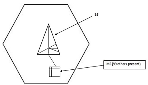
Fig.10 A single BS for 100 MS users.
But now, as time passed by, the number of mobile users in the same area increased from 100 to 700. Now if the same BS has to connect to these 700 users’ MS, obviously the BS will be overloaded. A single BS, which served for 100 users is forced to serve for 700 users, which is impractical. To reduce the load of this BS, we can use cell splitting. That is, we will divide the above single cell into 7 separate adjacent cells, each having its own BS. This is shown in Fig below.

Fig.11 Single cell split up into 7 cells.
Now, let us look into the big picture. Until now, we have discussed about cell splitting in a small area. Now, we use this same concept to deal with large networks. In a large network, it is not necessary to split up all the cells in all the clusters. Certain BSes can handle the traffic well if their cells (coverage areas) are split up. Only those cells must be ideal for cell splitting. Fig below shows network architecture with a few numbers of cells split up into smaller cells, without affecting the other cells in the network.
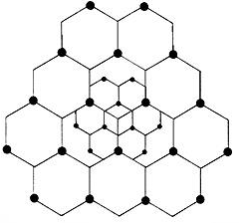
Fig.12 Cell Splitting
The concept of cell splitting can further be applied to the split cells as well. That is, the split-up cells can further be split into a number of smaller cells to improve the efficiency of the BS even more. Fig above shows a hierarchy of cell splitting.

Fig.13 Cell Splitting of Split up cells.
Here, the master cells which have been split up into smaller cells are known as macro cells. The split-up cells are known as micro cells. The innermost cells, split up by splitting the micro cells are known as pico cells.
Q10) How co-channel interference can be decreases in cellular telephone systems?
A10) In cellular telephone system, co-channel interference can be decreased by replacing a single omnidirectional antenna with several directional antennas, each radiating within a smaller area.
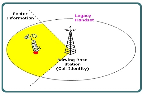
Fig.14 Cell Sectoring
Another way of improving the channel capacity of a cellular system is to decrease the D/R ratio while keeping the same cell radius. Improvement in the capacity can be accomplished by reducing the number of cells in a cluster, hence increasing the frequency reuse. To achieve this, the relative interference must be minimized without decreasing the transmit power.
For minimizing co-channel interference in a cellular network, a single Omni-directional antenna is replaced with multiple directional antennas, with each transmitting within a smaller region. These smaller regions are called sectors and minimizing co-channel interference while improving the capacity of a system by using multiple directional antennas is called sectoring.
The amount up to which co-channel interference is minimized depends on the amount of sectoring used. A cell is generally divided either into three 120 degree or six 60-degree sectors. In the three-sector arrangement, three antennas are generally located in each sector with one transmit and two receive antennas.
When sectoring technique is used in cellular systems, the channels used in a particular sector are actually broken down into sectored groups, which are only used inside a particular sector. With 7-cell reuse pattern and 120-degree sectors, the number of interfering cells in the neighbouring tier is brought down from six to two.
Cell sectoring also improves the signal-to-interference ratio, thereby increasing the capacity of a cellular system. This method of cell sectoring is very efficient, because it utilized the existing system structures.
Cell sectoring also minimized the co-channel interference, with the use
Of directional antennas, a particular cell will get interference and transmit only a fraction of the available co-channel cells.
Q11) What are repeaters and how they are used for range extension?
A11) Repeaters for rang extension
A wireless repeater (also called wireless range extender) takes an existing signal from a wireless router or access point and rebroadcasts it to create a second network. When two or more hosts have to be connected with one another and the distance is too long for a direct connection to be established, a wireless repeater is used to bridge the gap. It can be a specialized standalone computer networking device. Wireless repeaters are commonly used to improve signal range and strength within homes and small offices.
Wireless operators want to provide dedicated coverage for users located within buildings, or in valleys or tunnels as these areas are sometimes very hard to reach. Radio retransmitters, also known as repeaters, are frequently used to provide coverage in such areas where range extension capabilities are required. Repeaters are bidirectional devices, as the signals can be concurrently transmitted to and received from a base station.
Repeaters may be installed anywhere as they function using over the air signals, and are able repeat entire frequency band. After receiving signals from base station, the repeater amplifies the signals before it forwards them to the coverage area.
As repeaters can also reradiate the received noise, so repeaters must be installed very carefully. Directional antennas or distributed antenna system (DAS) are linked practically to the repeater inputs or outputs for spot coverage, mainly in tunnels or buildings.
Q12) What are microcells explain in detail?
A12) Microcell Zone Concept
The micro-cell zone concept is associated with sharing the same radio equipment by different micro-cells. It results in decreasing of cluster size and, therefore, increase in system capacity. The micro-cell zone concept is used in practice to improve the capacity of cellular systems.
To improve both capacity and signal quality of a cellular system, cell sectoring depends upon correct setting up of directional antennas at the cell-site. But it also gives rise to increase in the number of handoffs and trunking inefficiencies. In a 3-sector or 6-sector cellular system, each sector acts like a new cell with a different shape and cell.
Channels allocated to the un-sectored cell are divided between the different sectors present in a cell, thereby decreasing number of channels available in each sector. Furthermore, handoff takes place every time a mobile user moves from one sector to another sector of the same cell.
This results in significant increase of network load on BSC and MSC of the cellular system. The problem of channel partitioning and increase in network load become very hard if all the 3 or 6-sectored directional antennas are placed at the centre of the cell.
As shown in the Fig., three directional antennas are put at a point, Z1, also called zone-site, where three adjacent cells C1, C2, and C3 meet with each other. Z1, Z2 and Z3 are three zone-sites of the cell C1, and each zone-site is using three 135 degree directional antennas. All the three zone-sites also behave as receivers, which also receive signals transmitted by a mobile user present anywhere in the cell.
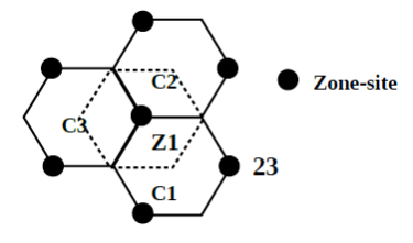
Fig.15 Location of zone site in sectored cell
All the three zone-sites are linked to one common base station, as shown in Fig. This arrangement is known as Lee's micro-cell zone concept
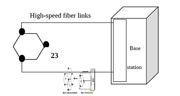
Fig. 16 Lee’s Microcell zone concept
Q13) Compare FDM and TDM techniques?
A13) Differentiate between FDM and TDM
Sr. No. | FDM | TDM |
1. | Total frequency bands are divided into several users. | Time is divided into several no. Of users. |
2. | Transmission via different frequency bands for each signal. | Transmission of signal via same path at different times irrespective of no. Of signal. |
3. | Signals are multiplexed arrived from no. Of sources. | Bandwidth used to connect channel to node with finite set of time slots. |
4. |
|
|
Q14) Explain the three types of channel allocation strategies?
A14) There are three types of strategies that are followed
- Fixed Channel Allocation,
- Dynamic Channel Allocation and
- Hybrid Channel Allocation which is a combination of the first two methods.
Fixed Channel Allocation
Fixed Channel Allocation (FCA) systems allocate specific channels to specific cells. This allocation is static and cannot be changed. For efficient operation, FCA systems typically allocate channels in a manner that maximizes frequency reuse. Thus, in a FCA system, the distance between cells using the same channel is the minimum reuse distance for that system. The problem with FCA systems is quite simple and occurs whenever the offered traffic to a network of base stations is not uniform.
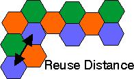
Fig. 17 Reuse Distance
Consider a case in which two adjacent cells are allocated N channels each. There clearly can be situations in which one cell has a need for N+k channels while the adjacent cell only requires N-m channels (for positive integers k and m). In such a case, k users in the first cell would be blocked from making calls while m channels in the second cell would go unused. Clearly in this situation of non-uniform spatial offered traffic, the available channels are not being used efficiently. FCA has been implemented on a widespread level to date.
Dynamic Channel Allocation
Dynamic Channel Allocation (DCA) attempts to alleviate the problem mentioned for FCA systems when offered traffic is non-uniform. In DCA systems, no set relationship exists between channels and cells. Instead, channels are part of a pool of resources. Whenever a channel is needed by a cell, the channel is allocated under the constraint that frequency reuse requirements cannot be violated. There are two problems that typically occur with DCA based systems.
- First, DCA methods typically have a degree of randomness associated with them and this leads to the fact that frequency reuse is often not maximized unlike the case for FCA systems in which cells using the same channel are separated by the minimum reuse distance.
- Secondly, DCA methods often involve complex algorithms for deciding which available channel is most efficient. These algorithms can be very computationally intensive and may require large computing resources in order to be real-time.
Hybrid Channel Allocation Schemes
The third category of channel allocation methods includes all systems that are hybrids of fixed and dynamic channel allocation systems. Several methods have been presented that fall within this category and in addition, a great deal of comparison has been made with corresponding simulations and analyses
Channel Borrowing is one of the most straightforward hybrid allocation schemes. Here, channels are assigned to cells just as in fixed allocation schemes. If a cell needs a channel in excess of the channels previously assigned to it, that cell may borrow a channel from one of its neighbouring cells given that a channel is available and use of this channel won't violate frequency reuse requirements. Note that since every channel has a predetermined relationship with a specific cell, channel borrowing (without the extensions mentioned below) is often categorized as a subclass of fixed allocation schemes. The major problem with channel borrowing is that when a cell borrows a channel from a neighbouring cell, other nearby cells are prohibited from using the borrowed channel because of co-channel interference. This can lead to increased call blocking over time. To reduce this call blocking penalty, algorithms are necessary to ensure that the channels are borrowed from the most available neighbouring cells; i.e., the neighbouring cells with the most unassigned channels.
Rules for channel assignment
Do not assign co-channels or adjacent channels at the same cell site (not applicable for CDMA).
Do not assign co-channels in adjacent cell sites (not applicable for CDMA).
Do not mix and match channel groups in a cell or sector.
Avoid adjacent channel assignment in adjacent cell sites (not applicable for CDMA).
Maintain proper channel separation for any channel assignment for a sector or site.
Maximize the distance between reusing cell sites
Q15) What is co-channel interference and adjacent channel interference in cellular networks explain in detail?
A15) Co-channel interference
Co-channel interference or CCI is crosstalk from two different radio transmitters using the same frequency.
Co-channel interference occurs between two access points (APs) that are on the same frequency channel. The reason that you should care is that co-channel interference can severely affect the performance of your wireless LAN (WLAN).
Co-channel interference is more problematic when you deploy your WLAN to support voice or RFID location tagging. These types of scenarios require a denser deployment of APs. Denser deployments mean that your APs are closer together. And that creates a greater potential of two devices that transmit on the same frequency channel will be close enough to cause significant interference to each other's signals.
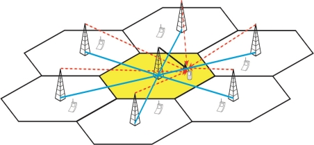
Fig 18 Co-channel interference
Adjacent channel Interference
Adjacent-channel interference (ACI) is interference caused by extraneous power from a signal in an adjacent channel.
Adjacent channel interference (ACI) is interference between links that communicate geographically close to each other using neigh boring frequency bands. For instance, several network operators may deploy their own networks in the same area and operate on frequency bands that are close to each other. Hence, ACI needs to be taken into account in the system specifications so that it will not hamper the system performance.
Adjacent channel interference: interference from adjacent in frequency to the desired signal.
– Imperfect receiver filters allow nearby frequencies to leak into the passband
– Performance degrades seriously due to near-far effect.

Fig 19 Adjacent channel
Adjacent channel interference can be minimized through careful filtering and channel assignment.
• Keep the frequency separation between each channel in a given cell as large as possible
• A channel separation greater than six is needed to bring the adjacent channel interference to an acceptable level.
Q16) What are the cause of co-channel interference explain all of the in detail?
A16) There can be several causes of co-channel radio interference; four examples are listed here.
- Cellular Mobile Networks:
In cellular mobile communication (GSM & LTE Systems, for instance), frequency spectrum is a precious resource which is divided into non-overlapping spectrum bands which are assigned to different cells (In cellular communications, a cell refers to the hexagonal/circular area around the base station antenna). However, after certain geographical distance, the frequency bands are re-used, i.e., the same spectrum bands are reassigned to other distant cells. The co-channel interference arises in the cellular mobile networks owing to this phenomenon of Frequency reuse. Thus, besides the intended signal from within the cell, signals at the same frequencies (co-channel signals) arrive at the receiver from the undesired transmitters located (far away) in some other cells and lead to deterioration in receiver performance.
- Adverse weather conditions:
During periods of uniquely high-pressure weather, VHF signals which would normally exit through the atmosphere can instead be reflected by the troposphere. This tropospheric ducting will cause the signal to travel much further than intended; often causing interference to local transmitters in the areas affected by the increased range of the distant transmitter.
- Daytime vs Night time:
In the Medium frequency portion of the radio spectrum where most AM broadcasting is allocated, signals propagate full-time via groundwave and, at night time, via sky wave as well. This means that during the night time hours, co-channel interference exists on many AM radio frequencies due to the medium waves reflecting off the ionosphere and being bounced back down to earth. In the United States, Canada, Mexico, and the Bahamas, there are international agreements on certain frequencies which allocate "clear-channel" broadcasting for certain stations to either have their respective frequencies to themselves at night, or to share their respective frequencies with other stations located over hundreds or even thousands of miles away. On other frequencies, there are "Regional Channels" where most stations on these frequencies either reduce power or change to a directional antenna system at night time to help reduce co-channel interference to each other's signals. In the United States, there are six "Local Channel" frequencies, also known as "grave yarders" where nearly every station on those frequencies has the same power and antenna pattern both day and night and, as a result of sky wave propagation, there is normally massive co-channel interference in rural areas on these frequencies, often making it difficult, if not impossible, to understand what's being said on the nearest local station on the respective channel, or the other distant stations which are bouncing on the same channel, during the night time hours.
Q17) What are CDMA 2000 standards explain them in detail?
A17)
- It is developed by Third Generation Partnership Project 2 (3GPP2).
- AR1B, TTC (Japan), CWTS (China), TTA (Korea), TIA (North Amerika) companies contributed in development from CDMA one to CDMA 2000 with maintaining backward compatibility with IS-95 B.
- Some of evolution of CDMA 2000 are 1x EV-DO stands for “1x Evolution Data Only” 1x EV-DV stands for “1x Evolution for Data and Voice”.
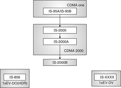
Fig. 20: Overall CDMA 2000 standards
EV-DV
1x EV-DV provides some benefits like :
- Pick data rate 3.1 Mbps per sector.
- Support provided to real-time and non-real time both.
- Seamless backward compatibility.
- Same carrier utilized to support voice of data features.
- High forward link capacity.
- Voice service and concurrent voice/data support.
- Backward compatibility to 15-95 CDMA 2000.
- Multiple concurrent traffic types (i.e. FPDPH).
- Efficient support of all data services (e.g., V0 IP).
- Same new channels introduced are :
F-PDCH, F-PDCCH, R-ACKCH and R-CQICH.
FPDCH
It stands for Forward Packet Data Channel. It is main channel, 1 channel/sector. It carries Data as well as L3 signalling.
F-PDDCH
It stands for Forward Packet Data Control Channel. It used to transmit demodulate decode, ARQ information to specific mobile 2 channel/sector exists.
R-ACKCH
It stands for reverse acknowledgement channel. ACK/NAK feedback for hybrid ARQ.
R-CQICH
It stands for Reverse Channel Quality Indicator Channel. It provides feedback which is further used as forward link modulation, scheduling and coding etc.
Lx-EV-D0
EV-D0 has Rev 0, Rev A, Rev B such three revisions.
Revision A has 3.1 MBPS peak data rate on downlink and 1.8 MBPS peak data rate on uplink. It support low latency application.
Revision B improved to achieve higher data rates than Rev A. It support multiple carriers Rev B. It has two upgrades : EV-D0 advanced and EV-D0 Rev. C (Revision C).
Table: EV-D0 summary
CDMA 2000 1x E V-D0 release/revision | Max downlink data rate | Max uplink data rate |
Rev. 0 | 2.4 Mbps (300-600 Kbps) | 153.4 Kbps (70-90 kbps) |
Rev. A | 3.1 Mbps (600-1400 kbps) | 1.8 mbps (500-800 kbps) |
Rev. B (Software) | 9.3 Mbps | 5.4 Mbps |
D0 Rev B (Hardware) | 14.7 Mbps | 5.4 Mbps |
D0 Advanced | 19.6 Mbps | 7.2 Mbps |
Q18) Compare CDMA and GSM?
A18)
| CDMA | GSM |
Stands for | Code Division Multiple Access | Global System for Mobile communication |
Storage Type | Internal Memory | SIM card (subscriber identity module) |
Global market share | 25% | 75% |
Dominance | Dominant standard in the U.S. | Dominant standard worldwide except the U.S. |
Data transfer | EVDO/3G/4G/LTE | GPRS/E/3G/4G/LTE |
Network | There is one physical channel and a special code for every device in the coverage network. Using this code, the signal of the device is multiplexed, and the same physical channel is used to send the signal. | Every cell has a corresponding network tower, which serves the mobile phones in that cellular area. |
International roaming | Less Accessible | Most Accessible |
Frequency band | Single (850 MHz) | Multiple (850/900/1800/1900 MHz) |
Network service | Handset specific | SIM specific. User has option to select handset of his choice. |
Q19) What is soft capacity calculation in CDMA technology explain?
A19) The number of customers or the amount of service which any system can provide is called its capacity. The CDMA has soft capacity as the system operator can change the defined level of service to change the maximum number of customers. That can obtain service from the system. This helps the service provider to increase temporarily the system capacity in exchange for a reduction in the quality of voice. By increasing the speech compression and reducing the audio quality a CDMA service provider can increase the number of customers in CDMS mobile communication. The data rate per user is reduced and maximum number of users increases. The reduction in data rate reduces the interference.
The soft capacity limit for gradual decay of voice quality is shown below. The voice quality decays gradually as the number of users increases. The lower bit rates are provided in order to increase the number of users than the capacity limit. As a result, assigning lower bit rates to users as service demand increases trade off voice quality for increases in system capacity.
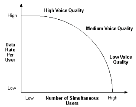
Fig 21 Soft Capacity
Q20) Compare all the multiple access techniques?
A20)
Approach | TDMA | FDMA | CDMA |
Idea | Segment sending time into disjoint time-slots, demand driven or fixed patters | Segment the frequency band into disjoint sub-bands | Spread the spectrum using orthogonal codes
|
Terminals | All terminals are active for short periods of time on the same frequency | Every terminal has its own frequency. Uninterrupted | All terminals can be active at the same place at the same moment uninterrupted. |
Signal separation | Synchronization in the time domain | Filtering in the frequency domain | Code plus special receivers |
Advantages | Established, fully digital, flexible | Simple, established robust | Flexible, less frequency planning needed, soft handover |
Disadvantages | Guard space needed (multipath propagation), synchronization difficult | Inflexible, frequencies are a scarce resource | Complex receivers, needs more complicated power control for senders |
Comment | Standard in fixed networks, together with FDMA/SDMA used in many mobile networks | Typically combined with TDMA (frequency hopping patterns) and SDMA (frequency reuse) | Still faces some problems, higher complexity, lowered expectations: will be integrated with TDMA/FDMA |
