BEE
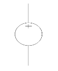
Unit – 1DC Circuits Q1) What is an ideal and practical voltage source?A1) A voltage source is a device which provides a constant voltage to load at any instance of time and is independent of the current drawn from it. This type of source is known as an ideal voltage source. Practically, the ideal voltage source cannot be made. It has zero internal resistance. It is denoted by this symbol.
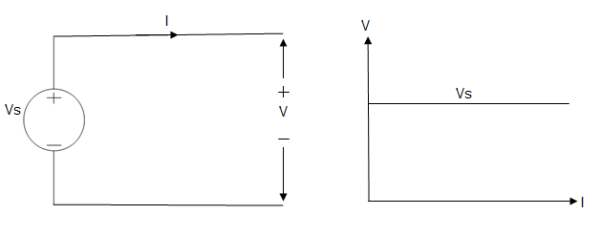
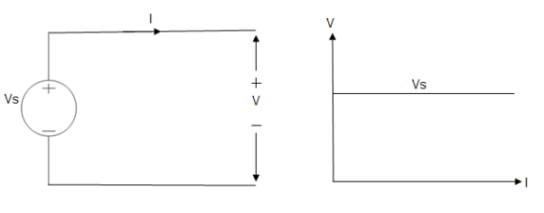
Fig: Voltage source symbol Ideal Voltage Source
Fig: Ideal Voltage Source The graph represents the change in voltage of the voltage source with respect to time. It is constant at any instance of time.Voltage sources that have some amount of internal resistance are known as a practical voltage source. Due to this internal resistance, voltage drop takes place. If the internal resistance is high, less voltage will be provided to load and if the internal resistance is less, the voltage source will be closer to an ideal voltage source. A practical voltage source is thus denoted by a resistance in series which represents the internal resistance of source. Practical Voltage source
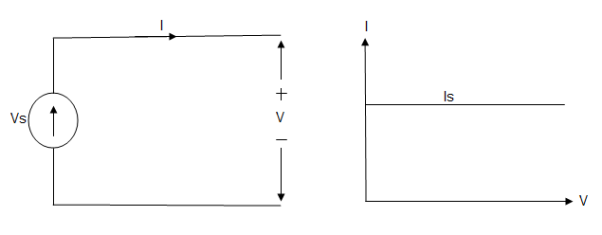
Fig: Practical Voltage source The graph represents the voltage of the voltage source with respect to time. It is not constant but it keeps on decreasing as the time passes. Q2) What is an ideal and practical current source?A2) A current source is a device which provides the constant current to load at any time and is independent of the voltage supplied to the circuit. This type of current is known as an ideal current source; practically ideal current source is also not available. It has infinite resistance. It is denoted by this symbol.Ideal Current source
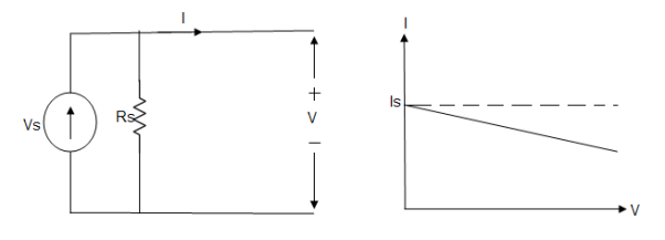
Fig: Ideal Current source The graph represents the change in current of the current source with respect to time. It is constant at any instance of time. Practical Current sourcePractically current sources do not have infinite resistance across there but they have a finite internal resistance. So the current delivered by the practical current source is not constant and it is also dependent somewhat on the voltage across it.A practical current source is represented as an ideal current source connected with resistance in parallel.
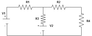
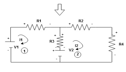
Fig; Practical Current source The graph represents the current of the current source with respect to time. It is not constant but it also keeps on decreasing as the time passes. Q3) Why ideal Current source has infinite resistance?A3) A current source is used to power a load, so that load will turn on. We try to supply 100% of the power to load. For that, we connect some resistance to transfer 100% of power to load because the current always takes the path of least resistance. So, in order for current to go to the path of least resistance, we must connect resistance higher than load. This is why we have the ideal current source to have infinite internal resistance. This infinite resistance will not affect voltage sources in the circuit. Given Circuit
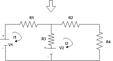
First identify no of loops and assign direction of current flowing in loop Solution:Note : no of loops in circuit = No, of unknown currents = no, of equations in the circuit
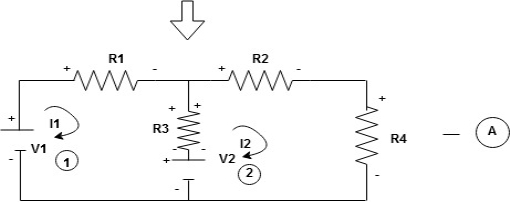
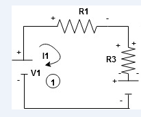
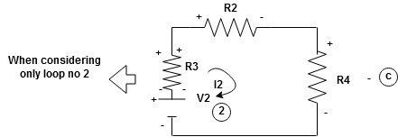
Note : keep loop direction and current direction same ie either clockwise or anticlockwise for all loops I1 I2Now according to direction of direction assign signs (+ve to –ve) to the resistors
Note : voltage sources (V) polarities does not change is constant.Note: for common resistor between 2 loops appearing in the circuit like R3 give signs according to separate loops as shown
When considering only loop no 1 (+ R3 - ) - B
Now consider diagram A and write equations Two loops  two unknown currents
  two equation Apply KVL for loop ① [B. Diagram ](+ to drop -) = - sign and (- to rise +) = + sign
 for drop = -sign
 for rise = + sign
-( ) R2 is considered because in R3,2 currents are flowing
  and
and  and we have taken (
 ) because we are considering loop no 1 and current flowing is
  in loop no 1
  ) Similarly for loop no. 2 currents flowing is
  resistor R3 it should be
  )R3
)R3
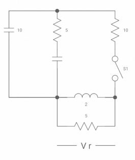
2. Ques: Diagram
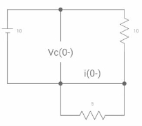
If switch ‘s’ closed at t= 0 find out the voltage across capacitor and current through capacitor at t= 0+?Soln: at t= 0- switch was open so,
:. There is no potential so Vc (0-) = 0At t= 0+, Vc (0-) = Vc (0+) = 0Diagram
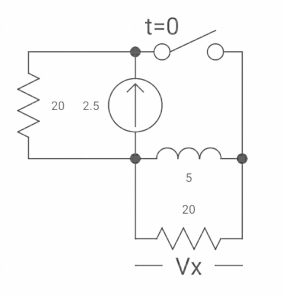
Isc = 10/5 = 2 A Q4) Diagram
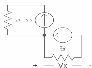
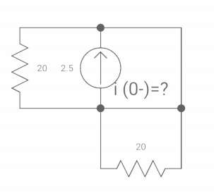
A4) The switch was closed for long time beforeOpening at t=0- find VX (0+)?(a) 25V (b) 50 V (c)-50V (d) 0VSolution:n at time t=0-
clearly, il (0-) = 2.5 Aat t= 0+, as inductor is initially chargesso il (0-) = il (0+)
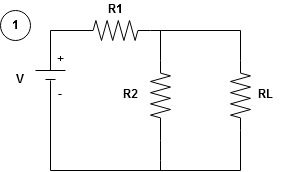
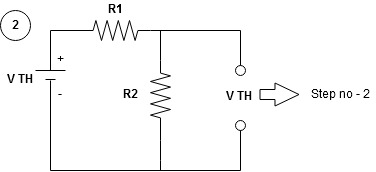
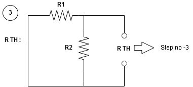
Q5) Explain the Step to apply Thevenin’s theorem.A5) Remove the branch impedance through which current is required to be calculatedCalculate the voltage across the open circuit terminals by using and one of the n/w simplification technique. This voltage is Thevenins equivalent voltage VTH.Calculate the equivalent resistance req. through 2 terminals of the branch from which current is to be calculate by removing load resistance RL and S.C. Vtg. Source and open circuit current source.Draw the Thevenins equivalent showing the vtg. Source VTH with RTH or req. in series with it across the terminals of branch through which current is to calculated (Fig A). the required current in branch is given by L =
L = 
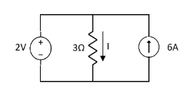
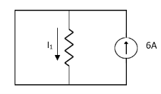
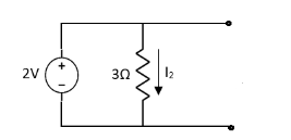
Q6) Find the current through  resistance.A6)
Solution:
 1= 0
1= 0
Special Case:
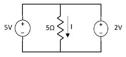
Since two voltage sources with different magnitude in parallel which cannot be connected as in single branch two different current is not possible (if 5V than I = zero).Q7) Find maximum power delivered is RLif its value is
16Ω  Ω
Ω60Ω 20Ω S7)
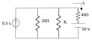
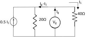
Q8)
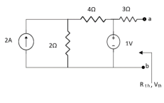
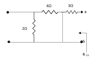
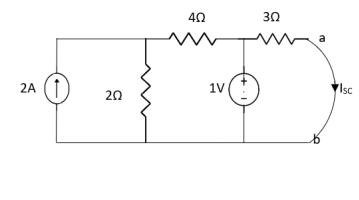
A8)
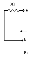
Also, clear from circuit that Vth = 1V.
By applying KVL we get,
|
|
|
|
|
|
|
|
|
|
 two unknown currents
  two equation Apply KVL for loop ① [B. Diagram ](+ to drop -) = - sign and (- to rise +) = + sign
 for drop = -sign
 for rise = + sign
 - |
 ) R2 is considered because in R3,2 currents are flowing
  and
and  and we have taken (
 ) because we are considering loop no 1 and current flowing is
  in loop no 1
  ) Similarly for loop no. 2 currents flowing is
  resistor R3 it should be
  )R3
)R3
|
Consider loop no. 1 apply KVL - - Consider loop no. 2 apply KVL - - After solving equation ① and ② we will get branch current |
|
|
|
|
|
|
-VX= 20/2.5 20*2.5 VX= -50A |
 L =
L = 
|
|
|
 resistance.A6)
|
|
 1= 0
1= 0
|
| |
| |
|
|
 Ω
Ω
|
| ||||
| ||||
Therefore, | ||||
|
|
|
|
1-3Isc=0 Isc= |
0 matching results found
