Unit – 2
Orthographic Projections
Q1) Write a brief note on the principle of Orthographic Projections?
A1) Theory of orthographic projection:
Let us suppose that a transparent plane has been set up between an object and the station point of an observer's eye (Fig. 1). The intersection of this plane with the rays formed by lines of sight from the eye to all points of the object would give a picture that is practically the same as the image formed in the eye of the observer. This is perspective projection.
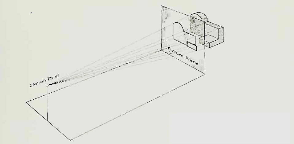
Figure Perspective projection. The rays of the projection converge at the station point from which the object is observed.
Q2) What is the different method of projection?
A2) Following four methods of projection are commonly used,
1) Orthographic projection.
2) Isometric projection.
3) Oblique projection.
4) Perspective projection.
In the above methods 2, 3 and 4 represent the object by a pictorial view as eyes see it. In these methods of projection, a three-dimensional object is represented on a projection plane by one view only, while in the orthographic projection an object is represented by two or three views on the mutual perpendicular projection planes. Each projection view represents two dimensions of an object. For the complete description of the three-dimensional object at least two or three views are required.
Q3) Explain what is the principle of Auxiliary Planes?
A3) A straight line is the shortest distance between two points. Hence, the projections of a straight line may be drawn by joining the respective projections of its ends which are points.
The position of a straight line may also be described with respect to the two reference planes. It may be:
1. Parallel to one or both the planes.
2. Contained by one or both the planes.
3. Perpendicular to one of the planes.
4. Inclined to one plane and parallel to the other.
5. Inclined to both the planes.
6. Projections of lines inclined to both the planes.
7. Line contained by a plane perpendicular to both the reference planes.
8. True length of a straight line and its inclinations with the reference planes.
9. Traces of a line.
10. Methods of determining traces of a line.
11. Traces of a line, the projections of which are perpendicular to xy.
12. Positions of traces of a line.
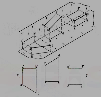
Q4) Describe the process when Line contained by one or both the planes in Orthographic Projections.
A4)
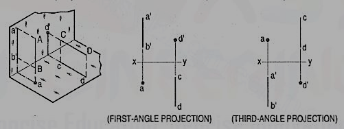
Q5) Describe the process when Line perpendicular to one of the planes in Orthographic Projections.
A5)
Q6) Describe the process when Line inclined to one plane and parallel to the other in Orthographic Projections.
A6)
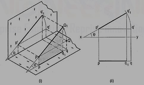
The inclination of a line to a plane is the angle which the line makes with its projection on that plane.
Line PQ1 fig is inclined at an angle 8 to the H.P. and is parallel to the V.P. The inclination is shown by the angle 8 which PQ1 makes with its own projection on the H.P., viz. the top view pq1.
The projections fig. may be drawn by first assuming the line to be parallel to both the H.P. and the V.P. Its front view p'q' and the top view pq will both be parallel to xy and equal to the true length. When the line is turned about the end P to the position PQ1 so that it makes the angle 8 with the H.P. while remaining parallel to the V.P., in the front view the point q' will move along an arc drawn with p' as centre and p'q' as radius to a point q'1 so that p'q'1 makes the angle 8 with xy. In the top view, q will move towards p along pq to a point q1 on the projector through q'1. p'q'1 and pq1 are the front view and the top view respectively of the line PQ1.
Q7) Write down the method when Line inclined to both the planes in Orthographic Projections.
A7) A line AB fig. is inclined at θ to the H.P. and is parallel to the V.P. The end A is in the H.P. AB is shown as the hypotenuse of a right-angled triangle, making the angle θ with the base.
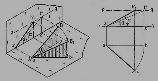
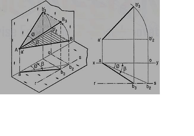
8. The same line AB (fig.) is inclined at ϕ to the V.P. and is parallel to the H.P. Its end A is in the V.P. AB is shown as the hypotenuse of a right-angled triangle making the angle ϕ with the base.
9. The front view a'b'2 is shorter than AB and parallel to xy. The top view ab2 is equal to AB and makes an angle ϕ with xy.
10. Keeping the end, A fixed and the angle ϕ with the V.P. constant, if B is moved to any position, say B3, the line will become inclined to the H.P. also.
11. In the front view, b'2, will move along the arc, drawn with a' as center and a'b'2 as radius, to a position b'3. The new front view a'b'3 is equal to a'b'2 but is shorter than AB.
12. In the top view, b2 will move to a point b3 along the line rs, drawn through b2 and parallel to xy, thus keeping its distance from the path of a, viz. b2o constant. rs is the locus or path of the end B in the top view. The point b3 lies on the projector through b'3. The new top view ab3 is shorter than ab2 (i.e., AB) and makes an angle β with xy. β is greater than ϕ.
13. Here also we find that, if the inclination of AB with the V.P. does not change, even when it becomes inclined to the H.P.
14. (i) its length in the front view, viz. a'b'2 remains constant; and
15. (ii) the distance between the paths of its ends in the top view, viz. b2o remains constant.
16. Hence, when a line is inclined to both the planes, its projections are shorter than the length and inclined to xy at angles greater than the true inclinations. These angles viz. α and β are called apparent angles of inclination.