Unit – 3
Projections of Regular Solids
Q1) Explain the process when Projections of Regular Solids Perpendicular to both the reference planes?
A1) A square ABCD is perpendicular to both the planes. Its H.T. and V.T. are in a straight-line perpendicular to xy.
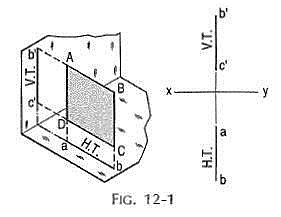
The front view b'c' and the top view ab of the square are both lines coinciding with the V.T. and the H.T. respectively.
Q2) Explain the process when Projections of Regular Solids Perpendicular to one plane and parallel to the other plane?
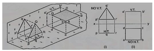
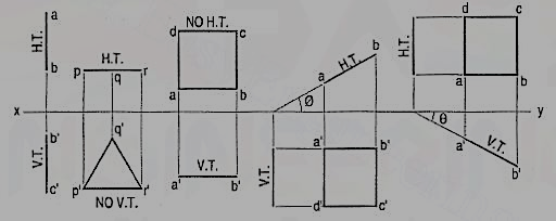
A2) a) Plane, perpendicular to the H.P. and parallel to the V.P. A triangle PQR is perpendicular to the H.P. and is parallel to the V.P. Its H.T. is parallel to xy. It has no V.T.
The front view p'q'r' shows the exact shape and size of the triangle. The top view pqr is a line parallel to xy. It coincides with the H.T.
(b) Plane, perpendicular to the V.P. and parallel to the H.P. A square ABCD is perpendicular to the V.P. and parallel to the H.P. Its V.T. is parallel to xy. It has no H.T.
The top view abed shows the true shape and true size of the square. The front view a'b' is a line, parallel to xy. It coincides with the V.T
Q3) Write the step for Projections of Regular Solids when it is Perpendicular to one plane and inclined to the other plane?
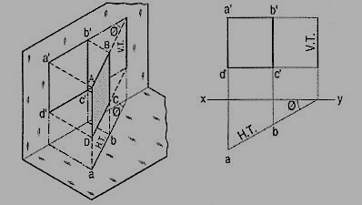
A3) A square ABCD is perpendicular to the H.P. and inclined at an angle φ to the V.P. Its V.T. is perpendicular to xy. Its H.T. is inclined at φ to xy.
Its top view ab is a line inclined at φ to xy. The front view a'b'c'd' is smaller than ABCD.
(b) Plane, perpendicular to the V.P. and inclined to the H.P. (fig. 12-4).
A square ABCD is perpendicular to the V.P. and inclined at an angle θ to the H.P. Its H.T. is perpendicular to xy. Its V.T. makes the angle e with xy. Its front view a'b' is a line inclined at θ to xy. The top view abed is a rectangle which is smaller than the square ABCD.
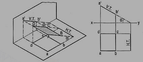
Fig. shows the projections and the traces of all these perpendicular planes by third-angle projection method.
Q4) What are Oblique planes?
A4) Planes which are inclined to both the reference planes are called oblique planes.
Q5) What do you mean by Traces of planes?
A5) A plane, extended if necessary, will meet the reference planes in lines, unless it is parallel to any one of them.
These lines are called the traces of the plane. The line in which the plane meets the H.P. is called the horizontal trace or the H.T. of the plane. The line in which it meets the V.P. is called its vertical trace or the V.T. A plane is usually represented by its traces.
Q6) Draw the Annotation, Dimensioning and Scale of Regular Solids?
A6) The annotative property was added in the AutoCAD 2008 version and it is by far one of the most useful tools of AutoCAD.
Understanding annotative property:
Let us assume a floor plan with maximum exterior dimensions of 525 inches and 336 inches. Now to plot this drawing on a normal A3 size sheet of paper which is 420 X 297 mm we need to decrease the overall scale of drawing to appropriate size.
Let us select a scale of ¼” = 1’ which in layman’s term can be summed up as 0.25 inches on paper equals 1 foot on actual drawing. Now with this scale, the drawing looks like this on A3 paper.
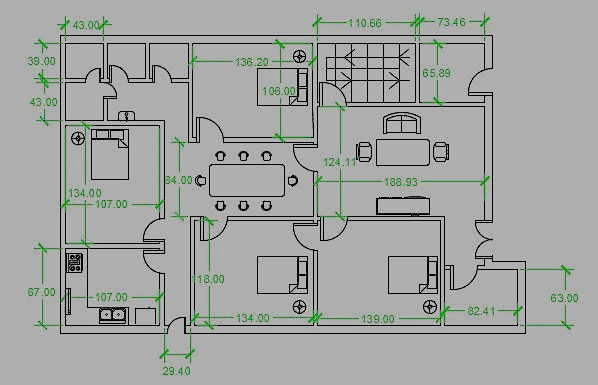
Here all dimensions, text and blocks are clearly visible with respect to the viewport. Now here is another drawing in which only the kitchen is included at a zoomed scale of 1” = 1’
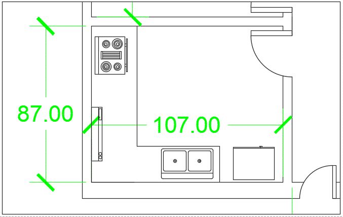
Making Annotative dimension:
To make annotative dimension style type DIMSTYLE on the command line and press enter. A new dimension style manager window will pop up, click on the new button on right side of this window.
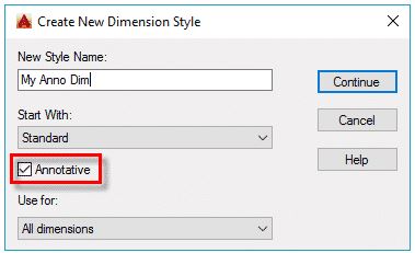
New dimension style window will pop up with multiple tabs, select text tab and change the size of text to 1/8” or whatever paper height of text you want to keep in all scales. Similarly, change arrow size from symbols and arrow tab to 1/8”.
If you already have a dimension style for your drawing and you want to make that style annotative then select your dimension style from dimension style manager then go to fit tab and check the annotative radio button from the scale for dimension features panel.
Adding Scale to Annotative dimensions:
Before preparing the layout for final plotting we should decide the scales in which we want to plot our drawing. Let us assume that we want to plot the drawing on A3 paper size and on three different scales 1” =1’, 1/8” =1’ and ½” =1’.
To make annotative dimensions visible on all these scales, we need to add these scales to the dimensions. From status bar click on add scales… button to turn it on.
For adding scale in an older version of AutoCAD type OBJECTSCALE on the command line and press enter then select all dimensions for which you want to add scales then press enter again. Annotation object scale window will pop up, select add button and add scales to the list and click OK to close all open windows.
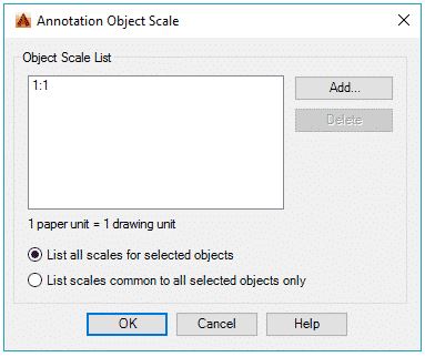
Now click on scale drop down menu next to add scales button and select scale 1” =1’ from the drop-down menu, repeat the process for 1/8” =1’ and ½” =1’ scales also. Now the scales are added to the drawing and our drawing can now be prepared for plotting.
Preparing layout views:
Go to layout tab and type PAGESETUP on the command line and press enter, select modify from page setup manager window and select ISO A3 paper size from the Paper Size drop-down menu of page setup window. Click OK to close page setup window.
Now create three rectangular viewports in paper space and assign scales of 1” =1’, 1/8” =1’ and ½” =1’ to three viewports. You will notice that although we have different drawing components like text, blocks, and geometries on different scales, but the size of dimension text is constant throughout the viewports because of annotative property assigned to them.
If you change the scale of any of these viewports to the value other than the one which is assigned to annotative dimension, then the dimensions will not appear for that scale.
Changing visibility of annotative object:
You can change the position of your annotative object according to the scale. For example, in the scale of 1” =1’ the dimension appears in the middle of the dining table but for a scale of ½” =1’ the dimension may be made to appear outside dining table for the same dimension as shown in figure.
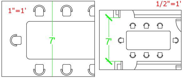
To change the visibility of these objects simply activate viewports by double-clicking within them and move dimensions using grips to the position where you want it to appear for the particular viewport, the position of the annotative object will not change in another viewport.
Q7) Write the method for the projection of Windows, Doors, and Fixtures?
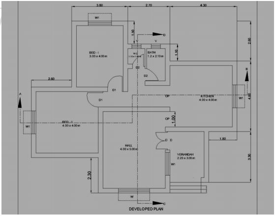
A7) A building may be residential or public building. The plan, section along given vertical plane and elevation gives the details of building.
Plan:
Plan of building represents a horizontal section of building at given height seen from top. It is a general conventional to imagine that the building has been cut down by a horizontal plane at the skill level of the window and is seen from the top after removal of so cut part. The plan shows the arrangement of rooms, varandah or corridor, position of door, and window and other openings along with their respective sizes.
The dimension of the room indicated as Breath x Length In the case of Varandah‟s, the given dimension up to the end of Varandah retaining wall and the position of beams, sunshades, portico, ventilators which are above sill level of window are shown with dotted or broken lines.
Line diagram is the sketch generally not drawn to scale also known as line sketch. The relative positions of all elements like rooms, doors, windows are clearly shown inside to inside. From the given specifications, the thickness of wall in super structure shall be taken to draw the fully dimensioned plan to a convenient scale.
Floor Plan Drawings provide a "bird's-eye view" of the different floor levels of your project. They show scaled dimensions of the project, and include rooms, spaces, walls, partitions, doors, windows, fixtures, and other features.
Section:
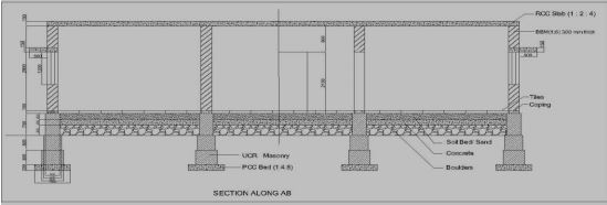
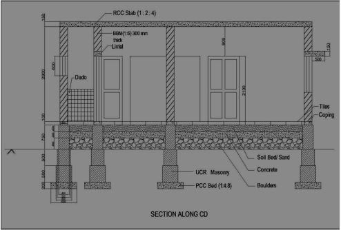
Section is also known as vertical section and sectional elevation or cross section. It is imagined that a finished building is cut vertically along a line so that the building is separated into two portions along the imagined vertical plane right from top of the building to the lowest part of foundation. The view that can be seen while travelling along this imaginary vertical plane when looking towards left is drawn to the same scale as that adopted for the plan.
The line, which is drawn on the plan to indicate the section, is called sectional line and represented by A-B or X-X. The arrow heads shall be marked to indicate the way in which the sectional view is to be drawn. In some cases, offset is given to indicate the necessary details, but the offset is only to shift the vertical plane from one position to another position as shown below.
Typical sectional view
