Unit - 3
Statics
Q1) What is Free Body Diagrams with examples on modelling of typical supports and joints?
A1)
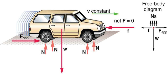
One of the most helpful aids in solving a static problem is the free body diagram (FBD). A free-body diagram is a graphic, dematerialized, and symbolic picture of the body (structure, element, or segment of an element) in which all joining "pieces" have been removed. An FBD is a convenient method of modeling the structure, structural element, or segment under consideration. It is a way of conceptualizing the structure and its composite elements, so that an analysis can be initialized.
All physical attractors are removed from the facility. This is not completed randomly, but with a different method. A body, or a segment of it, is represented by a simple single line. Each connection is exclusively represented by a union with different properties, or is replaced by a series of forces and moments that would represent the action in that connection.
The internal forces that would be in a node (connection or union) can be replaced by representative external forces in which that "part" connects with the other member in the FBD. All charges are represented as force systems.
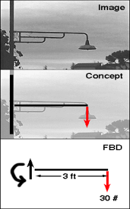
This is a free-body diagram of these three systems that was designed to represent the force system.
Notice how the entire internal structure of this representation has been removed. Internal disposition does not matter for determining support reactions! And, if the support and load geometries are the same, the external reactions will always be the same.
Q2) What are Conditions for Equilibrium in 3 dimension and 2 dimensions?
A2) Conditions for Equilibrium in 3 dimension and 2 dimensions. where ∑→F is the vector sum of entirely the external forces acting on the body and ∑→Mo is the sum of couple moments and moments of all the forces about any point O. 2 dimensions, the equilibrium equations are
∑Fx=∑Fy=∑Mo=0.
Six scalar equations are required to express the conditions for the stability of a rigid body in the general three-dimensional case, those equations are listed below:


These equations can be solved by no more than six unknowns, which will generally represent reactions on supports or connections.
During the solution of most problems, the above scalar equations will be more conveniently obtained if we first express in vector form the conditions for the equilibrium of the rigid body considered.
We write and express the forces "F" and position the vectors "r" with respect to the scalar components and the unit vectors. Next, we calculate all the vector products, either by direct calculation or by determinants.

We note that up to three unknown reaction components can be removed from these calculations by careful choice of the "O" point. By equating the coefficients of the unit vectors in each of the two relations to zero (see the equation above), we obtain the desired scalar equations.
Equilibrium of a particle When the result of all the simultaneous forces acting on a particle is zero, the particle is in a state of equilibrium. This means: ∑Fx = 0 ∑Fy = 0 or Sum of horizontal forces ∑H = 0 Sum of horizontal forces ∑V = 0
Q3) What is Limiting Friction?
A3) When one body begins to slide on the surface of another, the friction force develops between the surfaces. The maximum value of that friction force is known as limiting friction or static friction.
Q4) What Laws of Limiting Friction?
A4)
The direction of the limiting friction force is always the opposite of the body movement.
The magnitude of the friction force is equivalent to the force that inclines to move the body.
The extent of limiting friction always has a constant relationship with the normal reaction force acting between the two surfaces.
The limitation of the friction force depends on the roughness of the surface.
The area between surfaces is not responsible for the amount of friction force.
Q5) What Angle of Limiting Friction?
A5) Angle of Limiting Friction
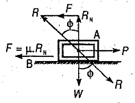
For example, a body "A" rests on a surface B. Now the force P is applied to the body.
It will not move until the force P equals the limiting friction force F.
Here, F = µ W = µ.Rn (here Rn is the normal reaction force).
No relative motion will occur if P is not equal to F. And force F will operate opposite of force P.
In the case of limiting force: it will be in equilibrium under the actions of these three forces
Body weight, W, applied force, P (horizontal) and reaction force between surfaces A and B.
Therefore, for the equilibrium condition, the reaction R will be equal to the weight W. P will be inclined at an angle ϕ with respect to the reaction force Rn. Here ϕ is called the limiting angle of friction. The mathematical relationship between angle and force is

Q6) What is Geometry of deformation?
A6) Strain and strain-displacement relations:
The shape of a solid or structure changes over time during a deformation process. To characterize the deformation or deformation, a certain reference configuration is adopted and defined as undeformed.
Often, that reference setting is chosen as a non-stressed state, but it is not necessary or always convenient.
If time is measured from zero at a time when the body exists in that reference configuration, then the capital X can be used to indicate the position vectors of the material points when t = 0.
At another time t, a point the material that was in X will have moved to a spatial position x. The deformation is described as mapping.
x = x(X, t), with x = x(X, 0) = X.
The displacement vector u is then
u = x(X, t) − X;
also, v = ∂x(X, t)/∂t
and
a = ∂2x(X, t)/∂t2.
It is easier to write equations for deformation in a way that, although approximate in general, is suitable for the case where any element of the infinitesimal line dX of the reference configuration suffers extremely small rotations and fractional variations in length, deforming into the corresponding linear element dx.
These conditions are met when | ∂ui / ∂Xj | << 1. Many solids are often sufficiently rigid, at least under the loads typically applied to them, that these conditions are realized in practice.
The linear expressions for deformation in terms of [∂u / ∂X], appropriate for this situation, are called small deformation or infinitesimal deformation.
Valid strain expressions will also be provided for rotations and fractional length variations of arbitrary size; These expressions are called finite deformation.
Two simple types of deformation are extensive deformation and shear deformation. Study a rectangular parallelepiped, a block of brick-like measurable with jointly perpendicular flat faces and let the edges of the block be parallel to axes 1, 2, and 3.
If the block is deformed homogeneously, so that each face The plane moves perpendicularly to itself and in order for the faces to remain orthogonal (i.e. the parallelepiped deforms into another rectangular parallelepiped), the block is said to have undergone extensive stress with respect to each of axes 1, 2, and 3 but without shear deformation with respect to these axes.
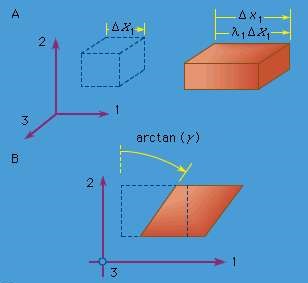
If the edge lengths of the undeformed parallelepiped are denoted as ΔX1, ΔX2, and ΔX3 and those of the deformed parallelepiped are denoted as Δx1, Δx2, and Δx3 (see Figure, where the dotted figure represents the reference configuration and line figure the deformed configuration continues), therefore the quantities λ1 = Δx1 / ΔX1, λ2 = Δx2 / ΔX2 and λ = Δx3 / ΔX3 are called stretch ratios.
There are several ways in which an extensive tension can be defined in terms of them.
Note that the change in displacement, for example, in the x1 direction between the points at one end of the block and those at the other is Δu1 = (λ1 - 1) ΔX1.
For example, if E11 indicates the extensional deformation along the x1 direction, the most commonly understood definition of deformation is
E11 = (change in length) / (initial length) = (Δx1 - ΔX1) / ΔX1 = Δu1 / ΔX1 = λ1 - 1
A variety of other extensional stress measurements can be defined by
E11 = g (λ1), where the function g (λ) satisfies g (1) = 0 and g ′ (1) = 1, to agree with what above definition when λ1 is very close 1.
Two of these commonly used measurements are the strain
EM = (λ 2/1 - 1) / 2,
based on the change in the metric tensor and the logarithmic strain
EL = ln (λ1).
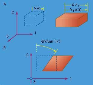
Figure: (A) Extensional strain and (B) simple shear strain, where the element drawn with dashed lines represents the reference configuration, and the element drawn with solid lines represents the deformed configuration
Q7) What is Influence Lines for Trusses?
A7)
The construction of armor lines of influence is similar to the construction of armor lines of influence; however, as mentioned earlier, it is important to determine which path the mobile load takes through the truss.
Figure shows an example of a truss for a road bridge.
In this armor, the road surface is level with the lower armor arrangement.
Therefore, an influence line for this armature would be constructed along a direct line connecting the pivot on the left with the roller on the right along the bottom chord arrangement.
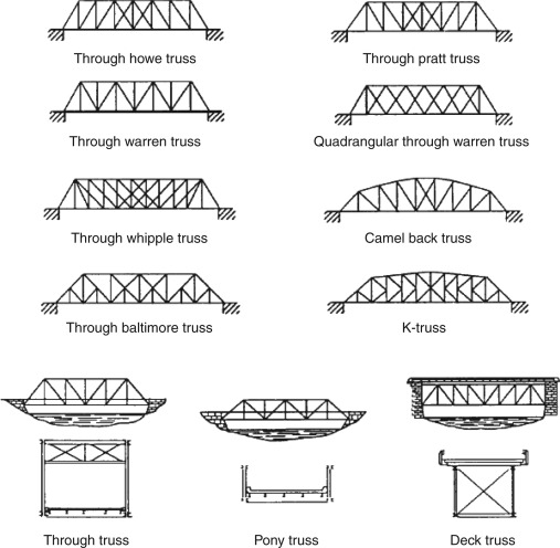
Figure: Truss Bridge Structure with Load Path
Another important difference for influence lines for trusses is that we must assume that the load can only be transferred to the truss at the intersection points between the members.
This is necessary because the truss members themselves are typically assumed to only take axial forces. Any loads between the intersection points on the truss elements would cause them to bend.
This is also how real trusses are usually designed as shown in Figure . In the figure, a typical simply-supported truss bridge is shown at the top of the figure.
Of course, for a bridge, you need to actually have two trusses, one on either side of the roadway. This is shown in the plan at the bottom of the figure, where the road deck is shown by the grey shaded area and the trusses are on either side (top and bottom).
These trusses are joined together by main beams that run between them at the locations of the intersection points between the truss members. These main beams are responsible for transmitting the load from the roadway to the truss intersection points.
The main beams are also often connected together by secondary beams. The road deck would then sit on top of the secondary beams. So, the load path for a load applied on any point of the road deck must travel through the secondary beams to the closest main beam, and from there directly to an intersection point on the truss.
The truss then transfers the main beam loads from the intersection points to the supports at either end. Sample load paths are shown in Figure .
This means that any load that is located between intersection points will be split between the two closest intersection points (in proportion to how close the load is to each intersection point).
For truss influence lines, the consequence of this is that influence lines will always consist of influence line values at intersection points, all of which are connected by straight lines.
To find these influence lines, there is no easy Müller-Breslau principle. The method of joints or method of sections must be used to find a truss member force as a function of the moving unit load position.
This also means that, like the equilibrium method for beams, you often must find the influence diagrams for one or more reaction forces before you can find the influence diagram for the internal axial force in a specific truss member.
Q8) Draw diagram of (A) Extensional strain and (B) simple shear strain?
A8)
