Unit – 1
Introduction
Q1) What is engineering drawing?
A1)
Q2) What are the types of projection?
A2)
Q3) What are the types of building drawing?
A3) Types of Building Drawing.
1. Site Plan.
2. Line Plan.
3. Detailed Plan.
4. Foundation Plan.
5. Landscape plan.
6. Elevation.
7. Sectional Elevation.
8. Perspective Drawing.
9. Submission drawing
10. Model
Q4) Define scale?
A4) Scale drawings are used to illustrate items that it is not useful or convenient to draw at their actual size
A distance at full size: The distance at the scale used that would be the same length.
For example:
In the construction industry a range of scales are available
Q5) Write advantages of CAD?
A5) 1. Saves time: It can make better and more systematic designs in shorter time duration.
2. Easy to edit: it will be much easier and safer to make any changes because you can fix the errors and modify the drawings easily.
3. Decrease in error percentage: the percentage of error that occurred because of manual designing is decreased.
4. Decrease design effort: It has been reduced significantly because the software brutalises most of the task.
5. Easy to share: It makes easier to save the files and store it in a way that you can use it time and again.
6. Improved accuracy: The fact that the kind of accuracy that CAD software will offer can never be achieved by opting for manual drawings. You have tools to measure the precision, skill and accuracy level of the designs.
Q6) What is reference plan?
A6) It is defined as a plane on the face of the extents of a modifier. Every modifier has an unseen extent, or boundary box, that defines the extents of the feature
These are the various ways of a reference plane, example of each one:
Q7) What is drawing basic entities?
A7) ENTITIES: It is the main section of a drawing file and contains the actual characteristic contains standard information, such as its colour, layer, line style, and geometry.
In a drawing you can create a variety of different entity types. Drawing entities can be very simple such as lines, circles, arcs, points and rays or complex such as polylines, splines and planes.
To create an entity, you can choose between selecting the command in the Draw menu, using the tools on the Draw
When you use a tool or a drawing command, the program box open to enter coordinate points, such as endpoints or insertion points. You can enter the points or distances either using a mouse or by typing coordinate values in the command bar
New entities are made on the current layer, using the current colour, line type and line weight.
Q8) Explain modify command?
A8) Essential Commands of Modify Panel in AutoCAD
Move (M+ Enter): -
We can move any objects at a specified distance and direction.
Process of using move command: -
Rotate (RO+ Enter): -
We can rotate any selected object around a base point to an angle.
It rotates any objects in clock and anti-clockwise.
Process of using Rotate command: -
Copy (CO+ Enter): -
It is used to copy an object at a specified distance or direction. It works almost like Move Command.
Process of using Copy command: -
Mirror (MI+ Enter): -
It creates a reverse copy of the selected object.
Process of using mirror command: -
Stretch: -
In these, one can move some part of drawing with carrying the connection with other parts.
Process of using Stretch command: -
Scale (SC+ Enter): -
We one can enlarge or reduce the objects. The length and width of objects would be enlarged or reduced at the same size.
Process of using Scale command
Q9) Define Block?
A9)
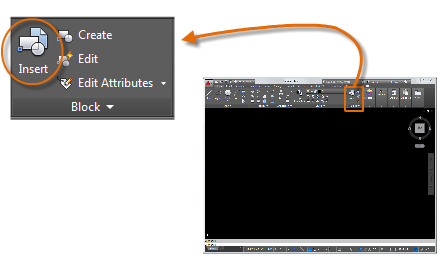
Insert a Block
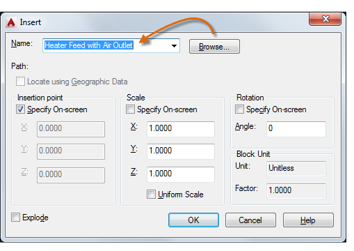
Each of these blocks is an individual drawing file, saved in a folder with similar drawing files. When you need to insert one into your current drawing file, you use the INSERT command

The first time you insert the drawing as a block, you need to click Browse to locate the drawing file.

Once inserted, the block definition is stored in your current drawing.
Q10) Explain trim command?
A10) It is used to trim any objects whose edge meet the other objects. It trims the crossed line.
Process of using Trim Command: -