Unit - 2
Friction
Q1) Two blocks A and B of weights 1 kN and 2 kN respectively are in equilibrium position as shown in Fig. If the coefficient of friction between the two blocks as well as the block B and the floor is 0.3, find the force (P) required to move the block B.
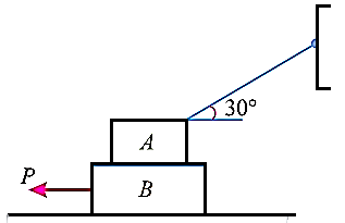
A1) Given: Weight of block A (WA) = 1 kN; Weight of block B (WB) = 2 kN and
coefficient of friction (μ) = 0.3.
Forces acting on blocks A and B are plotted respectively as,
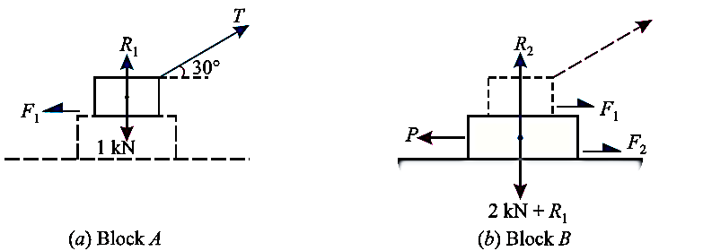
The forces acting on the two blocks A and B are shown in fig. 8.5(a) and (b) respectively .
First of all, consider the forms acting in block A
Resolve the forces vertically


And now resolving the forces horizontally

Diving equation 1 by 2


Now considered the block B. A little consideration will show that the downward force of the block A (equal to R) will also act along with the weight of the block B
Resolving the forces vertically


And now resolving the forces horizontally

Q2) What is the maximum load (W) which a force P equal to 5 kN will hold up, if the coefficient of friction at C is 0.2 in the arrangement shown in Fig. Neglect other friction and weight of the member. If W = 3 kN and P = 4.5 kN, what are the normal and tangential forces transmitted at C?
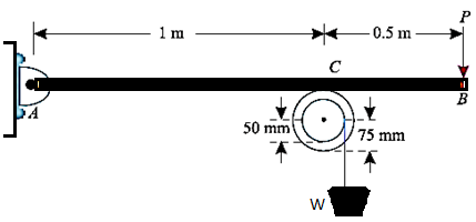
A2) Given force (p)=5KN nad coeffecient of friction at 
Maximus load W
Let,
R= normal reaction of the pulley on the beam at C
First of all, consider the equilibrium of the beam AB. Taking moments about the hinge A and equation the same
R*1=5*1.5=7.5
Now consider the equilibrium of the pulley. it is subjected to a normal reaction of 7.5 KN (as calculated above) tends to rotate it. A little consideration will show that the rotation of the pulley is prevented by the frictional force between the pulley and beam at C. we know that maximum force of friction at C.

Now taking moment about the center of the pulley and equating the same


Normal and tangential force transmitted at C
Now considered a weight W equal to3KN suspended from the pulley and a force P equal to 4.5KN applied at B
Let ,


Again considered equilibrium of the beam taking moment about the hinge A and equating the same.


We know that the tangential force at C will be the frictional force at C will be the frictional force between the pulley and beam . Again taking the moment about the center of the pulley and equation the same


Q3) A body of weight 500 N is lying on a rough plane inclined at an angle of 25° with the horizontal. It is supported by an effort (P) parallel to the plane as shown in Fig. Determine the minimum and maximum values of P, for which the equilibrium can exist, if the angle of friction is 20°.
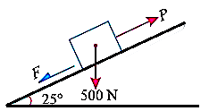
A3) Given weight of the body (W)=500N Angle at which plane is inclined 
Maximum value of P
We know that for the minimum value of P, the body is the point of sliding downward. we also know that the body is the point of sliding downward then the force.


Q4) An inclined plane as shown in Fig. below. is used to unload slowly a body weighing 400 N from a truck 1.2 m high into the ground. The coefficient of friction between the underside of the body and the plank is 0.3. State whether it is necessary to push the body down the plane or hold it back from sliding down. What minimum force is required parallel to the plane for this purpose?
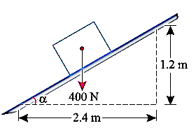
A4) Given weight of body (W)=400N and coeffecient of friction 
Whether it is necessary to push the body down the plane or hold it back from sliding down
We know that


=400*0.894=357.9N
Force of friction

Now resolving the 400N force along the plane


We know that the force along the plane (which is responsible for sliding the body) is more than the force of friction, therefore the body will slide down. or in other words, it is not necessary to push the body down the plan e, rather it is necessary to hold it back from sliding down
Minimum force required parallel to plane
We know that the minimum force required parallel to plane to hold the body back
P=178.5-107.3=71.2 N Ans
Q5) It is observed that when the bed of the dump truck is raised to an angle of the vending machines will begin to slide off the bed, Fig. shown. Determine the static coefficient of friction between a vending machine and the surface of the truck bed.
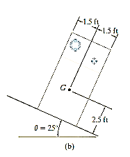
A5) The free body diagram of the component will be as,
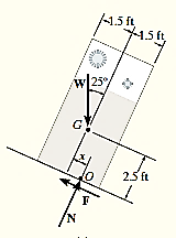
Equation in equilibrium


Since slipping impends at is referred to as the angle of repose and by comparison , it is equal to the angle of static friction
  notice from the calculation that
  is independent of the weight of the vending machine and so knowing
  provides a convenient method for determining the coeffecient of static friction .
Q6) The uniform 10-kg ladder in Fig. rests against the smooth wall at B, and the end A rests on the rough horizontal plane for which the coefficient of static friction is 0.3. Determine the angle of inclination of the ladder and the normal reaction at B if the ladder is on the verge of slipping.
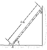
A6) Free-Body Diagram. As shown on the free-body diagram, Fig. below, the frictional force must act to the right since impending motion at A is to the left.
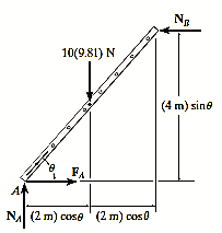
Equation of equilibrium and friction =
Since the ladder is on the verge of slipping then  . By inspection
  can be obtained directly.

Using the result  . now
. now  can be found


Finally, the angle  can be determined by summing moments about point A


Q7) Beam AB is subjected to a uniform load of 200N/m and is supported at B by post BC, Fig. below. If the coefficients of static friction at B and C are 0.2 and 0.5, determine the force P needed to pull the post out from under the beam. Neglect the weight of the members and the thickness of the beam.
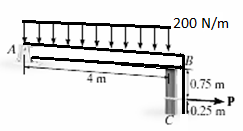
A7) Free body diagram: The free body diagram is drawn as shown below.
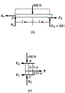
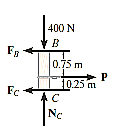
Equation and equilibrium and friction


Post slips at B and rotates about C. This required 

Using this result and solving Eqs.1 through 3, we obtain
P= 320N


Since  >
> , slipping at C occurs. Thus, the other case of movement must be investigated
(Post slips at C and rotates about B). here 

Solving eqs. 1 through 4 yields.


Q8) The turnbuckle shown in Fig. below has a square thread with a mean radius of 5 mm and a lead of 2 mm. If the coefficient of static friction between the screw and the turnbuckle is 0.25, determine the moment M that must be applied to draw the end screws closer together.
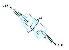
A8) The moment can be obtained by applying Eq. 8-3 since friction at two screws must be overcome, this requires

Here
W=2000N
r=5mm


Substituting these values intoEq.1 and solving gives

6374.7Nmm=6. 37N.m
Q9) Determine the required force P in Fig. 11–7a, needed to maintain equilibrium of the scissor’s linkage when 600. The spring is unstretched when 300 . Neglect the mass of the links.
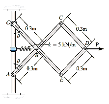
A9) Free body is drawn as follows:
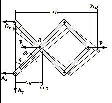
Virtual displacment :- The position coordinates , measured from the fixed point A, are used to locate
  . These coordinates are parallel to the lines of action of their corresponding forces. Expressing
  in terms of the angle
  using trignometry,


Differentiating , we obtain the virtual displacment of point B and D


Virtual work equation- force P does positive work since it acts in the positive sense of its virtual displacment . The spring force  does negativity work since it acts opposite to its positivity virtual displacement . thus , the virtual -work equation becomes


Since 

When 

Q10) If the box in Fig. below has a mass of 10 kg, determine the couple moment M needed to maintain equilibrium when. Neglect the mass of the members.
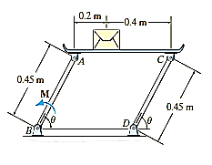
A10) Initially, free body diagram is drawn as
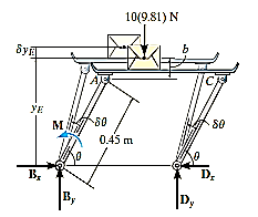
Virtual Displacements: - The position coordinate  , measured from the fixed-point B, locates the weight, 10(9.81) N. Here,

Where b is a constant distance. Differentiating this equation, we obtain

Virtual-Work Equation: - The virtual-work equation becomes

Substituting Eq.1 into this equation


Since  , then

Since it is required that  then
then

Q11) The mechanism in Fig. below supports the 50-lb cylinder. Determine the angle for equilibrium if the spring has an unstretched length of 2 ft when angle is 0. Neglect the mass of the members.
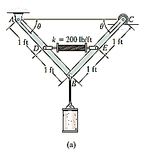
A11) The free body diagram is as shown in fig. below.
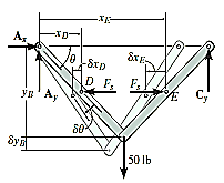
Virtual Displacements. The position coordinates  are established from the fixed-point A to locate
  at D and at E. The coordinate
  , also measured from a, specifies the position of the 50-lb force at B. The coordinates can be expressed in terms of
  using trigonometry.


Differentiating we obtain the virtual displacements of points D, E, and B as


Virtual-Work Equation. The virtual-work equation is written as if all virtual displacements are positive, thus


Since  then
then

Solving by trial and error,
