Unit - 3
Basic Structural Analysis
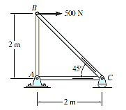
Q1) Determine the force in each member of the truss shown in Fig. and indicate whether the members are in tension or compression.
Solution:
Joint B. The free-body diagram of the joint at B is shown in Fig. 6-8b. applying the equations of equilibrium we have


Since the force in member BC has been calculated, we can proceed to analyse joint C to determine the force in member CA and the support reaction at the rocker.
Joint C. From the free -body diagram of joint C. Fig 6-8c, we have


Joint A. although it is not necessary, we can determine the component of the support reaction at joint A using the results of  and
and  . from the free – body diagram fig 6-8d, we have


Note. The results of the analysis are summarized in Fig. 6-8e. Note that the free-body diagram of each joint (or pin) shows the effects of all connected members and external forces applied to the joint. Whereas the free-body diagram of each member shows only the effects of the end joints on the member.
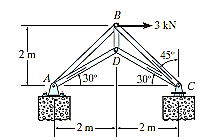
Q2) Determine the forces acting in all the members of the truss shown in Fig.
A2)


These two equations must be solved simultaneously for each of the two unknowns. Note, however, that a direct solution for one of the unknown forces may be obtained by applying a force summation along an axis that is perpendicular to the direction of the other unknown force. For example, summing forces along the y’ axis, which is perpendicular to the direction of  , Fig. 6-9d, yields a direct solution for
  .
.


Joint D. We can now proceed to analyse joint D. The free-body diagram is shown in Fig. 6-9e


Note: The force in the last member, BA can be obtained from joint B or joint A. As an exercise, draw the free-body diagram of joint B, sum the forces in the horizontal direction, and show that 
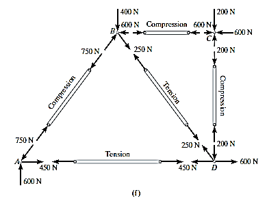
Q3) Determine the force in each member of the truss shown in Fig. Indicate whether the members are in tension or compression.
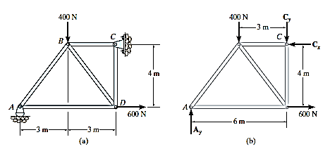
A3) Support Reactions. No joint can be analysed until the support reactions are determined, because each joint has at least three unknown forces acting on it. A free-body diagram of the entire truss is given in Fig. 6-10b. Applying the equations of equilibrium, we have


The analysis can now start at either joint A or C. The choice is arbitrary since there are one known and two unknown member forces acting on the pin at each of these joints.
Joint A. As shown on the free-body diagram,  is assumed to be compressive and
  is tensile. Applying the equations of equilibrium, we have


Joint D Using the result for  and summing forces in the horizontal direction, Fig 6-10d, we have

The negative sign indicates that  acts in the opposite sense to that shown in Fig 6-10d. Hence,

To determine  , we can either correct the sense of
  on the free-body diagram, and then apply
  , or apply this equation and retain the negative sign for
  i.e.
i.e.

Joint C.


Note: The analysis is summarized in Fig.6-10f, which shows the free body diagram for each joint and member.
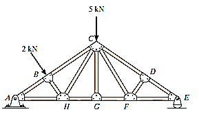
Q4) Using the method of joints, determine all the zero-force members of the Fink roof truss shown in Fig. Assume all joints are pin connected.
A4)
Look for joint geometries that have three members for which two are collinear We have
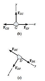
Joint G.

Realize that we could not conclude that GC is a zero-force member by considering joint C, where there are five unknowns. The fact that GC is a zero-force member means that the 5-kN load at C must be supported by members CB, CH, CF and CD.
Joint D.

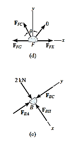
Joint F.

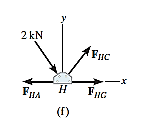
Note: If joint B is analysed, Fig. 6-13e

Also,  must satisfy
  , Fig. 6-13f, and therefore HC is not a zero-force member.
Q5) Determine the force in members GE, GC, and BC of the truss shown in Fig. Indicate whether the members are in tension or compression.
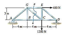
A5)
Applying the conditions of equilibrium here,


Free Body Diagram: - For the analysis the free-body diagram of the left portion of the sectioned truss will be used, since it involves the least number of forces, Fig. 6-16c
Equations of Equilibrium: Summing moments about point G eliminates  and yields a direct solution for
  .
.


In the same manner by summing moments about point C we obtain a direct solution for 


Since  and
and  have no vertical components, summing forces in the y direction directly yields
  , i.e.


Q6) Determine the force in member CF of the truss shown in Fig. Indicate whether the member is in tension or compression. Assume each member is pin connected.

A6) Free Body Diagram
Section aa in Fig 6-17a will be used since this section will expose the internal force in member CF as external on the free-body diagram of either the right or left portion of the truss. It is first necessary, however, to determine the support reactions on either the left or right side. Verify the results shown on the free-body diagram in Fig 6-17b.
The free body diagram of the right portion of the truss, which is the easiest to analyse is shown in Fig 6-17c There are three unknowns, 
Equations of equilibrium. We will apply the moment equation about point O in order to eliminate the two unknowns  the location of point O measured from E can be determined from proportional triangles i.e., 4/(4+X) =6/(8+X), X =4m. Or, stated in another manner the slope of member GF has a drop of 2m to a horizontal distance of 4m. Since FD is 4m, Fig. 6-17c, then from D to O the distance must be 8m.
An easy way to determine the moment of  about point O transmissibility and slide
  to point C, and then resolve
  into its two rectangular components. We have


Q7) Draw the free-body diagrams of the members of the backhoe, shown in the photo, Fig. below. The bucket and its contents have a weight W.
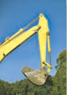
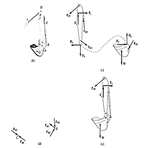
A7) The idealized model of the assembly is shown in figure 6-24b. By inspection, members AB, BC, BE and HI are all to force members since they are pin connected at their and points and no other forces act on them. The free body diagrams of the bucket and the stick as shown in figure 6-24c. Note that pin C is subjected to only two forces, whereas the pin at B ages subjected to three forces, Fig 6-24d. The free body diagram of the entire assembly is shown in figure 6-24e.

Q8) Determine the tension in the cables and also the force P required to support the 600-N force using the frictionless pulley system shown in Fig a.
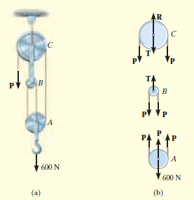
A8) Free body diagram. A free body diagram of each pulley including its pain and a portion of the contacting cable is shown in figure 6-26b. Change the cable is continuous, it has a constant tension P acting throughout its length. The link connection between pulleys B and C is a two-force member, and therefore it has an unknown tension T acting on it. Notice that the principle of action, equal but opposite reaction must be carefully observed for forces P and T when the separate free body diagrams are drawn.
Equations of equilibrium. The three unknowns are obtained as follows:
Pulley A

Pulley B

Pulley C

Q9) A 500-kg elevator car in Fig. a. is being hoisted by motor A using the pulley system shown. If the car is traveling with a constant speed, determine the force developed in the two cables. Neglect the mass of the cable and pulleys.
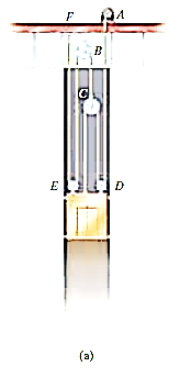
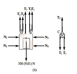
A9) Free body diagram. We can solve this problem using the free body diagrams of the elevator car and pulley C, Fig 6-27b, the tensile forces developed in the cables are denoted as 
Equations of Equilibrium. For pulley C,

For the elevator car,

Substituting Eq. (1) into Eq. (2) yields


Substituting this result into Eq. 1

Q10) The compound beam shown in Fig. A is pin connected at B. Determine the components of reaction at its supports. Neglect its weight and thickness.

A10) Free body diagrams.
By inspection if we consider a free body diagram of the entire beam ABC, there will be three unknown reactions at A and one at C. These four unknowns cannot all be obtained from the three available equations of equilibrium. And so, for the solution it will become necessary to dismember the beam into its two segments, as shown in Fig. 6-29b
Equations of equilibrium. The six unknowns are determined as follows
Segment BC


Segment AB


Solving each of these equations successively, using previously calculated results, we obtain


 Q11) The two planks in Fig. (a) are connected together by cable BC and a smooth spacer DE. Determine the reactions at the smooth supports A and F, and also find the force developed in the cable and spacer.
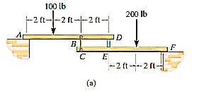
A11) Free-Body Diagrams: The free body diagram of each plank is shown in Fig. 6-30b. It is important to apply Newton’s third law to the interaction forces  as shown
Equations of Equilibrium For plank AD,


Solving simultaneously,

Using these results, for plank AD,


Note: Draw the free-body diagram of the system of both planks and apply  to determine
  .Then use the free-body diagram of CEF to determine
  .
.
Q12) A hydraulic-lift table is used to raise a 1000-kg crate. The table consists of a platform and two identical linkages on which hydraulic cylinders exert equal forces. (Only one linkage and one cylinder are shown.) Members EDB and CG are each of length 2a, and member AD is pinned to the midpoint of EDB. If the crate is placed on the table so that half of its weight is supported by the system shown, determine the force exerted by each cylinder in raising the crate for θ = 60°, a = 0.70 m, and L = 3.20 m. Show that the result is independent of the distance d.
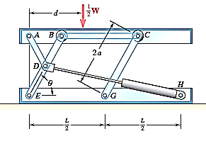
A12) Strategy: the free body diagram of the platform and linkage system will involve more than three unknowns so it alone cannot be used to solve this problem. Instead, and work from them.
Modelling: - the machine consists of the platform and the linkage. It's free body diagram includes an input force  exerted by the cylinder; the weight W/2, which is equal and opposite to the output force; and reactions at E and G, which are assumed to be directed as shown. Dismember the mechanism and draw a free body diagram for each of its component parts. Note that AD, BC and CG are two force members. Member CG has already been assumed to be in compression; now as you mean that AD and BC are in tension and direct the forces exerted on them as shown. Use equal and opposite vectors to represent the forces exerted by the two force members on the platform, on member BDE, and on roller C
Analysis
Free Body Platform ABC


Free Body Roller C Draw a force triangle and obtain

Free Body Member BDE Recalling that 


From Equation (1) you obtain

Note that the result obtained is independent of d.
Applying first law of sines to triangle EDH you have

Now using the law of cosines, you get


Also note that
W=mg=1000kg (9.81m/s^2) =9810N=9.81kN
Substituting for  from Eq (3) into Eq (2) and using the4 numerical data, your result is


Q13) Draw a free-body diagram with the coordinate axes shown (Fig. 1) and express the unknown cable tension as a Cartesian vector. Then apply the equilibrium equations to determine this tension and the support reactions.
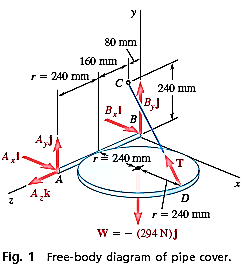
A13) Modelling;
Free body diagram. The forces acting on the free body include its weight, which is
W=-mgj=-(30Kg) (9.81
The reactions involved six unknowns: the magnitude of the force T exerted by the cable, three force components at hinge B. Express the components of T in terms of the unknown magnitude T by resolving the vector  into rectangular components.


Equilibrium Equations: - The forces acting on the pipe cover form a system equivalent to zero. Thus,


Setting the coefficients of the unit vectors equal to zero in Eq. (2) gives three scalar equations, which yield

Setting the coefficients of the unit vectors equal to zero in Eq. (1) produces three more scalar equations. After substituting the values of T,  into these equations you obtain

The reactions at A and B are therefore
A=+(49.0N) i+73.5N) j+(98.0) Nk
B=+245N) i+(73.5N) j
Reflect and think: As a check, you can determine the tension in the cable using a scalar analysis. Assigning signs by the right-hand rule we have
(+rhr) 