Unit-6
Rock masses as construction material
Q1) Explain rock masses as construction materials.
A1) Rock masses as construction materials
A rock mass is a material quite different from other structural materials used in civil engineering. It is heterogeneous and quite often discontinuous, but is one of the materials in the earth's crust, which is mostly used in man's construction. Ideally, a rock mass is composed of a system of rock blocks and fragments separated by discontinuities forming a material in which all elements behave in mutual dependence as a unit. The material is characterized by the shape and dimensions of rock blocks and fragments, by their mutual arrangement within the rock mass, as well as by joint characteristics such as joint wall conditions and possible filling (Fig. 6.1).

Fig. The main features constituting a rock mass
The complicated structure of the rock mass with its defects and inhomogeneities and the wide range of its applications cause challenges and problems in rock engineering and construction which often involve considerations that are of relatively little or no concern in most other branches of engineering. One of these challenges isthe uncertainties about geological conditions and geotechnical parameters. This is perhaps one of the most distinctive features of engineering geology compared to other engineering fields, therefore 'engineering judgment', adaptable design approaches, and other procedures for dealing with uncertainty or hedging against it have been taken into use.
Important in all rock mechanics, rock engineering, and design are the quality of the geo-data that form the basis for the calculations and estimates made. This quality depends on two main features.
1. The understanding and interpretation of the geological setting of the area of interest.
2. The way the (known) rock mass at the site is described or measured.
The first feature is important mainly in the pre-construction phase and is a result of the geological understanding based on field investigations and the experienced interpretation of available results. To a great extent, this is often wholly dependent on the skill of the geologist(s) who decide how the investigations should be done and how the geo-data should be combined. Thus, this process can in many instances be said to be more an "art" than a science.
The second feature is mainly connected to the present work. Brown (1986) thinks that "inadequacies in site characterization of geo-data probably present the major impediment to the design, construction, and operation of excavations in rock. Improvements in site characterization methodology and techniques and the interpretation of the data are of primary research requirements, not only for large rock caverns but for all forms of rock engineering."
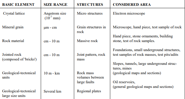
Table: Basic elements and relevant considered areas
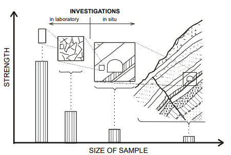
Fig. The scale factor of rock masses and the variation in the strength of the material depending on the size of the 'sample' involved.
Other special features in a rock mass and its utilization in contrast to other construction materials are:
- the size or volume of the material involved, see Fig 6.2 and Table 6.1,
- the structure and composition of the material,
- the many constructions and utilization purposes of it, see Table 6.2, and
- the difficulties in measuring the quality of the material.
Q2) What do you mean by rocks and explain their main features in details.
A2) Rocks and their main features
Geologists use a classification, which reflects the origin, formation, and history of a rock rather than its potential mechanical performance. The rock names are defined and used not as a result of the strength properties, but according to the abundance, texture, and types of the minerals involved, in addition to the mode of formation, degree of metamorphism, etc. According to Franklin (1970), there are over 2000 names available for the igneous rocks that comprise about 25% of the earth's crust, in contrast to the greater abundance of mud rocks (35%) for which only a handful of terms exist; yet the mud rocks show a much wider variation in mechanical behaviour.
Fresh rocks
Each particular rock type is characterized by its minerals, texture fabric, bonding strength, and macro and microstructure, see Fig. 6.3.
Igneous rocks tend to be massive rocks of generally high strength. Their minerals are of a dense interfingering nature resulting in only slight, if any, directional differences in mechanical properties of the rock. These rocks constitute few problems in rock construction when fresh.
Sedimentary rocks constitute the greatest variation in strength and behaviour. The minerals of these rocks are usually softer and their assemblage is generally weaker than the igneous rocks. In these rocks, the minerals are not interlocking but are cemented together with an inter-granular matrix material. Sedimentary rocks usually contain bedding and lamination or other sedimentation structures and, therefore, may exhibit significant anisotropy in physical properties depending upon the degree of their development. Of this group, argillaceous and arenaceous rocks are usually the most strongly anisotropic. Some of the rocks are not stable in the long term, for example, mud rocks, which are susceptible to slaking and swelling. This group of rocks, therefore, creates many problems and challenges in rock construction.
Metamorphic rocks show a great variety in structure and composition and properties. The metamorphism has often resulted in hard minerals and high intact rock strength; however, the preferred orientation of platy (sheet) minerals due to shearing movements results in considerable directional differences in mechanical properties. Particularly the micaceous and chloritic schists are generally the most outstanding for anisotropy.
The influence from some minerals
Certain elastic and anisotropic minerals like mica, chlorite, amphiboles, and pyroxenes may highly influence the mechanical properties of the rocks in which they occur. The parallel orientation of these minerals is often found in sedimentary and regional metamorphic rocks in which weakness planes may occur along with layers of these flaky minerals. Where mica and chlorite occur in continuous layers their effect on rock behaviour is strongly increased. Thus, mica schists and often phyllites have strong anisotropic mechanical properties of great importance in rock construction. Also, other sheet minerals like serpentine, talc, and graphite reduce the strength of rocks due to easy sliding along the cleavage surfaces, see Fig. 6.3.
Quartz is another important mineral in rock construction. This mineral is grade 7 on the Mohs scale of hardness. Sharp, obtuse-angled edges of the quartz grains have an unfavourable shape regarding drill bit and cutter wear in percussion drilling and TBM boring respectively, while the effect from rounded quartz grains is significantly less.
Change of moisture content in swelling minerals of the smectite (montmorillonite) group can cause significant problems related to high swelling pressures. These minerals, occurring either as infilling or alteration products in seams or faults, have in addition to the expansion, a low shear strength, which may contribute to rockfalls and, in some cases, slides in underground openings and cuttings. Also, some rocks may show swelling properties. These rocks can be montmorillonite shales, altered or weathered basalts, in addition to other igneous, metamorphic rocks, or sedimentary rocks containing anhydrite.
Some rocks may slake (hydrate or "swell", oxidize), disintegrate, or otherwise weather in response to the change in humidity and temperature consequent on excavation. As mentioned above, an abundant group of rocks, the mudrocks, are particularly susceptible to even moderate weathering.
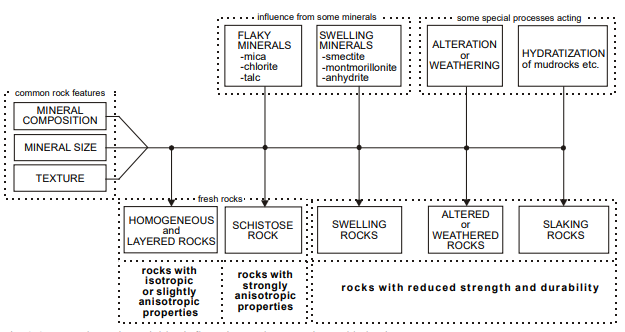
Fig. The main variables influencing rock properties and behaviour
Q3) Explain effect of alteration and weathering in detail.
A3)
The processes of alteration and weathering with the deterioration of the rock material have a reducing effect on the strength and deformation properties of rocks, and may completely change the mechanical properties and behavior of rocks (refer to Fig. 6.3). For most rocks, except for the weaker types, these processes are likely to have a great influence on the engineering behavior of rock masses. Hence, the description and characterization of rock masses should pay particular attention to such features. Rocks are frequently weathered near the surface and are sometimes altered by hydrothermal processes. Both processes generally first affect the walls of the discontinuities. The main results of rock weathering and alteration are:
Mechanical disintegration or breakdown, by which the rock loses its coherence, but has little effect upon the change in the composition of the rock material. The results of this process are:
- The opening up of joints.
- The formation of new joints by rock fracture, the opening up of grain boundaries.
- The fracture or cleavage of individual mineral grains.
Chemical decomposition, which involves rock decay accompanied by marked changes in chemical and mineralogical composition results in
- Discoloration of the rock.
- Decomposition of complex silicate minerals (feldspar, amphibole, pyroxene, etc) eventually producing clay minerals; some minerals, notably quartz, resist this action and may 'survive' unchanged.
- Leaching or solution of calcite, anhydrite, and salt minerals.
The disintegration leads mainly to a greater number of joints in rock masses located in the upper zone of weathering, while decomposition influences the joint condition as well as the rock material.
Rocks that differ in mineral composition, porosity, cementation, consolidation, texture, and structural anisotropy can be expected to have different strength and deformation properties. The geological nomenclature of rocks emphasizes mainly solid constituents, whereas, from the engineer's point of view, pores, defects, and anisotropy are of greater mechanical significance. For each type of rock, the mechanical properties vary within the same rock name. Petrological data can, however, make an important contribution towards the prediction of mechanical performance, provided that one looks beyond the rock names to the observations on which they are based. It is, therefore, important to retain the names for the different rock types, for these in themselves give relative indications of their inherent properties.
Q4) What are the main features that affect the quality of rock engineering and design?
A4) Main features that affect the quality of rock engineering and design
Rock is a heterogeneous and composite geomaterial and its strength under triaxial compressive stresses 1s a function of some internal and external factors. External factors are controllable but internal factors are related to the heterogeneous nature of rock and they are out of control. The estimation of the real value of the strength of even one type of rock, due to the inherent characteristics, is a complex subject. That is because if one factor varies other variables control the mechanical behavior.
Porosity and density are two inherent variables in the complex nature of the rock. The difference in the strength of rock is largely dependent upon the value of porosity. The determination of the effects of porosity and density on the strength of rock under triaxial compressive stresses has not been possible due to the heterogeneous nature of the rock. Also if one factor such as porosity varies other variables are affected. Various failure criteria for intact rock were proposed in the last decades. The parameters of failure criteria in terms of important factors such as porosity that greatly affect the strength have not yet been developed. The forms of failure criteria of rock masses have originally been derived from those proposed for intact rock and the parameters need to be determined. Theme chanical behaviors and the values of parameters of failure criteria for one type of rock can be a function of the porosity which has a major effect on the strength. Development of a method to identify the effects of porosity and density on the strength and the detailed determination of the mechanical behavior of rock under triaxial compressive stresses give fundamental information in rock mechanics.
Very little attention has been paid to the effect of some factors such as diameter to-height ratio and boundary condition on the strength of rock under triaxial compressive stresses. The effect of confining pressure on the axial compressive strength of specimens having different diameter-to-height ratios is similar to the effect of rib support on the compressive strength of pillars or the effect of confinement due to the bolts on the compressive strength of the bolted pillars. Triaxial test results from rock specimens tested in the laboratory are commonly used in rock mechanics design but the effects of diameter-to-height ratio and boundary condition on the strength in triaxial tests have not been considered. Therefore, investigations into the effects of diameter to-height ratio and boundary condition on the strength in triaxial tests play an important role in rock mechanics. Over-estimation and under-estimation strength of rock have important roles in the safety and economics of geomechanically projects.
For some engineering or rock mechanics purposes the mechanical characterization of rock material alone can be used, namely for drill ability, crushability, aggregates for concrete, asphalt, etc. Also, in assessment for the use of full-face boring machines (TBM), rock properties like compressive strength, hardness, anisotropy are among the more important parameters.
The following parameters are most frequently applied in design and classification systems:
- the rock material (rock type, geological name, weathering and alteration, strength);
- the degree of jointing (joint spacing, block size, RQD); and
- in situ stresses.
Also such features as:
- orientation of main discontinuities or joint set;
- joint conditions;
- block shape or jointing pattern;
- faults and weakness zones; and
- excavation features (dimension, orientation, etc.) have been considered as important parameters in rock masses
Q5) Explain basic element and structures of rock those are relevant in civil engineering areas.
A5) Basic element and structures of rock those are relevant in civil engineering areas
Any structural or geological feature that changes or alters the homogeneity of a rock mass can be considered a discontinuity. Discontinuities constitute a tremendous range, from structures which are sometimes thousands of meters in extent down to - per definition - mm size, see Fig. 6.4
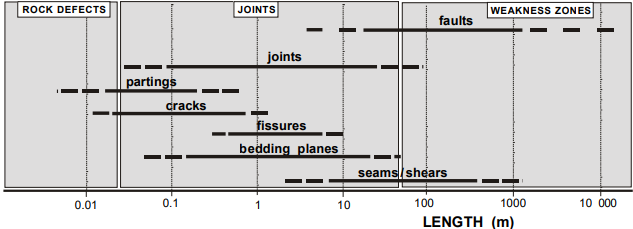
Fig. The main types of discontinuities according to size.
The different types, such as faults, dykes, bedding planes, tension cracks, etc. have completely different engineering significance. The roughness, nature of their contacts, degree, and nature of weathering, type and amount of gouge, and susceptibility to groundwater flow will vary greatly from one type of discontinuity to another since their cause, age, and history of development are fundamentally different. The effect on rock masses due to these localized discontinuities varies considerably over any given region depending on structure, composition, and type of discontinuity.
The great influence of discontinuities upon rock mass behavior calls for special attention to these features when characterizing rock masses for practical applications. Joints and faults have numerous variations in the earth's crust, this is probably the main reason that it has been so difficult to carry out common observation and description methods.
Faults
Faults are breaks along which there has been a displacement of the sides relative to one another parallel to the break. Minor faults range in thickness from decimetre to meter; major faults from several meters to, occasionally, hundreds of meters. It is important to realize that most fault zones are the result of numerous ruptures throughout geological time and that they quite often are associated with other parallel discontinuities that decrease in frequency and size in the direction away from the central zone.
Faults and fault zones often form characteristic patterns in the earth's crust consisting of several independent sets or systems, see Fig 6.5. The main directions, which mainly were determined by the state of stress, have often the same orientations as the joint sets within the same structural area.
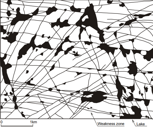
Fig. Patterns in weakness zone
Hydrothermal activity and other processes may have caused alteration of minerals into clays, often with swelling properties. Many faults and weakness zones thus contain materials quite different from the 'host' rock. The problems related to weakness zones may, therefore, depend on several factors which may all interplay in the final behavior.
Weakness zones and faults show numerous variations in their structures and compositions, see Fig 6.6. In cases where the zones or faults are composed mainly of joints and seams, they may be characterized by the same descriptions as for jointing. In other cases, it may be necessary to characterize them by special descriptions and measurements or tests. The fact that faults and weakness zones of significant size can have a major impact upon the stability as well as on the excavation process of an underground opening necessitates that special attention, follow-up, and investigations often are necessary to predict and avoid such events.
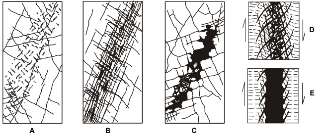 Fig. Sketches of some types of weakness zones.
Q6) Explain in brief joint and their main features.
A6) Joints and their main features
Joints are the most commonly developed of all structures in the earth's crust since they are found in all competent rocks exposed at the surface. Yet, although they are so common and have been studied widely, they are perhaps the most difficult of all structures to analyze. The analytical difficulty is caused by the number of fundamental characteristics of these structures. There is, however, abundant field evidence that demonstrates that joints may develop at practically all ages in the history of rocks.
A joint can be open or closed. Closed joints may be nearly invisible. Yet they constitute surfaces along which there is no resistance against separation. In quarries, the spacing of joints determines the largest size of blocks of sound rock which can be obtained. Therefore, joints and joint systems have attracted the attention of builders ever since cut stones have been used.
A joint is composed of several characteristics. In addition to the length and continuity of the joint, the main are:
- roughness and strength of the joint wall surface,
- waviness or planarity of the joint wall,
- alteration or coating of the joint wall, and
- possible filling. Refer to Fig. 6.7.
All these parameters influence the shear strength of the joint. They also determine the amount of water that can flow through the joint. condition of the joint wall surface.
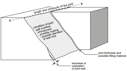
Fig. Sketch showing the main features of a joint.
The distance between the two matching joint walls controls the extent to which these can interlock. In the absence of interlocking, the properties of the filling of the joint determine the shear strength of the joint. As separation decreases, the asperities of the rock wall gradually become more interlocked, and the rock wall properties are the main contributor to the shear strength.
Q7) Explain main jointing characteristics in detail.
A7) The main jointing characteristics
By jointing is meant the pattern and frequency or density of joints. Field studies of several workers have shown that the joints preferentially are found in certain directions. One to three prominent sets and one or more minor sets may occur; also, several individual or random joints are often present.
The joints delineate blocks. Their dimensions and shapes are determined by the joint spacings, by the number of joint sets, and by random joints. Several authors state that block size is an extremely important parameter in rock mass behavior. Several scale effects in rock engineering can be explained by this feature including compressive strength, deformation modulus, shear strength, etc.
Different methods are used for measuring the jointing density. The most common are:
- Joint spacing, either in surfaces or in drill cores or scan lines.
- Density of joints, either in surfaces or in boreholes or scan lines.
- Block size, in surfaces, and
- Rock quality designation (RQD), in drill cores.
The rock mass
Discontinuities ranging in lengths from less than a decimeter to several kilometers divide the bedrocks into units, volumes, or blocks of different scales (Fig. 6.8):
Based on this it has been found useful for engineering geological and design purposes to divide the ground into:
- "The detailed jointing" formed mainly by the third and fourth-order blocks or units, and
- "The coarse pattern of weakness zones" formed by the first order blocks or units by faults and weakness zones.
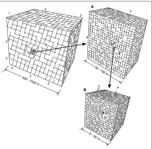
Fig. Simplified model of various dimensions units or blocks formed by discontinuities of different size
The rock blocks in the detailed jointing pattern including the rock fragments or pieces caused by the small joints/fissures are the main feature in the rock mass characterization developed herein.
Q8) Explain main types of works connected to rock and rock masses and explain important variables influencing rock properties.
A8)
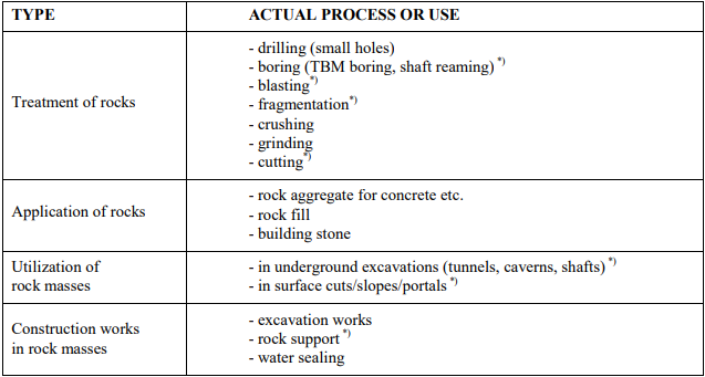
Table: Main types of works connected to rocks and rock masses
These factors imply that other methods of data acquisition are used and that other procedures in the use of these data for construction purposes have been developed. Thus, the material properties of rock masses are not measured but estimated from descriptions and indirect tests. The stress is not applied by the engineering but is already present; the construction, however, leads to stress changes.
Texture influences the rock strength directly through the degree of interlocking of the component grains.
Rock defects such as microfractures, grain boundaries, mineral cleavages, and planar discontinuities influence the ultimate rock strength and may act as “surfaces of weakness” where failure occurs.
When cleavage has high or low angles with the principal stress direction, the mode of failure is mainly influenced by the cleavage.
Anisotropy is common because of preferred orientations of minerals and directional stress history.
Rocks are seldom continuous owing to pores and fissures (i.e. Sedimentary rocks).
Temperature and Pressure
All rock types undergo a decrease in strength with increasing temperature and an increase in strength with increasing confining pressure. At high confining pressures, rocks are more difficult to fracture.
Pore Solutions
The presence of moisture in rocks adversely affects their engineering strength. Reduction in strength with increasing H2O content is due to lowering of the tensile strength, which is a function of the molecular cohesive strength of the material.
Seismic velocity
Seismic velocity is the velocity of propagation of pressure waves through a rock mass. Seismic velocity is a function of many rock material properties, including density, porosity, mineral composition, and the degree of cementation and consolidation; and rock mass properties, including the degree of fracturing and degree of weathering. Different seismic velocities are also obtained for wet and dry joint apertures in rock masses that are otherwise identical.
Weathering
Weathering is the physical disintegration or chemical decomposition of earth materials resulting in changes in the color, texture, composition, density, or form, with little or no transport of the loosened or altered material. In this section, the scope of weathering is limited to the condition of the joint face rock material. The effects of weathering tend to diminish with depth and are best assessed on a macroscopic scale in the field. The rate and type of rock weathering depend on climate, topography, vegetation, time, and the physical and chemical composition of the rock.
Physical weathering is the disintegration of rock into essentially unaltered pieces by the following processes:
All chemical weathering reactions use water as either a reactant or the carrier of reactant products. The chief chemical weathering processes are hydration, hydrolysis, oxidation, carbonation, and solution.
Q9) What are the various terminology used in weathering?
A9) Secondary cavities
Secondary cavities are open holes and voids, such as pits, vugs, and vesicles, that form as a result of chemical or mechanical processes acting on the rock mass after its formation. These types of secondary cavities are exclusive of fractures, jointing, and other open, planar, secondary features.
Fresh rock can be described as a rock that is not affected by weathering. It is also known as unweathered rock. It cannot be broken easily by hammer; makes a ringing sound when struck by hammer; it shows no visible signs of decomposition (i.e. no discoloration). It may show slight discoloration along discontinuities sometimes.
Effect of alteration and weathering
Weathering and alteration produce changes in the mineralogical composition of a rock that results in the reduction of the mechanical properties of a rock. Deterioration from weathering and alteration generally affects the walls of the discontinuities more than the interior of the rock.
In general, the effect of the weathering and alteration processes is usually estimated from visual observations. A more precise characterization of alteration and weathering can be found from the analysis of thin sections in a microscope.
In general, the degree of weathering is usually estimated from visual observations. The tables below show different classifications of weathering/alteration. A more precise characterization of alteration and weathering can be found from the analysis of thin sections in a microscope.
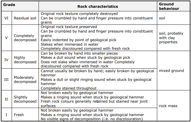
Table: Guide to rock and soil descriptions
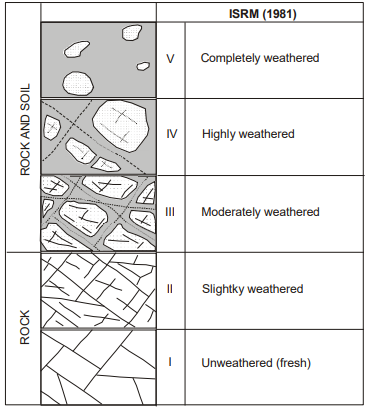
Table: Effect of weathering on the geomechanical properties
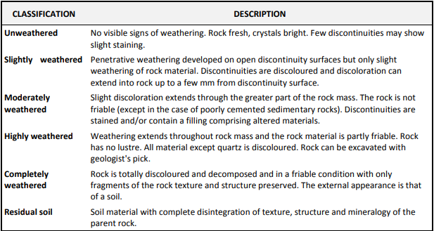
Table: Engineering classification of the weathering of rocks

Table: Weathering/alteration
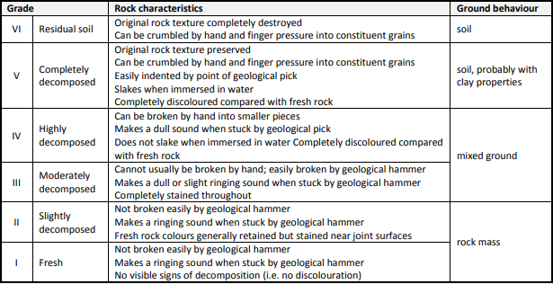
Table: Guide to rock and soil descriptions
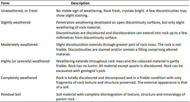
Table: Terminology of weathering and alteration
Q10) Explain measurement of velocity of sound in rock.
A10)
‐ a longitudinal or compression wave which travels with velocity Vp
‐ a shear or transverse wave which travels with velocity Vs
These velocities are related to the elastic constants by
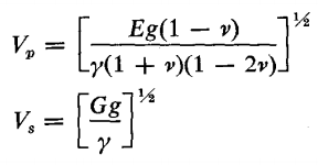
E = Modulus of elasticity, G = Modulus of rigidity (or Shear modulus) ν= Poisson’s ratio, g = gravitational acceleration, γ= Unit weight of the material
G can be determined from the shear wave velocity, Vs,without the knowledge of the Poisson’s ratio, ν. However, the determination of the Elastic modulus E requires the value of ν. Based on the relationship:

Both the E and ν can be determined by the following equation:
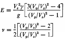
Also from the relationship

The bulk modulus K can be determined

Range of P wave velocity and S Wave Velocity of Intact Rocks
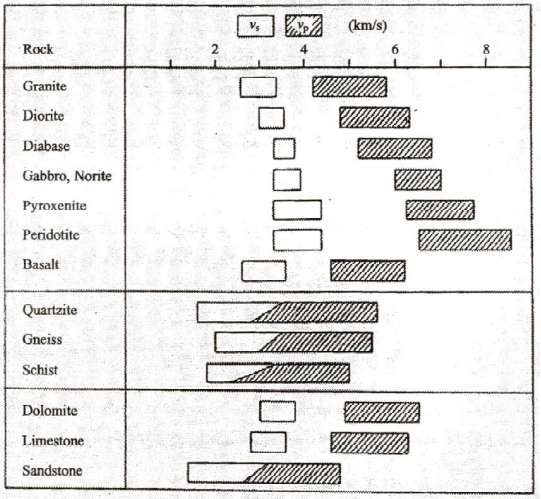
Fig. Range of P-wave velocity vp and S-wave velocity vs of different rocks
Q11) Classify rock material strength in detail.
A11)
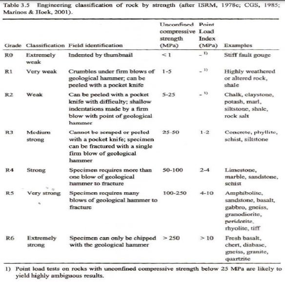
Table: Classification of rock by the strength
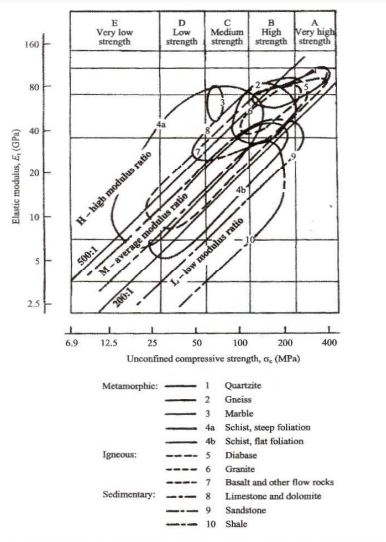
Fig. Classification of intact rocks
Q12) Explain core lopping in detail with organization of the log, heading and general information.
A12) Core logging
For engineering geology purposes, the basic objectives of logging core are to provide a factual, accurate, and concise record of the important geological and physical characteristics of engineering significance. Characteristics that influence deformability, strength, and water conditions must be recorded appropriately for future interpretations and analyses. Reclamation has adopted recognized indexes, nomenclature, standard descriptors, and descriptive criteria, and alphanumeric descriptors for physical properties to ensure that these data are recorded uniformly, consistently, and accurately. The use of alphanumeric descriptors and indexes permits the analysis of data by computer.
Exploration should be logged or, as a minimum, reviewed by an experienced engineering geologist. The logger should be aware of the multiple uses of the log and the needs and interests of technically diverse users. The experienced logger concentrates on the primary purposes of the individual drill hole as well as any subordinate purposes, keeping in mind the interests of others with varied geological backgrounds including geotechnical engineers, contract drillers, construction personnel, and contract lawyers. An experienced logger tailors the log to meet these needs, describing some seemingly minor features or conditions that have engineering significance, and excluding petrologic features or geologic conditions having only minor or academic interest. Less experienced loggers may tend to concentrate on unnecessary garnishment, use irrelevant technical terms, or produce an enormously detailed log that ignores the engineering geology considerations and perhaps the purpose for completing the drill hole.
Organization of the Log
The log forms are divided into five basic sections: a heading block; a left-hand column for notes; a center column for indexes, additional notes, water tests, and graphics; a right-hand column for classification and physical conditions; and a comments/explanation block at the bottom.
Heading
The heading block at the top of the form provides spaces for supplying project identifying information, feature, hole number, location, coordinates, elevation, bearing and plunge of the hole, dates started and completed, and the name(s) of the person(s) responsible for logging and review. Locations should preferably be in coordinates unless station and offset are all that is available.
Data Required for the "Drilling Notes" Column
Data for the left-hand column of all drill hole logs are similar whether for large-diameter sampling, Standard Penetration Tests, rock core, or push-tube sampling logs. These data are field observations and information provided by the driller on the Daily Drill Reports. Examples are provided for some of these data headings; a suggested guideline and preferred order is presented in the following paragraphs but may differ depending on the purpose and type of exploration. Headers for data can indicate whether depths are in feet (ft) or meters (m), eliminating the need to repeat "ft" or "m" for each interval entry.
General Information.
This includes headers and data for the whole purpose, the setup or site conditions, drillers, and drilling and testing equipment used.
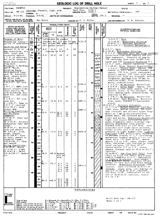
Fig. Drill hole log.
Q13) What is rock quality designation?
A13) Rock Quality Designation
In Civil engineering, different parameters are used to characterize the quality of the rocks. Evaluation of the mechanical properties of the rocks and characteristics of rocks is one of the challenging parts of rock engineering. Rock mass has wide applications in the construction of structures, excavation, and tunnels and maintaining stable slopes.
Hence, there must be a perfect parameter that is used to evaluate the Quality and the Properties of the rock mass.Rock Quality Designation is widely used as a crude indicator to evaluate the quality of rock mass and its properties.
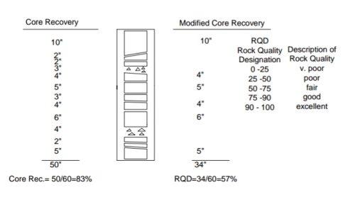
Rock Quality Designation is a parameter used to measure the degree of jointing or fracture in the rock mass.In simple words, the Rock quality designation is nothing but the measure of the quality of the rock which is obtained from the borehole.It is generally measured as the percentage of the drill cover in the length of 10cm or more.
The Rock quality designation index was developed by Deere in the year 1964.RQD (Rock quality designation ) signifies the degree of jointing or fracture in a rock mass measured in percentage, where RQD of 75% or more shows good quality hard rock and less than 50% shows low quality weathered rocks.
The pieces of rock are considered of hard and good quality. The length of core pieces of Rock mass is measured along the centerline of the pieces.
While measuring the index there should not be inconsistency in the measurement.
Core Recovery Calculation

Rock quality designation is generally calculated by taking the sample of rock mass which is obtained from a borehole.
RQD =[(Sum of the length of core greater than 10 cm) X 100] divided by the total length of the core run
The Rock quality designation (RQD) is generally expressed in the Percentage (%).
In the rock quality designation, the surface is drilled at a certain depth, and with the help of the core property of the rock, mass is determined.
For determination of Rock quality designation using core boring, the International Society for Rock Mechanics (ISRM) has recommended a core size of at least N X (size 54.7 mm) drilled with a double-tube core barrel using a diamond bit.
Condition of the Rock as Per There Rock Quality Designation.
Condition of the Rock | RQD in % |
Very poor completely (weathered rock) | Less than 25% |
Poor (weathered rock) | 25 to 50% |
Fair moderately (weathered rock) | 51 to 75% |
Good (hard rock) | 76 to 90% |
very good( fresh rocks) | 91 to 100% |
The determination of rock mass strength using the technique of RQD can be performed in the field or the laboratory.
Determination of the deformation modulus and unconfined compressive strength of jointed rock masses is a crucial and challenging part of rock mechanics and rock engineering.
The empirical methods which are based on Rock Quality Designation provide a very convenient way for estimation of the deformation modulus and unconfined compressive strength of rock masses.
In many cases, The Rock quality designation (RQD) is the only available data about the discontinuity in the routine site investigation.
RQD is the only factor that affects the deformability and the strength of jointed rock mass.
Q14) What are the advantages of rock quality designation and rock mass description?
A14) Advantages of Rock Quality Designation
Limitations of Rock quality designation(RQD)
The problem with uncertainties in rock engineering
The great spatial variability and large volumes involved in rock mass utilizations result in only a limited number of measurements that can be made in a characterization. Before construction, the subsurface, therefore, has to be described by a limited number of imprecisely known parameters. Considerable uncertainties may be introduced from the interpretation and extrapolation made to describe the geological setting. Also, the fact that horizontal weakness zones and other features, which do not outcrop, may be overlooked, is added to these errors.
Thus, although extensive field investigation and good quality descriptions will enable the engineering geologist to predict the behavior of a tunnel more accurately, it cannot remove the risk of encountering unexpected features. Good quality characterization of the rock mass will, however, in all cases except for incorrect interpretations, improve the quality of the geological input data to be applied in evaluations, assessments, or calculations and hence lead to better designs.
After the rock mass has been "opened" during excavation, the actual rock masses may be studied. In these cases, the quality of the input data used in evaluations, calculations, and modeling mainly depends on the way they are measured and characterized.
A methodology for strength characterization of rock masses
As a rock mass is composed of intact rock penetrated by joints, its behavior depends not only on the properties of the intact material and the discontinuities separately but also on the way they are combined. Thus, several complications arise when the parameters of a rock mass shall be described:
1. The intact rock is inhomogeneous and variable.
2. The discontinuities are diverse (i.e. their variations involve more than ten characteristics).
3. The geometrical arrangement of discontinuities is infinitely variable.
Because of these structural variations and the often large volumes involved, the properties of a rock mass have to be determined from observations backed by laboratory tests of small specimens. Thus, the evaluations and assessments applied in engineering are largely empirical, typically applied in the classification schemes.
The rock mass index (RMi) developed in this work is a general characterization of rock masses in which their main parameters are included. In principle, it is based on the reduction in the strength of the intact rock due to the presence of joints. This is expressed as
RMi = σc× JP
where σc is the uniaxial compressive strength of intact rock measured on 50 mm samples;
JP is the jointing parameter, i.e. the reduction factor from jointing. It consists of :
- the degree of jointing (given as block size); and
- the joint characteristics, representing the joint wall roughness and alteration, as well as the size of the joint.
Q15) Explain use of RMI in rock engineering with rock mass classification in detail.
A15) The use of RMi in rock engineering
As a relative strength index for rock masses, the RMi expresses numerically the quality of the rock mass. RMi may be applied in various methods used in practical rock engineering. Besides, some of the parameters in RMi can be used individually in classification systems on stability, where they may improve the input and/or because they may be easier and or more accurately characterized.
Rock Mass Classification
To derive the overall behavior of a rock mass, both the engineering properties of the rock material and the fractures should be taken into consideration. The most significant parameters that are used in classification systems are the following:
Common rock mass classification systems
Most of the multi-parameter rock mass classification systems were developed from civil engineering case histories. Those that are commonly used in rock mechanics to assist designing in infrastructure are the following:
Introduced by Terzaghi in 1946, the system evaluates the impact of rock load on steel-supported tunnels based on a descriptive classification of rock classes.
The RMR system was developed by Bieniawski in 1973 to derive the required support measures for tunnels. The system is practical as it uses a few basic parameters. Since its conception, it has been tested and improved by many case studies.
The Q-system was introduced by Barton, Lien, and Lunde in 1974 and its purpose was to determine the rock mass characteristics and tunnel support measures based on 212 hard rock tunnel case histories from Scandinavia. Q-rating is derived by assigning values to six parameters that are grouped into three quotients.
GSI was introduced by Hoek in 1994. Its purpose was to derive the rock mass properties by using in-situ observations of the rock mass conditions along with correlations developed from the RMR-system. GSI utilizes 2 main parameters, the rock mass structure and the discontinuity surface quality.