Unit-1
Analysis Of Indeterminate Structure by force methods
Q1) What is analysis of indeterminate structure by force methods? And explain flexibility method in detail.
A1)
Analysis of indeterminate structure by force methods
The pressure approach of analysis, additionally known because the approach of steady deformation, makes use of equilibrium equations and compatibility situations to decide the unknowns in statically indeterminate systems. In this approach, the unknowns are the redundant forces. For indeterminate systems , Statics (equilibrium) on my own isn't always enough to behavior structural analysis. Compatibility and fabric facts are essential.
Indeterminate structure:
Advantages:
Disadvantages:
Techniques of analysis there are most important techniques:
Flexibility Method or Method of Consistent Deformation:
Q2) Explain static indeterminacy and sign conventions in detail.
A2) Static Indeterminacy
The Static Indeterminacy (SI) for beams and frames is described as,
SI = nu — ne
Where,
nu = Number of unknown assist reactions
ne = Number of equations of equilibrium
In fashionable for a -dimensional shape, there are 3 equations of equilibrium (ne = 3) and for a 3-dimensional shape there are six (ne = 6).
For a truss, static indeterminacy entails each outside and inner indeterminacy due to the inner individuals in a truss.
Static indeterminacy (SI) within side the case of a truss is described as,
SI = b + r — 2j
Where,
b = Number of individuals within side the truss
r = Number of reactions on the supports
j = Number of joints within side the truss
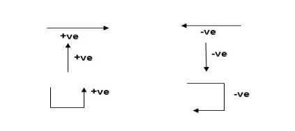
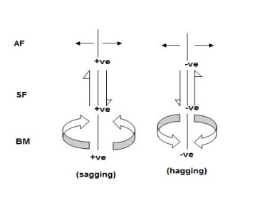
Sign Conventions
1). Static Calculations
∑F x = 0, ∑F y = 0 & ∑M = 0
2). For Structural Actions
Q3) Explain degree of static indeterminacy with example.
A3) Degree of static indeterminacy (Dsi)
Dsi = No of Unknown Actions –No of Eqn,
Dsi = R – E
External Indeterminacy
When we can't discover assist reactions the use of legal guidelines at statics, it's miles referred to as externally indeterminate structure.
Internal Indeterminacy
When we can't discover inner member movements the use of legal guidelines of statics, it's miles referred to as internally indeterminate structure.
Boundary condition
Displacement Re stained Displacement allow
Δx, Δy, ϴz Nil
Δy,ϴz, Δx
Δx, Δyϴz
Dsi for beams = R – E
Where,
R = No of assist reactions
E = No of Equilibrium equations
Note: For one inner pin, no of extra equations of equilibrium are = m – 1
m = no of individuals linked via way of means of pin.
Sr. No Structure
1. 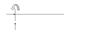
R E Dsi
3 3 0
2. 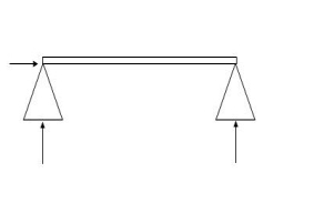
R E Dsi
3 3 0
3. 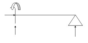
R E Dsi
4 3 1
4. 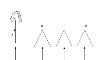
R E Dsi
6 3 3
5. 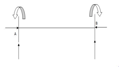
R E Dsi
6 3 3
6. 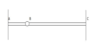
R E Dsi
6 4 4
7. 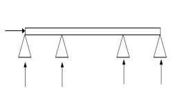
R E Dsi
5 4 1
8. 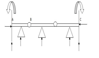
R E Dsi
9 5 4
Q4) How to calculate Dsi for trusses?
A4) Dsi for Trusses:
(Dsi)Total = (m + R) – (2J)
Where,
M = No of members
R = No of support reactions
J = No of Joints
(Dsi)external = R – 3
(Dsi)internal = (Dsi)total – (Dsi)ext
Dsi = (M + R) – 2j
Sr. No Truss
1. 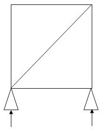
M R J (Dsi)Total
5 3 4 0
2. 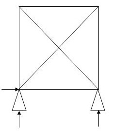
M R J (Dsi)Total
6 3 4 1
(Dsi)int.=0
(Dsi)ext= 1
3.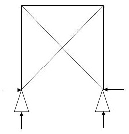
M R J (Dsi)Total
5 4 4 1
(Dsi)int.=1
(Dsi)ext= 0
4. 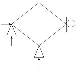
M R J (Dsi)Total
5 4 4 1
(Dsi)int.= 1
(Dsi)ext= 0
5. 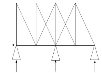
M R J (Dsi)Total
19 4 10 3
(Dsi)int.= 1
(Dsi)ext= 2
6. 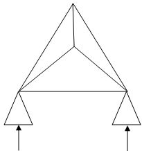
M R J (Dsi)Total
6 4 4 2
(Dsi)int. = 1
(Dsi)ext = 1
7. 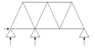
M R J (Dsi)Total
11 4 7 1
(Dsi)int. = 1
(Dsi)ext = 0
8. 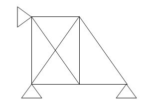
M R J (Dsi)Total
8 4 5 2
(Dsi)int.= 1
(Dsi)ext = 1
9. 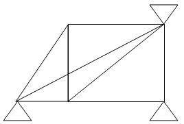
M R J (Dsi)Total
8 5 5 3
(Dsi)int. = 2
(Dsi)ext = 1
10. 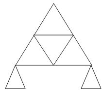
M R J (Dsi)Total
9 3 6 0
Q5) How to calculate Dsi for frames?
A5) Dsi for Frames:
(Dsi)Total = 3m + R – 3J
(Dsi)external = R – 3
(Dsi)Internal = (Dsi)Total – (Dsi)ext
Sr. No Structure
1. 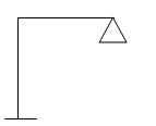
M R J (Dsi)Total
2 5 3 2
2.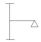
M R J (Dsi)Total
3 8 4 3
3. 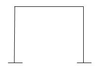
M R J (Dsi)Total
6 6 6 6
4. 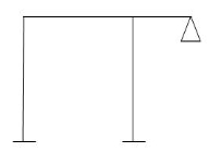
M R J (Dsi)Total
4 8 5 5
5. 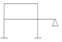
M R J (Dsi)Total
3 8 11 10
6. 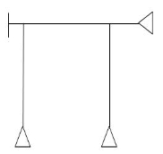
M R J (Dsi)Total
5 9 6 6
7. 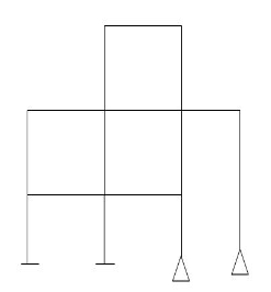
M R J (Dsi)Total
15 10 13 16
Q6) How to calculate Dki for frames?
A6) Dki for beams:
1)

2) 
ϴB = 1
3) 

4)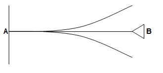
ΔYB&ϴB = 2
5)
ϴB, ϴC, ϴD = 3
6) 
ϴB, ϴC, ϴDΔYD = 4
7) 
= 0
8) 
ϴBA, ϴBC, ΔBy = 3
9) 
ϴB, ΔBy = 2
10)
ϴDE, ϴDC, ΔDy = 6
ϴC, ϴBΔBy
11) 
ϴA, ϴB,
ϴD, ϴCB, ϴCD = 10
ΔYC, ϴE
ΔYE, ΔYF1, ϴE
Q7) Explain application of force method to analysis of indeterminate beam and what is flexibility coefficient?
A7) Application of Force Method to Analysis of Indeterminate Beams:
Calculate the Static Indeterminacy (SI) of the shape the use of equation relying upon whether or not the shape is beam, frames, or truss.
Choose one of the response forces (or internal participants of the truss) because the redundant pressure. One at a time if there are more than one redundancy.
Split the statically indeterminate shape right into a determinate shape (acted upon via way of means of implemented hundreds at the shape) and determinate shape(s) acted on via way of means of the redundant forces (one at a time).
Analyze the determinate systems via way of means of the unit load approach to locate the displacement AL, that's the displacement for the implemented loading and redundant removed. Then locate at, that's the displacement for the unit load only, on the factor of redundancy. If a second is taken as redundant, the corresponding displacements may be zero and a
Finally, formulate equation(s) of displacement compatibility on the support(s) (within side the case of beams and frames). In the case of trusses, displacement compatibility of truss bars may be used.
Solve those equation(s) to get the redundant pressure(s).Calculate all of the reactions on the support the use of standards of statics.
Flexibility coefficient:
The flexibility approach is primarily based totally upon the answer of "equilibrium equations and compatibility equations". There will continually be as many compatibility equations as redundant. It is referred to as the flexibility approach due to the fact flexibilities seem within side the equations of compatibility. Another call for the approach is the pressure approach due to the fact forces is the unknown portions in equations of compatibility.
Q= [DQL]+[F][Q]-compatibility equation
DQ=External displacement at redundant position
 Displacement at the redundant position because of applied loading

F=flexibility matrix


Q8) Explain Redundant reaction of given example.
A8) Redundant reaction
It is also called as Force Method
In this method, horizontal displacement is neglected
Degree of indeterminacy=R-E
R=Reaction
E=Equilibrium equation


=4-2
=2
The redundant structure is 2.

Use flexibility Matrix Method
Step 1)


=4-2
=2
Redundant structure is 2.

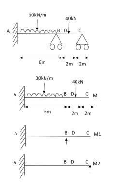
Zone | Limit | Origin | M |
|
|
CD | 0-2 | C | 0 | 0 | x |
DB | 0-2 | D | -40 | 0 | x+2 |
BA | 0-6 | B |
| x | x+4 |


 = - 11100 /EI


=333.33/


Q9) Explain energy method and strain energy in detail.
A9) Energy methods:
These are methods primarily based totally on linear elastic conduct and conservation of electricity, Energy U = Fx/2 = F2/2k wherein F is the implemented pressure, x is the space moved within side the route of the pressure at its factor of utility and okay is the elastic stiffness of the part, once more within side the route of the pressure at its factor of utility. , i.e. the work done via way of means of outside forces equals the electricity saved within side the structural below
Strain Energy
1) EI = 17250 Kn.m2 find strain energy?
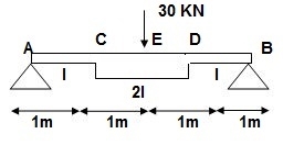
∑MA = 0
30 x 2 – RB x 4 = 0
RB = 15
VA = VB = 15 KN
BMC = BMD = 15(1) = 15 KN.m
BMC = 15(2) = 30 KN.m
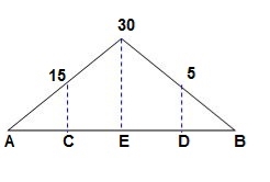
2) ‘M/EI’ Dia.
3) C.B
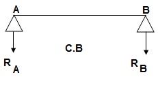
A1 = 1 / 2 x 1 x 15/EI = 7.5/EI
A2 = 2 x 7.5/EI = 15/EI
A3 = 1 /2 x 2 x 7.5/EI = 7.5/EI
A4 = 1 / 2 x 15/EI x 1 = 7.5/EI
Analysis of conjugate beam
∑MA = -RB(4) + 1/EI{7.5(2/3 x 1) + 15(2) + 7.5(2) + 7.5(3 + 1/31)} = 0
= - RB x 4 + 1/EI[ 5 + 30 + 15 + 25 ] = 0
RB x 4 = 75/17250
RB = 18.75/EI
∑fy = 0
-RA + RB + A1 + A2 + A3 + A4 = 0
RA = 18.75/EI
RA = RB = ½{A1 + A2 + A3 + A4} = 18.75/EI
Slope & Deflection
(ϴA)R.B = (SFA)C.B = (-)18.75/EI

 = 18.75/EIxC = 1.086 x 10⁻³radxC

 (ϴB)R.B = (SFB)C.B = 18.75/EIxC = 1.086 x 10⁻³ rad xC
(ΔE)R.B = (BME)CB
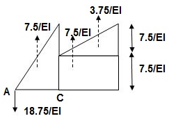
(BME)CB= 1/EI{ -18.75 + 7.5(1 + 1/3 x 1) + 7.5(0.5) + 3.75 (1/3 x 1)}
=1/EI{-22.5}

 ΔE = 22.5/EI xC = 1.304 mm xC
Q10) Explain principle of minimum potential strength and explain principle of virtual work.
A10) Principle of minimum potential strength:
The minimal overall capability strength precept is a essential idea used in engineering. It dictates that at low temperatures a shape or frame shall deform or displace to a role that (locally) minimizes the overall capability strength, with the misplaced capability strength being transformed into kinetic strength. His general capability strength is the sum of the elastic stress strength, U, saved within side the deformed frame and the capability strength, V, related to the implemented forces
Π = U + V (1)
This strength is at a desk bound function whilst an infinitesimal version from such function entails no alternate in strength
δ Π = δ ( U + V ) = 0 (2)
The precept of minimal general capability strength can be derived as a unique case of the digital work precept for elastic structures issue to conservative forces.
The equality among outside and inner digital work (because of digital displacements) is:
∫ S t δ u T T d S + ∫ V δ u T f d V = ∫ V δ ϵ T σ d V (3)
In the unique case of elastic bodies, the right-hand-aspect of (3) may be taken to be the alternate, of elastic stress strength U because of infinitesimal versions of actual displacements. In addition, whilst the outside forces are conservative forces, the left-hand-aspect of (3) may be visible because the alternate within side the capability strength function V of the forces. The function V is described as
V = − ∫ S t u T T d S − ∫ V u T f d V
Where in: the minus signal implies a lack of capability strength because the force is displaced in its direction. With those subsidiary conditions, (3) becomes:
− δ V = δ U
This leads to (2) as desired. The variation shape of (2) is frequently used as the idea for growing the finite detail approach in structural mechanics.
Principle of virtual work:
Virtual work is the work done with the aid of using a actual pressure appearing via a digital displacement or a digital pressure appearing via a actual displacement.
The Unit Load Method When the precept of digital work is used to calculate the displacement, at a co-ordinate, the device of outside forces,̄ F"> is selected for you to consist best of a unmarried unit pressure at coordinate.
A digital displacement is any displacement constant with the restrictions of the shape, i.e., that fulfill the boundary situations on he supports.
A digital pressure is any device of forces in equilibrium. f(x) and y(x) are actual forces and related displacements. ̄y(x) is a digital displacement constant with the boundary situations.
Q11) Explain the process of Castiglione s theorem in detail.
A11) Castiglione’s 1st theorem:
It states that displacement at a point of application of load in the direction of load is equal to partial derivative of strain energy of structure with respect to load.
1]. ӘU/ӘQi = Δj
U = strain energy
Qj = Force in the direction j
Δj = Displacement in the direction j
2]. Strain energy: Uaxial force = ∫L0P2dx/2EA
UB.M = ∫L0M2dx/2EI
UTorsion = ∫L0T2dx/2GJ
Deflection = translation
3]. Procedure of displacement analysis by Castigliano’s theorem :
Step 1:
Apply imaginary load ‘Q’ at section where displacement is required.
Note:
1>. For horizontal translation apply ‘Q’ in horizontal direction for vertical translation apply force Q in vertical direction
2>. For finding ‘slope’(rotation) apply couple Q.
Step 2:. Find support reactions and draw member F.B.D’s
Step 3: Prepare table:
Zone origin limits EI M ӘM/ӘQ
Step 4: Find displacement using Δj = ∫L0M/EI{ӘM/ӘQj} dx
Find ΔB :

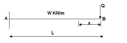
Zone Origin Limits EI M ӘM/ӘQ
BA B 0 to L EI –Q(x) – W(x2/2)-x
ΔB = ∫L0 M/EI (ӘM/ӘQ)dx = ∫L0 {-W(x2/2)}(-x)dx
= W/2EI{x4/4}L0
 ΔB = WL4/8EI ( )
Q12) Find vertical deflection at C.
A12) EI = constant
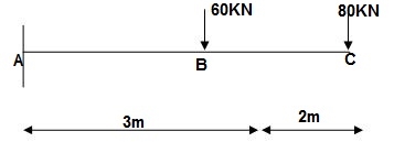
M Diagram
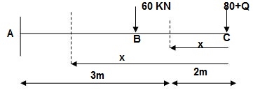
From above Fig :
Table
Zone Origin limits EI M ӘM/ӘQj
CB C 0-2 EI -(80 + Q)x - x
BA C 2-5 EI -(80 + Q)x - x
-60(x-2)
ΔC = ∫20-(80)x/EI {-x}dx + ∫52{80x – 60(x-2) (-x)dx/EI}
= ∫2080x2/EIdx + ∫52{80x2 – 60x2 + 2x}dx/EI
= 1/EI{213.33 + 4200}
 ΔC = 4413.33/EI( )
Q13) Find vertical deflection at point C.
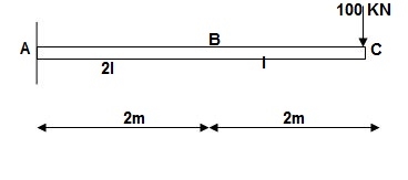
A13)
M Diagram
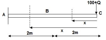
Zone Origin Limit EI M ӘM/ӘQ
CB C 0 – 2 EI - (100 + Q)x -x
BA C 2 – 4 EI -(100 + Q)x -x
ΔC = ∫20 – 100x/EI(-x)dx + ∫42 -100x/EI(-x)dx
= ∫20100x2/EI dx + ∫42100x2/2EIdx
= 266.66 + 1866.6/2 = 266.66 + 933.33
For cantilever always write load from free end. For simply write load from supports.
ΔC = 1200/EI
Q14) Find slope at A and deflection at C.
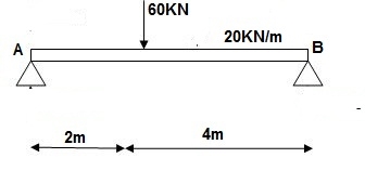
A14) M Diagram
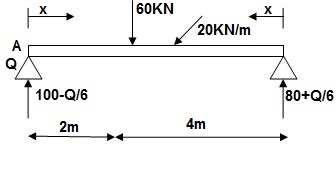
Reactions in M dia.
∑MA = VB(6) – 20 x 6 x 3 – 60(2) – Q = 0
VB = 80 + Q/6
∑Fy = VA + VB – 60 – 20 x 6 = 0
VA = 100 – Q/6
Zone Origin limits EI M ӘM/ӘQ
AC A 0 – 2 EI (100-Q/6)(x) 1 – x/6 + Q – 20(x2/2)
BC B 0 – 4 EI (80+Q/6)(x)-20x2/2 x/6
ϴA = ∫20{100(x) – 10x2}{1-x/6}dx/dEI + ∫40{80x – 10x2}x/6dx/EI
= 1/EI{135.55 + 177.78}
 ϴA = 313.32/EI( )
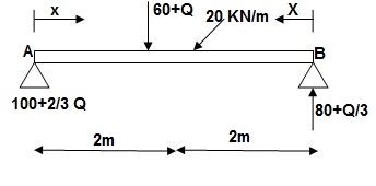
∑MA = VB(6) – 20(6)(3) – (60 + Q)2 = 0
VB = 80 + Q/3
∑Fy = VA + VB – (60 + Q) – 20(6) = 0
VA = -80 – Q/3 + 60 + Q + 120 = 0
VA = 100 + 2/3Q
Q15) Find deflection at point C

A15)
M Diagram
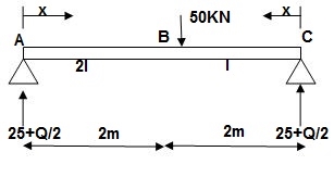
Zone Origin Limit EI M ӘM/ӘQ
AC A 0 – 2 EI (25 + Q/2)x x/2
BC B 0 – 2 EI (25 + Q/2)x x/2
ΔC = ∫20(25x)x/2dx/EI + ∫2025x(x/2)dx/2EI
= 33.33 + 16.66/EI
 ΔC = 50/EI( )
Q16) Find deflection at D.
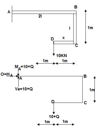
A16)
∑MA = MA – (10+Q)(1) = 0
MA = 10 + Q
∑Fy = VA – (10 + Q) = 0 VA = 10 + Q
∑Fx = HA = 0
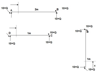
Zone origin limits EI M ӘM/ӘQ
AB A 0 – 2 2EI (10+Q)x-(10+Q) x-1
CB C 0 – 1 EI -(10 + Q) -1
DC D 0 – 1 EI -(10 + Q)x - x
ΔDy = ∫20(10x - 10)(x-1)dx/2EI + ∫10 -10(-1)dx/EI + ∫10 -10x(-x)dx/EI
= 3.33 + 10 + 3.33/EI
 ΔDy = 16.66/EI ( )
Q17) Explain Castiglione s second theorem in detail.
A17) Castiglione’s second theorem
Basics (1)
Beam fixed at both end is called as Fixed beam
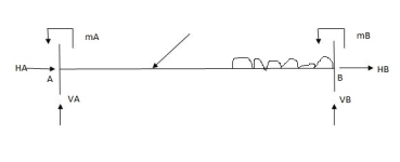
ii) Fixed beam is statically indeterminate
no. of unknown Reactions = R=6
no. of Equilibrium equation = E=3
Dsi – R-E = 6-3 =3
Note :
For beam subjected to vertical loads lonely-horizontal reactions are zero.
For Fixed beam subjected to vertical loads only.
no. of unknown Reactions = R=4
no. of Equilibrium equation = E=2
Dsi – R-E = 4-2 =2

For vertically downward load fixed and moments are begging in nature.


4) Advantages of fixed beam
Slope and deflection for fixed beam are less as compared to simply supported beam
Net sagging moment for fixed beam is less
Bending moment is better distributed over the length of member.
Fixed beam bar more resistance to impact loading
5) For fixed beam,
Tangents drawn at both ends are horizontal therefore angle betn tangents is equal to area of  Diagram is equal to zero.

1= Area  ‘Dia’ =0
Position of B with respect to tangent drawn at A
BA = Area  Dia
Dia =0
=0
Q18) A simply supported beam is subjected to loads as shown in fig. using influence lines find
support reactions
shear force & bending moment at ‘C’
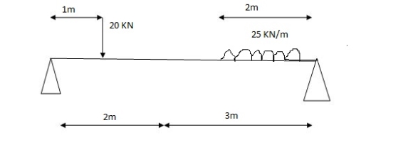
A18)
1) VA& VB
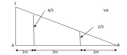
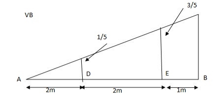
VA = 20 + 25 1
 = 16 + 10 = 26 KN
VB = 20  + 25
+ 25  +
+  = 4 + 40 = 44 KN


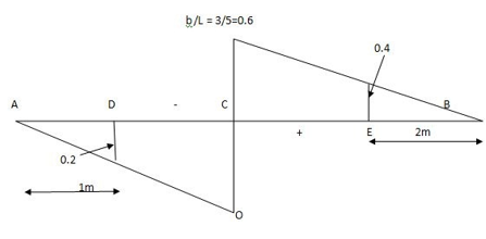
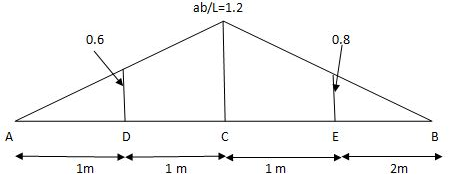
SFc = 20 (-0.2) + 25= 5KN
BMc = 20 (0.6) +  (2 0.8) (25)
= 32 KN. M


