Unit – 3
Tension members
Q1) Write a short note on tension members.
A1) Tension members are structural elements which are subjected to axial tensile forces. Examples of anxiety members are bracing for homes and bridges, truss members, and cables in suspended roof systems.
In an axially loaded anxiety member, the strain is given by:
F = P/A
Where in P is the importance of the burden and A is the pass-sectional place.
Q2) Describe design of tension members.
A2) To layout anxiety members, it is crucial to examine how the member might fail beneath Neath each yielding (excessive deformation) and fracture, which can be taken into consideration the restriction states. The restriction nation that produces the smallest layout energy is taken into consideration the controlling restriction nation. It additionally prevents the shape from failure.
Using American Institute of Steel Construction standards, the last load on a shape may be calculated from one of the following combination:
1.4 D
1.2 D + 1.6 L + 0.5 (Lr or S)
1.2 D + 1.6 (Lr or S) + (0.5 L or 0.8 W)
1.2 D + 1.6 W + 0.5 L + 0.5 (Lr or S)
0.9 D + 1.6 W
L= 14
Q3) Explain step wise design of tension member.
A3)
1. Corresponding to the loading on the shape of which the anxiety member is a part, the tensile pressure withinside the member is first computed.
2. The internet vicinity required for the member is decided via way of means of dividing the tensile pressure withinside the member via way of means of the permissible tensile pressure.
3. Now, an appropriate phase having gross vicinity approximately 20 in step with cent to twenty-five in step with cent extra than the predicted vicinity is decided on. For the member decided on deductions are made for the vicinity of rivet holes and the internet powerful vicinity of the phase is decided. If the internet vicinity of the phase of the member so decided is extra than the internet vicinity requirement predicted in step i, the layout is taken into consideration safe.
4. The slenderness ratio of an anxiety member shall now no longer exceed 400. In the case of an anxiety member vulnerable to reversal of pressure because of the motion of wind or earthquake, slenderness ratio shall now no longer exceed 350. If the reversal of pressure is because of masses others than wind or earthquake, the slenderness ratio shall now no longer exceed 180.
Q4) Give maximum values of slenderness ratio.
A4)
Q5) Explain displacement of tension members.
A5) The increase in the length of a member due to axial tension under service loads is
A = PL/(EAg)
where is the axial elongation of the member (mm),
P is the axial tensile force (un-factored) in the member (N),
L is the length of the member (mm), and
E is the modulus of elasticity of steel = 2.0 x lo5 MPa
Q6) What is shear lag?
A6)
Q7) State modes of failure of tension members.
A7) The extraordinary modes of failure in anxiety contributors are
1. Gross segment yielding
2. Net segment rupture
3. Block shear failure
Q8) Explain factors that effect on shear lag.
A8)
1. The thickness of the member does not play a role in the determination of shear lag factor or it does not affect the tensile capacity of the section.
2. If the distance between the plane of connection and the centroidal axis of the outstanding leg increases, it reduces the tension capacity of the section.
3. From the experimental studies, it is proved that if the length of the connection is increased up to 4 bolts, the tensile capacity increases. And if we further increase the length, it does not have a significant effect. (Kulak and Wu, 1997).
Q9) What is called as lug angles?
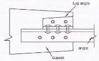
A9) Lug angles are sometimes used to reduce the length of connections. Figure below shows the lug angle connection with single or a channel type of tension member.

Due to the possible deformation of the outstanding leg of the lug angle, the rivets connecting the gusset plate with the lug angle will share less load than the rivets connecting the main member with the gusset plate.
Q10) what is compression members?
A10)
Q11) Enlist types of column bases.
A11)
(i) Slab base
(ii) Gusseted base
(i) Slab Base:
In this association the column stands at once over a metal base plate which rests over a concrete basis. The base plate is attached to the column flanges with connecting angles with the aid of using welding or bolting. The column-base plate unit is geared up withinside the concrete basis with basis bolts.
(ii) Gusseted Base:
Gusseted base plates are used for columns sporting heavy loads. In this example fastenings are used to connect the bottom plate and the column withinside the shape of gusset plates, angles etc.
Compression contributors of roof trusses are composed of unmarried angles or double angles. These contributors can be non-stop contributors (just like the fundamental rafter of the roof truss) or discontinuous contributors (just like the vertical and diagonal contributors of the truss).
Q12) What is single angle strut?
A12) The compressive pressure in unmarried perspective can be transferred both concentrically to its centroid via cease gusset or eccentrically with the aid of using connecting one in all its legs to a gusset or adjacent member.
Q13) Write short note on Strength of compression member.
A13)
Q14) What are continuous members?
A14)
Q15) What is Discontinuous members?
A15)
Q16) Explain Double Angle Strut.
A16)
If the struts carry in addition to axial loads, loads which cause transverse bending, the combined bending and axial stress shall be checked as described for the columns subjected to eccentric loading. The tacking rivets should be provided at appropriate pitch.
Q17) Explain Gussets.
A17)
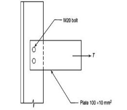
Q18) What is the net area A, for the tension member shown in Fig., in case of (a) drilled holes, (3) punched holes?

A18)
Ag = 100 x 10 = 1000 mm2
(a) Hole made by drilling Hole for M20 bolt = 22 mm
(b) Ag =Ag - n (hole x thickness of plate) = 1000 - 2 (22 x 10) = 560 mm2 (6) Holes made by punching Hole = 22 + 2 = 24 mm
(c) Ag = 1000 - 2(24 x 10) = 520 mm2
Q19) Write short note on Effective length of compression member.
A19)
(a) The effect of end restraints on column strength is usually incorporated in the design by the concept of effective length. (It must be emphasized that the concept of effective length is only a simple and convenient short cut and the designer is not obliged to use it, if helshe knows a better, yet sufficiently simple solution.)
(b) Hence, in this section the effective length concept is first explained for idealized boundary conditions and then extended to cases where intermediate restraints are present.
(c) The Julian and Lawrence alignment charts are used in American and Canadian codes.
(d) Note that Wood’s Curves (used in British and Indian codes), which are used to determine the effective length of columns of multi-story buildings are also explained.
Q20) Write note on built up compression members.
A20) For large loads and for efficient use of material, built-up columns (also called as combined columns or open-web columns) are often used.
They are generally made up of two or more individual sections such as angles, channels, or I-sections and properly connected along their length by lacing or battening so that they act together as a single unit. Such laced combined compression members are often used in bridge trusses. According to the type of connection between the chords, built-up members may be classified as follows: