Unit – 4
Design for flexural and flexural-torsional buckling
Q1) Define flexural bending.
A1) This kind of buckling can occur in any compression member that reviews a deflection as a result of bending or flexure. Flexural buckling takes place approximately the axis with the most important slenderness ratio, and the smallest radius of gyration.
Q2) Define Torsional buckling.
A2) This kind of buckling most effective takes place in compression individuals which might be doubly-symmetric and feature very narrow cross-sectional elements. It is as a result of a turning approximately the longitudinal axis. Torsional buckling takes place usually in built-up sections, and nearly by no means in rolled sections.
Q3) Define Flexural torsional buckling
A3) This kind of buckling most effective takes place in compression individuals which have unsymmetrical cross-segment with one axis of symmetry. Flexural-torsional buckling is the simultaneous bending and twisting of a member. This usually takes place in channels, structural tees, double-angle shapes, and equal-leg unmarried angles.
Q4) State methods to design flexural Buckling.
A4) Flexural Limit States Increasing the loading at the beam will sooner or later reason failure of the beam via way of means of either
• Yielding of the fabric and formation of a plastic hinge and a collapse mechanism
• Lateral-torsional buckling of the beam.
• Local buckling of the flange or net of a beam that isn't always compact Adequate lateral bracing of a beam will make certain that complete plasticity is done previous to lateral-torsional buckling occurring.
Using a form this is compact will make certain that complete plasticity is done previous to flange or net neighborhood buckling.
Q5) What is the effective length factor?
A5) The idea of the powerful duration elements of columns has been properly set up and broadly utilized by training engineers and performs an important role in compression member layout. The most structural layout codes and specs have provisions regarding the powerful duration issue. The powerful duration issue is received with the aid of using fixing the precise equations numerically which require many ordinary calculations or with the aid of using the usage of a couple of alignment charts for the 2 instances of braced frames and sway frames.
Q6) What are the parameters considered in effective length calculation?
A6) The following are the factors that will be consider during effective length calculation:
Clear Height
The clean top is the clean size between the restraining beams at the lowest of the stack and the restraining beams at the pinnacle of the stack. The clean top can be distinctive in every direction.
If, at an give up of the stack, no powerful beams or flat slab to encompass are found, then the clean top consists of the stack past this restraint, and the equal policies follow for locating the give up of the clean top on the give up of the following stack (and so on).
Effective Length
The effective length, le is calculated automatically - you also have the ability to override the calculated value.
le=K * l
where
l=clear height between end restraints
K=effective length factor
Q7) Write a short note on Sway Frames.
A7) A frame is considered to be non-sway (braced) if it is sufficiently braced by lateral bracing elements like structural walls. On the other hand, frames that provide lateral resistance only through columns are considered to be sway frames (unbraced).
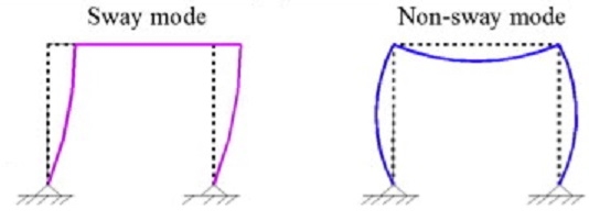
Q8) Differentiate sway and non-sway frame.
A8)
Sway (braced) Frames | Non-sway (unbraced) Frames |
Sway frames do not have adequate stiffness against in-plane horizontal forces, hence, additional forces or moments arising from horizontal displacements should be accounted for in the analysis | Non-sway frame response to in-plane horizontal forces is sufficiently stiff to neglect any additional forces or moments arising from horizontal displacements |
The structure is symmetric, and loading is symmetric | Loading is asymmetric |
It has only a rotational degree of freedom, and translational degree of freedom does not exist | It has in-plane displacements due to asymmetrical loading, different length of supports, and/or different moment of inertia |
Joints change their positions due to deformation | Joints do not change their position due to deformation |
Second-order analysis should be used | First-order analysis should always be used for the analysis of non-sway frame |
Q9) What is meant by framing system?
A9) For the purposes of analysis and design, steel frames have traditionally been regarded as belonging to one of two categories:
Of course, examples exist for which elements of both types are present; the present discussion does not consider these cases in developing the subject.
Q10) Elaborate types of framing systems.
A10)
Type of framing | Method of global analysis | Types of connections |
Simple | Pin joints | Nominally pinned Nominally pinned |
Continuous | Elastic | Rigid Nominally pinned |
Rigid-Plastic | Full-strength Nominally pinned | |
Elastic-Plastic | Full-strength - Rigid Nominally pinned | |
|
|
|
Q11) Write a note on Simple Construction.
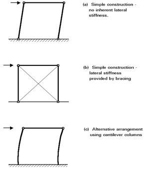
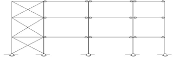
A11) Building frames designed and executed according to this principle require comparatively little analysis as the loads may be allocated to individual members on the basis of simple statics. Since the joints are assumed to be incapable of transmitting moments, lateral stability requires the use of bracing because a rectangular bay with pinned beam to column connections, of course, possess no lateral stiffness.
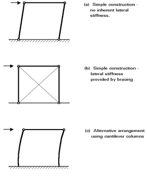
Q12) What is Continuous Construction?
A12) When rigid joints are used, considerable interaction between beams and columns occurs due to transfer of moments around the frame. Various approaches to analysis and design may be employed; the most important consideration is the extent to which the effects of deflections on the response of the frame must be taken into account.
Q13) Enlist the methods of analysis of frames.
A13)
Q14) What is simple Framing?
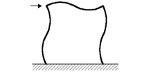
A14) The method for analysis and design of simple framing is dealt with at length The frame incorporates a separate bracing system which is designed to resist lateral loading and provide lateral stability to the part of the structure resisting gravity load (see Figure 9).
Q15) What are the assumption made in simple framing?
A15) The model assumes the following:
Q16) What are the general requirements in lacing?
A16) General Requirements for Lacing (IS 800):
(i) Compression members comprising two main components laced and tied, should where practicably have a radius of gyration about the axis perpendicular to the plane of lacing not less than the radius of gyration about the axis parallel to the plane of lacing.
(ii) As far as possible the lacing system shall be uniform throughout the length of the column.
(iii) Single laced systems on opposite faces of the components being laced together shall preferably be in the same direction so that one is the shadow of the other instead of being mutually opposed in direction.
(iv) The effective slenderness ratio (KL/r) e of laced columns shall be taken as 1.05 times the (KL/r) o, the actual maximum slenderness ratio, in order to account for shear deformation effects.
(v) Width of lacing bars – In bolted/riveted construction, the minimum width of lacing bars shall be three times the nominal diameter of the end bolt/rivet.
(vi) Thickness of lacing bars – The thickness of flat lacing bars shall not be less than one-fortieth of its effective length for single lacing and one-sixtieth of the effective length for double lacings.
(vii) Rolled sections or tubes of equivalent strength may be permitted instead of flats for lacings.
Q17) Write a note on Design of battens.
A17) Battens shall be designed to carry the bending moments and shear forces arising from transverse shear force Vt equal to 2.5 per cent of the total axial force in the whole compression member, at any point in the length of the member divided equally between parallel planes of the battens. Battened member divided equally between parallel planes of the battens.
Battened member carrying calculated bending moment due to eccentricity of axial loading, calculated end moments or lateral loads parallel to the plane of battens, shall be designed to carry actual shear in addition to the above shear.
Battens shall be of plates, angles, channels or I-sections and at their ends shall be riveted, bolted or welded to the main components so as to resist simultaneously a shear
Vb = (V1C)/N5 along the column axis and a moment M = (V1C)/2N at each connection.
where,
V1 = Transverse shear force as defined above
C = Distance between centre to center of battens, longitudinally
N = Number of parallel planes of battens, and
S = Minimum transverse distance between the centroid of the rivet/bolt group/welding connecting the batten to the main member.
Q18) Write a short note on Laterally supported and un supported beams.
A18) Laterally supported and un supported beams Generally, a beam resists transverse loads by bending action. In a typical building frame, main beams are employed to span between adjacent columns; secondary beams when used – transmit the floor loading on to the main beams. In general, it is necessary to consider only the bending effects in such cases, any torsional loading effects being relatively insignificant.
The compression flange of the beam is restrained from moving laterally, and
Any form of local buckling is prevented. If the laterally unrestrained length of the compression flange of the beam is relatively long as in category 2 of Table 1, then a phenomenon, known as lateral buckling or lateral torsional buckling of the beam may take place.
Q19) What are the factor that affect lateral stability?
A19) The elastic critical moment, Mcr, as obtained in the previous Section, is applicable only to a beam of I section which is simply supported and subjected to end moments. This case is considered as the basic case for future discussion. In practical situations, support conditions, beam cross section, loading etc. vary from the basic case. Refer IS code for details.
Q20) State design procedure of laterally supported beams.
A20)
1. Calculate design load.
2. Calculate design moment, M and bending stress, fb.
3. Select a trial beam size and calculate allowable bending stress, Fb (see problems)
4. Calculate deflection and check with allowable deflection ratio.
5. Calculate design shear and shear stress, fv.
6. Calculate allowable shear stress, Fv.