Unit-3
Stability of slopes
Q1) What is slope stability?
A1) An exposed ground surface that stands at an angle (β) with the horizontal is called slope. Slopes are required in the construction of highway and railway embankments, earth dams, levees and canals. These are constructed by sloping the lateral faces of the soil because slopes are generally less expensive than constructing walls. Slopes can be natural or man made. Slope stability analysis consists of determining and comparing the shear stress developed along the potential rupture surface with the shear strength of the soil.
slope stability analysis discuss the following.
Understand the forces and activities that provoke slope failures.
Understand the effects of seepage on the stability of slopes.
Estimate the stability of slopes with simple geometry for different types of soils.
The quantitative determination of the stability of slopes is necessary in a number of engineering activities, such as:
The design of earth dams and embankments,
The analysis of stability of natural slopes,
Analysis of the stability of excavated slopes,
Analysis of deep-seated failure of foundations and retaining walls.
Q2) What are the types of slopes?
A2) On the basis of method of construction:
Natural Slopes
The slopes formed due to natural process and exist naturally are called natural slopes. Natural slopes are those that exist in nature and are formed by natural causes. Such slopes exist in hilly areas. The sides of cuttings, the slopes of embankments constructed for roads, railway lines, canals etc and the slopes of earth dams constructed for storing water are examples of man-made slopes. The slopes whether natural or artificial may be
Artificial slopes
The slopes formed by unnatural process. Artificial slopes are formed by humans as per requirements.
On the basis of type of soil:
Types of slopes According to extent:
Infinite Slopes
The type of slope extending infinitely, or up to an extent whose boundaries are not well defined. For this type of slope the soil properties for all identical depths below the surface are same. In the making of natural slopes, there is no contribution from our side.
Finite Slopes
The slope that is of limited extent. We the engineers deal with this type of slopes. The term infinite slope is used to designate a constant slope of infinite extent. The long slope of the face of a mountain is an example of this type, whereas finite slopes are limited in extent. The slopes of embankments and earth dams are examples of finite slopes. The slope length depends on the height of the dam or embankment.
In recent years soil cement as a facing material for earth fill dams has been found economical where suitable rip-rap is not available near the site. A reasonably firm foundation is preferred so that deformation after placement of soil-cement is not significant; however, no unusual design features need be incorporated into the embankment.
Q3) Analysis of finite and infinite slopes
A3) Infinite Slopes in Dry Cohesionless Soils:
A typical section or “slice” through the potential failure zone of a slope in a dry cohesion less soil, e.g., dry sand, is shown in Figure 6-3, along with its free body diagram. The weight of the slice of width b and height h having a unit dimension into the page is given by:

where γ is the effective unit weight of the dry soil. For a slope with angle β as shown in Figure below:
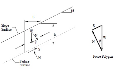
The normal (N) and tangential (T) force components of W are determined as follows:


The available shear strength along the failure plane is given by:

The factor of safety (FS) is defined as the ratio of available shear strength to strength required to maintain stability. Thus, the FS will be given by:

For an infinite slope analysis, the FS is independent of the slope depth, h, and depends only on the angle of internal friction, φ, and the angle of the slope, β. The slope is said to have reached limit equilibrium when FS=1.0. Also, at a FS = 1.0, the maximum slope angle will be limited to the angle of internal friction, φ.
Infinite Slopes in c-φ Soils with Parallel Seepage:
If a saturated slope in a c-φ soil has seepage parallel to the surface of the slope as shown in Figure below, the same limit equilibrium concepts may be applied to determine the FS, which will now depend on the effective normal force (N'). In the following analysis, effective shear strength parameters, c' and φ' are used.
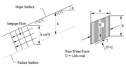
From Figure above, the pore water force acting on the base of a typical slice having a unit dimension into the page is:

where h is any depth less than or equal to the depth of saturation and b is a unit width.
The available frictional strength, S, along the failure plane will depend on φ' and the effective normal force, N' =N-U, where N is the total normal force. The equation for S is:

The factor of safety for this case will be:

By substituting W = γsat b h into the above expression and rearranging terms, the FS is given by:

where γ' = (γsat - γw).
For c' = 0, the above expression may be simplified to:

From Equation above it is apparent that for a cohesionless material with parallel seepage, the FS is also independent of the slope depth, h, just as it is for a dry cohesionless material as given earlier. The difference is that the FS for the dry material is reduced by the factor γ'/γsat for saturated cohesionless materials to account for the effect of seepage. For typical soils, this reduction will be about 50 percent in comparison to dry slopes.
The above analysis can be generalized if the seepage line is assumed to be located at a normalized height, m, above the failure surface where m =z/h. In this case, the FS is:
![FS=frac{c'+hcos^2eta[(1-m)gamma_m+mgamma']tanphi'}{hsineta coseta [(1-m)gamma_m+mgamma_{sat}]}](https://glossaread-contain.s3.ap-south-1.amazonaws.com/epub/1642795816_2020068.png)
and γsat and γm are the saturated and moist unit weights of the soil below and above the seepage line. The above equation may be readily reformulated to determine the critical depth of the failure surface in a c'-φ' soil for any seepage condition.
Q4) Explain friction circle method?
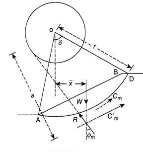
A4) The friction circle method considers the overall moment equilibrium of the wedge of soil using the arc of a circle as the failure surface. Figure 17.17 shows the failure surface of radius r and center O. As the wedge of soil slides along the failure surface, a frictional force is generated along the failure surface.
Let F be the frictional force opposing the movement of the sliding mass acting tangential to the failure surface, N be the normal reaction acting perpendicular to the tangent to the failure surface, and R be the resultant of the frictional force, F and the normal reaction, N.
It is known that the resultant, R, which makes an angle ɸm with the normal to the failure surface. Now, if a small circle is drawn with O as center and r sinɸm as radius, the resultant R will be tangential to this circle. This small circle of radius r sinɸm is known as the friction circle.
Q5) Explain factor of safety?
A5) The factor of safety is commonly thought of as the ratio of the maximum load or stress that a soil can sustain to the actual load or stress that is applied. Referring to Fig. 11.1 the factor of safety F, with respect to strength, may be expressed as follows: F = τ ff τ
where τff is the maximum shear stress that the soil can sustain at the value of normal stress of σn, τ is the actual shear stress applied to the soil. Equation 11.1 may be expressed in a slightly different form as follows: τ = c F + σn tan φ F
Two other factors of safety which are occasionally used are the factor of safety with respect to cohesion, Fc, and the factor of safety with respect to friction, Fφ. The factor of safety with respect to cohesion may be defined as the ratio between the actual cohesion and the cohesion required for stability when the frictional component of strength is fully mobilised. 11-2 This may be expressed as follows: τ = c Fc + σn tan φ
The factor of safety with respect to friction, Fφ, may be defined as the ratio of the tangent of the angle of shearing resistance of the soil to the tangent of the mobilised angle of shearing resistance of the soil when the cohesive component of strength is fully mobilised. One way in which this may be expressed is as follows: τ = c + σn tan φ Fφ
A further factor of safety which is sometimes used is FH, the factor of safety with respect to height.This is defined as the ratio between the maximum height of a slope to the actual height of a slope and may be expressed as follows: FH = Hmax H
The factors of safety Fc, Fφ, FH are only occasionally used in slope stability analyses. The factor of safety with respect to strength (F) as expressed in equation , is the one which is almost universally used in calculations.
Q6) Describe Stability Analysis of Finite Slopes Using the Swedish Circle Method?
A6) Investigations carried out in Sweden on slope failures indicated that the failure surface resembles the arc of a circle. Fellenius developed a method for stability analysis of a slope assuming a circular failure surface, which is known as the Swedish circle method.
Stability Analysis for Cohesive Soil (ɸU = 0 Analysis):
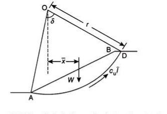
Figure 17.8 shows a slope AB, the stability of which is to be determined. A trial slip surface of radius r is assumed and the factor of safety of the slope is determined for the assumed trial slip surface.
Let r be the radius of slip surface about center O, W be the weight of the soil of the wedge ABDA per m length acting through its centroid, and driving or destabilizing moment –
Factor of safety of the slope along trial slip surface AD is –
The distance of the centroid (x̅) of the wedge ABDA from the center of rotation “O” can be determined by dividing the wedge into a number of vertical slices and dividing the algebraic sum of the moment of weight of each slice about centre “O” by the weight of the wedge.
The analysis is repeated for a number of trial slip surfaces and the factor of safety is determined in each case. The slip surface corresponding to minimum factor of safety is the critical slip surface.
c – ɸ Analysis:
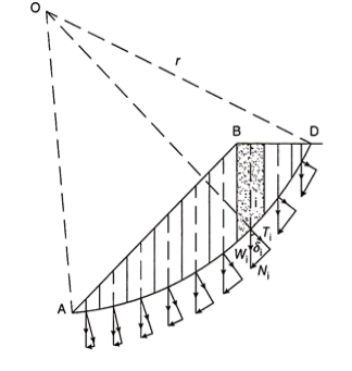
For soil, which has both cohesion and friction components of shear strength, that is, c – ɸ soil, the shear strength along the slip surface is also contributed by the frictional component, which is a function of normal stress. The normal stress varies at every point on the slip surface with the horizontal and hence the analysis is done by dividing the wedge ABDA into a number of vertical slices, as shown in Fig. 17.9. The force between the slices is neglected and each slice is assumed to act independently as a column of soil.
The weight Wi of each slice is assumed to act at its center. If this weight is resolved into normal (Ni) and tangential components (Ti, the normal component, Ni will pass through the center of rotation “O” and does not cause any moment. However, the tangential component, Ti, will cause a driving moment MDi = Ti. r, where r is the radius of the slip surface. The tangential components of a few slices at the base may cause resisting moment, in which case Ti for those slices is considered negative.
As per Coulomb’s equation,
Resisting force along the slip surface = (c.Δl + Ni tan ɸ)
Where c is the unit cohesion and Δl is the length of the base of each slice = b. secα
Analysis of finite and infinite slopes
Infinite Slopes in Dry Cohesionless Soils:
A typical section or “slice” through the potential failure zone of a slope in a dry cohesionless soil, e.g., dry sand, is shown in Figure 6-3, along with its free body diagram. The weight of the slice of width b and height h having a unit dimension into the page is given by:

where γ is the effective unit weight of the dry soil. For a slope with angle β as shown in Figure below:
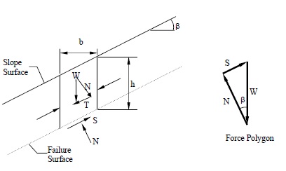
The normal (N) and tangential (T) force components of W are determined as follows:


The available shear strength along the failure plane is given by:

The factor of safety (FS) is defined as the ratio of available shear strength to strength required to maintain stability. Thus, the FS will be given by:

For an infinite slope analysis, the FS is independent of the slope depth, h, and depends only on the angle of internal friction, φ, and the angle of the slope, β. The slope is said to have reached limit equilibrium when FS=1.0. Also, at a FS = 1.0, the maximum slope angle will be limited to the angle of internal friction, φ.
Infinite Slopes in c-φ Soils with Parallel Seepage:
If a saturated slope in a c-φ soil has seepage parallel to the surface of the slope as shown in Figure below, the same limit equilibrium concepts may be applied to determine the FS, which will now depend on the effective normal force (N'). In the following analysis, effective shear strength parameters, c' and φ' are used.
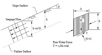
From Figure above, the pore water force acting on the base of a typical slice having a unit dimension into the page is:

where h is any depth less than or equal to the depth of saturation and b is a unit width.
The available frictional strength, S, along the failure plane will depend on φ' and the effective normal force, N' =N-U, where N is the total normal force. The equation for S is:

The factor of safety for this case will be:

By substituting W = γsat b h into the above expression and rearranging terms, the FS is given by:

where γ' = (γsat - γw).
For c' = 0, the above expression may be simplified to:

From Equation above it is apparent that for a cohesionless material with parallel seepage, the FS is also independent of the slope depth, h, just as it is for a dry cohesionless material as given earlier. The difference is that the FS for the dry material is reduced by the factor γ'/γsat for saturated cohesionless materials to account for the effect of seepage. For typical soils, this reduction will be about 50 percent in comparison to dry slopes.
The above analysis can be generalized if the seepage line is assumed to be located at a normalized height, m, above the failure surface where m =z/h. In this case, the FS is:
![FS=frac{c'+hcos^2eta[(1-m)gamma_m+mgamma']tanphi'}{hsineta coseta [(1-m)gamma_m+mgamma_{sat}]}](https://glossaread-contain.s3.ap-south-1.amazonaws.com/epub/1642795817_2227962.png)
and γsat and γm are the saturated and moist unit weights of the soil below and above the seepage line. The above equation may be readily reformulated to determine the critical depth of the failure surface in a c'-φ' soil for any seepage condition.
Q7) Explain Friction Circle Method:
A7) The friction circle method considers the overall moment equilibrium of the wedge of soil using the arc of a circle as the failure surface. Figure 17.17 shows the failure surface of radius r and center O. As the wedge of soil slides along the failure surface, a frictional force is generated along the failure surface.
Let F be the frictional force opposing the movement of the sliding mass acting tangential to the failure surface, N be the normal reaction acting perpendicular to the tangent to the failure surface, and R be the resultant of the frictional force, F and the normal reaction, N.
It is known that the resultant, R, which makes an angle ɸm with the normal to the failure surface. Now, if a small circle is drawn with O as center and r sinɸm as radius, the resultant R will be tangential to this circle. This small circle of radius r sinɸm is known as the friction circle.
Q8) Forces Acting on the Sliding Mass:
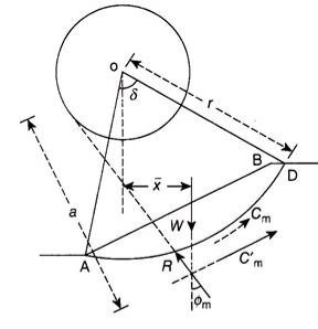
A8) The following are the forces acting on the wedge of the sliding mass:
1. W is the weight of sliding mass. It acts vertically downwards through the centroid of the wedge of sliding mass.
2. The resultant (of F and N) R acting tangential to the friction circle.
3. The cohesive force Cm acting along the curved failure surface at a radial distance r.
Thus, the sliding mass is in equilibrium under the action of only three forces W, Cm, and R. It is known from the principles of mechanics that when a body is in equilibrium under the action of three forces, the three forces are concurrent.
Thus, in the friction circle method, the factor of safety is determined by considering the equilibrium of the sliding mass, subjected to the three concurrent forces W, Cm, and R.
Q9) Determination of Factor of Safety:
A9) Following is the procedure to determine the factor of safety using the friction circle method:
Q1. A trial value of factor of safety with respect to friction, Fɸ, is assumed and the mobilized friction angle (ɸm) is determined from –
tanɸm= tanɸ/Fɸ…(17.36)
2. The slope AB of height H and the trial slip surface of radius r with O as center are constructed to some scale. The friction circle is constructed with O as center and r sinɸm as radius.
3. A vertical line is drawn through the centroid of the sliding wedge ABDA, representing the line of action of W, to intersect the trial slip surface at point E.
4. A tangent ET is drawn to the friction circle from point E. The line ET gives the direction of R
5. The weight of the sliding wedge of soil mass is determined from –
W = γ.A.1 = γ. A …(17.37)
where A is the area of the wedge of soil ABDA and γ the bulk density of the soil.
6. The force diagram is now constructed by drawing vertical line, ab, representing W to some scale. A line is drawn, representing the direction of C’m, from point a parallel to the slope AB. Another line is drawn, representing the direction of R, from point b parallel to the line ET. These two lines intersect at point c, completing the force diagram abc.
7. The length of the line ac is measured, which gives the force C’m, to the scale of the force diagram. The mobilized cohesion is computed from –
cm = C’m,/lc …(17.38)
8. The factor of safety with respect to cohesion (Fc) is computed from –
Fc = c/cm …(17.39)
9. The value of Fc computed from Eq. (17.39) is compared with the assumed value of Fɸ. If they do not agree, the procedure is repeated from steps 1 to 8, by assuming another value of Fɸ. The solution is found to be convergent, so that it is useful to use the value of Fc computed in a given trial as Fɸ in the next trial. It was found that three to four trials are sufficient to obtain a reasonably accurate value of Fc = Fɸ.
10. The final value of the factor of safety obtained in step 9 is applicable for the assumed trial slip surface. The procedure is repeated from steps 1 to 9, by using a number of possible trial slip surfaces with different radius and center.
11. The minimum value of factor safety obtained in step 10 is taken as the factor of safety for the slope and the corresponding slip surface is taken as the critical
Q10) Explain Stability numbers and charts?
A10) To find the stability of slope with the possible greatest angle of slope and angle of internal friction. This method represents the result using a theoretical number, which is called the stability number.
Analyses of stability of slopes with irregular inclination or with heterogeneous soils require the application of now computerized methods. However, charts for homogeneous slopes with a well-defined inclination are often used in practice as a quick reference, and they are a convenient tool for the first estimate of the slope safety. An early example of such charts is the one produced by Taylor ~1937!. Taylor used the friction circle method ~w-circle method! to arrive at his chart. To present the results in a dimensionless manner he introduced a stability number defined as N5 cd gH 5 c gHF (2) where g5unit weight of soil and H5slope height.
The stability number in Eq. Represents the combination of c, g, and H, which guarantees the slope to be at the verge of failure ~limit equilibrium! For given slope inclination angle b and internal friction angle of the soil w. The stability number for w50 becomes independent of the slope inclination when b is less than about 50°. This is an artifact of problem formulation with infinite soil depth, not just in the kinematic approach of limit analysis, but also in more approximate limit equilibrium techniques. This can be explained easily following limit analysis formulation.
When w50 the failure surface becomes cylindrical @Fig. 2~b!#, and the dimensions of the most adverse failure mechanism ~for b less than about 50°! Tend to infinity. Thus slope height H becomes negligible with respect to failure surface radius r.
