Unit-4
Soil exploration
Q1) What is soil investigation?
A1) Soil Investigation or geotechnical investigation is a procedure that determines the stratigraphy (study of rocks) and relevant physical properties of the soil underlying the site. This is done to ensure that this substructure, which is eventually going to hold up homes, is safe and enduring.
Soil investigation is an integral part of the construction process which is done to obtain information about the physical characteristics of soil/rock around a site. It is a below-ground investigation wherein the soil strata is sampled and tested to establish its characteristics, which will influence the construction project.
Objective of soil exploration
Stages in Site Investigation
Site investigation or sub-soil exploration is carried out stage-wise as given below.
3. Detailed exploration
4. Preparation of soil investigation report
Site reconnaissance Site reconnaissance is the first stage of site investigation. In this stage, visual inspection of the site is done and information about topographical and geological features of the site are collected. The general observations made in site reconnaissance are as follows:
Preliminary site exploration
The soil sample is collected from experimental borings and shallow test pits and simple laboratory tests such as moisture content test, density, unconfined compressive strength test, etc. are conducted. Simple field tests such as penetration methods, sounding methods, geophysical methods are performed to get the relative density of soils, strength properties, etc.
Detailed soil exploration
In this stage, numerous field tests such as in-situ vane shear test, plate load test, etc. and laboratory tests such as permeability tests, compressive strength test on undistracted soil samples are conducted to get exact values of soil properties.
Preparation of soil investigation report
A sub-soil investigation or exploration report generally has the following sections :
Q2) What are the different methods f soil exploration?
A2)
12. Direct: test pits, trial pits or trenches
13. Semi-direct: Boring
14. Indirect: Soundings or penetration tests and geophysical methods
15. Direct methods -Test pits
16. Test pits or trenches are an open type or accessible soil exploratory system.
17. Soils can be examined in their natural condition.
18. Sampling procedures can collect the underlying soils samples and used for finding strength and other engineering properties by relevant laboratory tests.
19. Test pits are considered fit only for small depths up to 3m; the cost of these increases quickly with depth.
20. For greater depths, parallel supports or bracing of the excavations will be needed.
21. Test pits are typically made only for improving other methods or for minor structures.
22. Semi-direct methods – boring:
23. a) Boring: Making or drilling boreholes into the ground with an outlook to obtaining soil or rock samples from particularized or known depths is known as boring.
Inspection
The first step in this connection is the inspection of the site and its vicinity to get a preliminary idea of the site conditions. This includes the study of the existing buildings in the neighborhood and if possible the type of their foundations. The cuts made in the nearby areas should also be looked into. The subject can be discussed with those persons who were associated in constructing buildings in the surroundings with regard to their experiences and difficulties encountered by them.
Test Pits
Test pits are dug by hand or by excavating machines. The size of the pit should be such that a person can easily enter the pit and have a visual inspection. Both disturbed and undisturbed soil samples are collected from the pit for detailed analysis
Probing
This will give a rough idea of the underlying soil. In this, a steel bar of 25 to 40 mm (1 inch to 1.5 inch) in diameter is driven into the ground until a hard stratum is met with. The bar is driven by a hammer. The bar is then drawn out at intervals and the soil sticking to the bar is examined to get an idea of the type of thesoil. An experienced workman can assess the nature of the soil by observing the way the rod is penetrated into the soil.
Q3) Define boring?
A3) In this process, bore holes are made in the ground and the soil samples collected. Boring helps in obtaining 1) extent of each strata of soil/rock 2) nature of each stratum and the engineering properties of the soils 3) location of ground water table. The depth and number of boreholes will depend upon the type of the structure and nature of the soil as obtained from preliminary examination. The depth of boreholes is governed by the depth of the soil affected by the loading. As a rough estimate, it is advisable to investigate the subsoil to a depth of at least twice the width of the anticipated largest size of the foundation. In case of a pile foundation, the depth of boring should extend into the bearing stratum.
Q4) What are the different types of boring method?
A4)
Displacement boring
It is combined method of sampling & boring operation. Closed bottom sampler, slit cup, or piston type is forced in to the ground up to the desired depth. Then the sampler is detached from soil below it, by rotating the piston, & finally the piston is released or withdrawn. The sampler is then again forced further down & sample is taken. After withdrawal of sampler & removal of sample from sampler, the sampler is kept in closed condition & again used for another depth.
Features
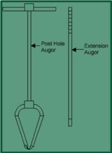
Auger Boring
Rotary drilling
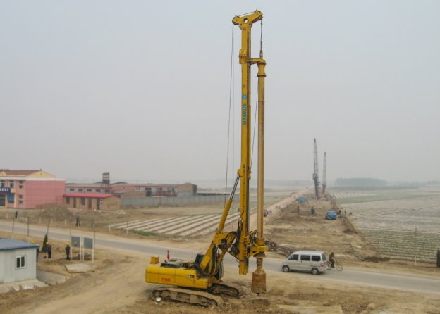
Rotary drilling method of boring is suitable for all types of soil including rocks. It is used to take disturbed as well as undisturbed soil sample. So, it is specifically applicable for stiff soil layers. The practical depth of sampling is around 70m and greater depth based on the type of utilized equipment.
Generally, thin-walled tube samplers and various piston samplers are used to collect undisturbed soil specimen. The diameter of the undisturbed soil sample is around 100 mm and ranges from 150mm to 200mm for rocks.
ROTARY DRILLING
Wash boring
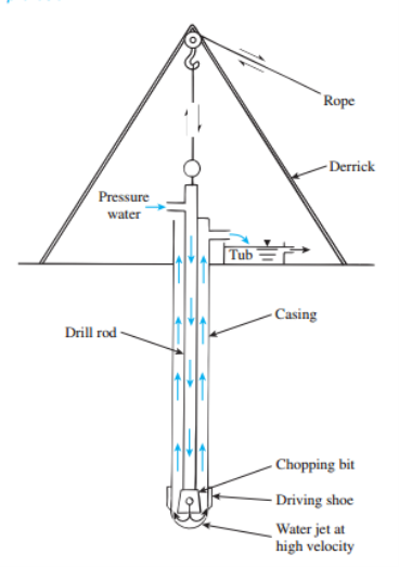
Wash boring method is used to collect disturbed and undisturbed samples in almost all types of soils except rocks. In this technique, portable, cheap, and limited equipment is used which is an advantage of wash boring. Similar to rotary drilling, thin-walled tube samplers and piston samplers are used to recover undisturbed soil samples with minimum 50 mm diameter and maximum 100 mm diameter.
WASH BORING
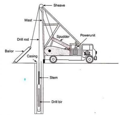
Percussion drilling
It is used for all types of soils and rocks including stiff soils and rocks. Percussion drilling is used to take disturbed and undisturbed specimen but the quality of undisturbed samples is not that good because of the heavy blows of the chisel.
Similar to rotary drilling and wash boring, the soil specimen can be taken from a depth of 70m and more based on the utilized equipment. The diameter of disturbed soil samples is about 100 mm and greater, and obtaining smaller diameter samples would be uneconomical.
Continuous sampling
The sampling operation advances the borehole and the boring is accomplished entirely by taking samples continuously. The casing is used to prevent the caving in soils. It provides more reliable and detail information on soil condition than the other methods. Therefore, it is used extensively in detailed and special foundation exploration for important structures.
It is slower method and more expensive than intermittent sampling. When modern rotary drilling rigs or power-driven augers are not available, continuous sampling may be used to advantage for advancing larger diameter borings in stiff and tough strata of clay and mixed soil.
In the Boston district, corps of Engineers has made faster progress and reduced cost by use of continuous sampling in advancing 3-inch diameter borings through compact gravelly glacial till, which is difficult to penetrate by any boring method.
Q5) Explain Soil sampler and its procedure?
A5)
The basic tool used for the collection of undisturbed soil samples from test pits or boreholes at required depth is known as a soil sampler.
The fundamental requirement of a sampling tool is that when it is forced into the ground, it should cause as little displacement, remolding, and disturbance to the soil as possible.
Soil Sampling Equipment List
Stainless-steel spoon Trier Scoop Trowel 3 TITLE: SOIL SAMPLING CATEGORY: ENV 3.13 REVISED: August 1997 Spatula Stainless-steel tulip bulb planter Spade or shovel Vehimeyer soil sampler outfit - tubes - points - drive head - drop hammer - fuller jack and grip Soil-coring device Thin-walled tube sampler Split-spoon sampler Shelby tube sampler Laskey sampler Bucket auger Hand-operated power auger Continuous-flight auger Dutch auger Eijkelcamp stoney soil auger Backhoe Hand auger with replaceable sleeves
The following design features of the sampling tool control the degree of disturbance:
1. Cutting edge.
2. Inside-wall friction.
3. Non-return valve.
4. Recovery ratio.
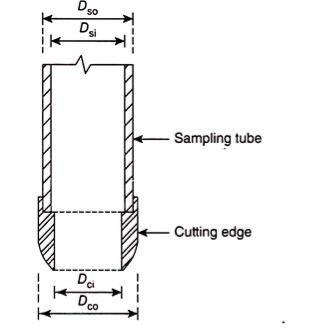
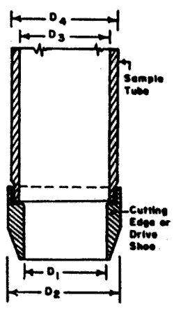
Cutting edge is the beveled and sharp edge at the bottom of the soil sampler. It may be an integral part of the soil sampler or a separate cutting bit may be screwed to the bottom of the sampler. It mainly facilitates driving of the soil sampler through the soil.
A typical cutting edge shown in Fig. should have the following design features:
The internal diameter of the cutting edge (Dci) should be slightly less than the internal diameter of the sampling tube (Dsi) to give inside clearance (Ci) (see Fig.).
The inside clearance does the following:
a. Allows for elastic expansion of the soil as it enters the sampler.
b. Reduces the frictional drag on the soil sample from the wall of the sampler, which otherwise causes disturbance to the sample.
c. Helps to retain the soil sample.
Inside clearance is given by –
where Dsi is
the inside diameter of the sampling tube and Dci is the inside diameter of the cutting edge.
Outside Clearance:
Outside clearance (Co) is the gap between the outer surface of the cutting edge and the outside surface of the sampling tube. Outside clearance prevents frictional drag between the outside surface of the sampling tube and the walls of the borehole or and hence facilitates easy driving and withdrawal of the sampler and also prevents damage of the sampler. The outside diameter of the cutting edge should be slightly more than that of the sampling tube to get the outside clearance.
Outside clearance is, therefore, defined by –
where Dco is the outside diameter of the cutting edge and Dso is the outside diameter of the sampling tube. The outside clearance should not be much greater than the inside clearance.
The outside clearance, the wall thickness of the sampler, and the inside clearance together influence the displacement caused to the natural soil during collection of the soil sample. The more the sum of these three, the greater will be the soil displacement and the more will be the degree of disturbance caused to the soil sample. This is expressed in the form of area ratio (Ar) and is defined as –
The area ratio should be kept as low as possible, consistent with the strength requirements of the sampling tube as well as the inside and the outside clearance requirements. Its value should not be greater than 20% for stiff formations and 10% for soft sensitive clays. Where it is not possible to provide sufficient inside clearance, piston sampler should be preferably used.
Friction:
The inside-wall friction should be minimized for minimizing the disturbance of the sample by the following actions:
i. Provide suitable inside clearance.
ii. Provide a smooth finish to the sampling tube.
iii. Oil the inside surface of the sampling tube properly.
Non-Return Valve:
The valve should have a large orifice to allow air and water to escape quickly and easily when driving the sampler.
It is defined as the ratio of length of the sample within the sampling tube to the depth of penetration of the sampler during sampling. Thus, recovery ratio (Rr) is expressed by –
Rr = L/H …(14.4)
Where L is the length of the sample within the tube and H is the depth of penetration of the sampling tube.
For satisfactory undisturbed sampling, when excess soil is prevented from entering the tube, the recovery ratio should be between 96% and 98%.
Soil samples are divided into two main categories, undisturbed and disturbed.
Undisturbed samples, which are required mainly for shear strength and consolidation tests, are obtained by techniques which aim at preserving the in-situ structure and water content of the soil. In boreholes, undisturbed samples can be obtained by withdrawing the boring tools (except when hollow-stem continuous-flight augers are used) and driving or pushing a sample tube into the soil at the bottom of the hole.
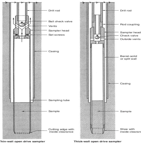
completely filled so that there is negligible air space above the sample. All samples should be clearly labelled to show the project name, date, location, borehole number, depth and method of sampling; in addition, each sample should be given a serial number. Special care is required in the handling, transportation and storage of samples (particularly undisturbed samples) prior to testing. The sampling method used should be related to the quality of sample required. Quality can be classified as follows, according to the uses to which the sample can be put: Class 1: classification, water content, density, shear strength, deformation and consolidation tests. Class 2: classification, water content and density tests. Class 3: classification and water content tests. Class 4: classification tests only. Class 5: strata identification only. For Classes 1 and 2 the sample must be undisturbed. Samples of Classes 3, 4 and 5 may be disturbed. The principal types of tube samplers are described below. Open drive sampler An open drive sampler (Figure 10.5(a)) consists of a long steel tube with a screw thread at each end.
Q6) What are the difffrent types of sampler?
A6)
Open drive sampler
An open drive sampler (Figure 10.5(a)) consists of a long steel tube with a screw thread at each end. A cutting shoe is attached to one end of the tube. The other end of 382 Ground investigation the tube screws into a sampler head to which, in turn, the boring rods are connected. The sampler head also incorporates a non-return valve to allow air and water to escape as the soil fills the tube and to help retain the sample as the tube is withdrawn. The inside of the tube should have a smooth surface and must be maintained in a clean condition. The internal diameter of the cutting edge (dc) should be approximately 1% smaller than that of the tube to reduce frictional resistance between the tube and the sample. This size difference also allows for slight elastic expansion of the sample on entering the tube and assists in sample retention. The external diameter of the cutting shoe (dw) should be slightly greater than that of the tube tube to reduce the force required to withdraw
OPEN DRIVE SAMPLER
Figure (a) Open drive sampler, (b) thin-walled sampler, (c) split-barrel sampler and (d) stationary piston sampler. Sampling 383the tube. The volume of soil displaced by the sampler as a proportion of the sample volume is represented by the area ratio (Ca) of the sampler, where Ca ¼ d2 w d2 c d2 c ð10:1Þ The area ratio is generally expressed as a percentage. Other factors being equal, the lower the area ratio, the lower the degree of sample disturbance. The sampler can be driven dynamically by means of a drop weight or sliding hammer, or statically by hydraulic or mechanical jacking. Prior to sampling all loose soil should be removed from the bottom of the borehole. Care should be taken to ensure that the
sampler is not driven beyond its capacity, otherwise the sample will be compressed against the sampler head. Some types of sampler head have an overdrive space below the valve to reduce the risk of sample damage. After withdrawal, the cutting shoe and sampler head are detached and the ends of the sample are sealed. The most widely used sample tube has an internal diameter of 100 mm and a length of 450 mm: the area ratio is approximately 30%. This sampler is suitable for all clay soils. When used to obtain samples of sand, a core-catcher, a short length of tube with spring-loaded flaps, should be fitted between the tube and cutting shoe to prevent loss of soil.
Thin-walled sampler
Thin-walled samplers (Figure 10.5(b)) are used in soils which are sensitive to disturbance such as soft to firm clays and plastic silts. The sampler does not employ a separate cutting shoe, the lower end of the tube itself being machined to form a cutting edge. The internal diameter may range from 35 to 100 mm. The area ratio is approximately 10% and samples of first-class quality can be obtained provided the soil has not been disturbed in advancing the borehole. In trial pits and shallow boreholes the tube can often be driven manually.
Split-barrel sampler
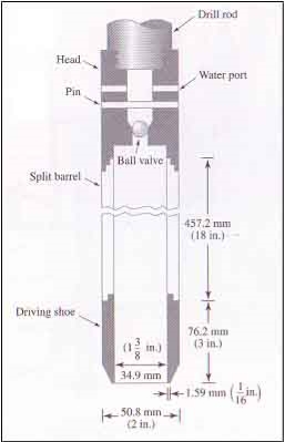
Split-barrel samplers (Figure 10.5(c)) consist of a tube which is split longitudinally into two halves: a shoe and a sampler head incorporating air-release holes are screwed onto the ends. The two halves of the tube can be separated when the shoe and head are detached to allow the sample to be removed. The internal and external diameters are 35 and 50 mm, respectively, the area ratio being approximately 100%, with the result that there is considerable disturbance of the sample (Class 3 or 4). This sampler is used mainly in sands, being the tool specified in the standard penetration test
Stationary piston sampler
Stationary piston samplers (Figure 10.5(d)) consist of a thin-walled tube fitted with a piston. The piston is attached to a long rod which passes through the sampler head and runs inside the hollow boring rods. The sampler is lowered into the borehole with the 384 Ground investigation piston located at the lower end of the tube, the tube and piston being locked together by means of a clamping device at the top of the rods. The piston prevents water or loose soil from entering the tube. In soft soils the sampler can be pushed below the bottom of the borehole, bypassing any disturbed soil. The piston is held against the soil (generally by clamping the piston rod to the casing) and the tube is pushed past the piston (until the sampler head meets the top of the piston) to obtain the sample. The sampler is then withdrawn, a locking device in the sampler head holding the piston at the top of the tube as this takes place. The vacuum between the piston and the sample helps to retain the soil in the tube: the piston thus serves as a non-return valve. Piston.
At the top of the tube as this takes place. The vacuum between the piston and the sample helps to retain the soil in the tube: the piston thus serves as a non-return valve. Piston samplers should always be pushed down by hydraulic or mechanical jacking: they should never be driven. The diameter of the sampler is usually between 35 and 100 mm but can be as large as 250 mm. The samplers are generally used for soft clays and can produce samples of first-class quality up to 1 m in length.
Continuous sampler
The continuous sampler is a highly specialized type of sampler which is capable of obtaining undisturbed samples up to 25 m in length: the sampler is used mainly in soft clays. Details of the soil fabric can be determined more easily if a continuous sample is available. An essential requirement of continuous samplers is the elimination of frictional resistance between the sample and the inside of the sampler tube. In one type of sampler, developed in Sweden [7], this is achieved by superimposing thin strips of metal foil between the sample and the tube. The lower end of the sampler has a sharp cutting edge above which the external diameter is enlarged to enable 16 rolls of foil to be housed in recesses within the wall of the sampler.
The ends of the foil are attached to a piston which fits loosely inside the sampler: the piston is supported on a cable which is fixed at the surface. Lengths of sample tube (68 mm in diameter) are attached as required to the upper end of the sampler. As the sampler is pushed into the soil the foil unrolls and encases the sample, the piston being held at a constant level by means of the cable. As the sampler is withdrawn the lengths of tube are uncoupled and a cut is made, between adjacent tubes, through the foil and sample. Sample quality is generally Class 1 or 2. Another type is the Delft continuous sampler, of either 29 or 66 mm in diameter. The sample feeds into an impervious nylon stockinet sleeve. The sleeved sample, in turn, is fed into a fluid-supported thin-walled plastic tube.
Compressed air sampler
The compressed air sampler (Figure 10.7) is used to obtain undisturbed samples of sand (generally Class 2) below the water table. The sample tube, usually 60 mm in diameter, is attached to a sampler head having a relief valve which can be closed by a rubber diaphragm. Attached to the sampler head is a hollow guide rod surmounted by a guide head. An outer tube, or bell, surrounds the sample tube, the bell being attached to a weight which slides on the guide rod. The boring rods fit loosely into a plain socket in the top of the guide head, the weight of the bell and sampler being supported by means of a shackle which hooks over a peg in the lower length of boring rod: a light cable, leading to the surface, is fixed to the shackle. Compressed air, produced by a foot Sampling 385pump, is supplied through a tube leading to the guide head, the air passing down the hollow guide rod to the bell. The sampler is lowered on the boring rods to the bottom of the borehole, which will contain water below the level of the water table. When the sampler comes to rest at the bottom of the borehole the shackle springs off the peg, removing the connection between the sampler and the boring rods. The tube is pushed into the soil by means of the boring rods, a stop on the guide rod preventing overdriving: the boring rods are then withdrawn.
Compressed air is now introduced to expel the water from the bell and to close the valve in the sampler head by pressing the diaphragm downwards. The Figure 10.6 Continuous sampler. 386 Ground investigation tube is withdrawn into the bell by means of the cable and then the tube and bell together are raised to the surface. The sand sample remains in the tube by virtue of arching and the slight negative pore water pressure in the soil. A plug is placed at the bottom of the tube before the suction is released and the tube is removed from the sampler head.Window sampler
This sampler, which is most suited to dry cohesive soils, employs a series of tubes, usually 1 m in length and of different diameters (typically 80, 60, 50 and 36 mm). Tubes Figure 10.7 Compressed air sampler. Sampling 387of the same diameter can be coupled together. A cutting shoe is attached to the end of the bottom tube. The tubes are driven into the soil by percussion using either a manual or rig-supported device and are extracted either manually or by means of the rig. The tube of largest diameter is the first to be driven and extracted with its sample inside.
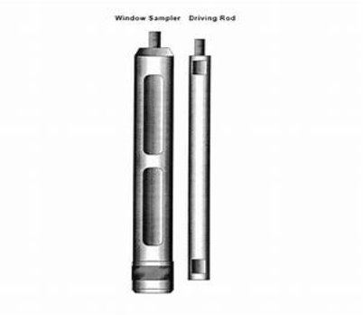
WINDOW SAMPLER
A tube of lesser diameter is then driven below the bottom of the open hole left by extraction of the larger tube. The operation is repeated using tubes of successively lower diameter and depths of up to 8 m can be reached. There are longitudinal slots or ‘windows’ in the walls at one side of the tubes to allow the soil to be examined and enable disturbed samples of Class 3 or 4 to be taken.
Q7) Explain Trial pits?
A7)
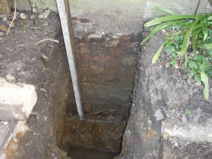
A trial pit (also known as a test pit) is a type of intrusive ground investigation that is used as a means of determining the condition of the ground, typically before beginning construction works.
Trial pits are commonly used to investigate shallow ground conditions to develop an understanding of the profile of soils within the ground. They can be particularly useful where buried structures, variable conditions or contamination is suspected or needs further investigation.
They can be excavated by hand or using a backhoe excavator, generally to a depth of up to 3.5-4.5 m. If a trial pit is deeper than 1.2 m and is intended to be entered by people, it should be made secure against the possibility of structural collapse.
Trial pits (or trenches) can be more cost-effective than boreholes but they cannot reach the same depth. Trial pits can also excavate relatively quickly. However, they can cause significant surface disturbance and it can be difficult to properly fill excavations when the pit is no longer needed.
Q8) Standard Penetration Test
A8)
Standard Penetration Test Tools.
1. Drilling Rig.
2. Split spoon (tube).
3. Drop hammer 65 kg (140 lbs ).
4. Driving head (anvil).
5. Guiding rod.
6. Tripod.
7. Extension rods.
Standard Penetration Test Theory.
The number or blows required for 12 inches penetration resistance of the soil. It is generally referred as the ‘N’ value and measured in blows/unit penetration.
The Standard penetration test ( SPT ) is widely used to get the bearing capacity of soil directly at a certain depth. The consistency of clayey soils can often be estimated from this test.
When a borehole is extended to a predetermined depth, the drill tools are removed, and the sampler (split spoon) is lowered to the bottom of the borehole.
The sampler is driven into the soil, by hammer blows to the top of the drill rod. The standard weight of the hammer is 140 lbs.(62.3 N) the number of blows required for spoon penetration of three “6” inches (15 cm) intervals is recorded.
The number of blows required for the last two intervals are added to give the standard penetration number at that depth.
Standard Penetration Test Procedure:
1. Erect the tripod over the test hole and assemble the unit.
2. Allow the spoon to rest on the bottom of the hole.
3. Drive the spoon with blows from the hammer falling 75 cm (30 inches), until either 45 cm (18 inches) have been penetrated or 100 blows have been applied.
4. Record the number of blows required to effect each 15 cm (6 inches) of penetration. The first 6 inches is considered as seating drive.
5. The number of blows required for the second and third 15 cm (6 inches) of drive added is recorded as the penetration resistance value N of the soil.
Observations and Calculations:
Result:
The penetration resistance value, N of the soil is _________________blow .
Formula: q= 3.5 (N-3) [B+0.3/2B]Rw2Rd.
Where.
q= Allowable net pressure in T/m2.
N = Standard penetration number.
B = Breadth of footing in meters.
Rw2 = Water reduction factor= 0.5 [ 1+Z/B] .
Rd = Depth factor = l+D/B C or C= 2.0.
Z = Depth of water table below foundation level.
Precautions:
1. If the test is to be carried out in gravely soils, then the driving shoe is replaced by solid 60-degree cone.
2. Below the water table, care should be taken to avoid entry of water through the bottom of the bore due to loosening of soil happens.
3. Water should be added as necessary to maintain the water table level in the bore hole.
4. If the test is carried out in very fine sand or silty sand below the water table the measured “N” value if greater then 15, should be corrected for the increased resistance excess more water pressure set up during driving and unable to loose immediately.
5. Drilling mud can be sued to support the sides of the hole.
6. Stop dropping weight, when the sample penetrates less than 25 mm under 50 blows.
Q9) What is borehole log?
A9)
After an investigation has been completed and the results of any laboratory tests are available, the ground conditions discovered in each borehole (or trial pit) are summarized in the form of a borehole log. An example of such a log appears in Table 10.1, but details of the layout can vary. The last few columns are originally left without headings to allow for variations in the data presented. The method of investigation and details of the equipment used should be stated on each log. The location, ground level and diameter of the hole should be specified together with details of any casing used. The names of the client and the project should be stated. The log should enable a rapid appraisal of the soil profile to be made. The log is prepared with reference to a vertical scale. A detailed description of each stratum is given and the levels of strata boundaries clearly shown: the level at which boring was terminated should be indicated. The different soil (and rock) types are represented by means of a legend using standard symbols. The depths, or ranges of depth, at which samples were taken or at which in-situ tests were performed are recorded: the type of sample is also specified. The results of certain laboratory or in-situ tests may be given in the log.
The despths at which groundwater was encountered and subsequent changes in levels, with times, should be detailed. The soil description should be based on particle size distribution and plasticity, generally using the rapid procedure in which these characteristics are assessed by means of visual inspection and feel: disturbed samples are generally used for this purpose. The description should
include details of soil colour, particle shape and composition: if possible the geological formation and type of deposit should be given. The structural characteristics of the soil mass should also be described but this requires an examination of undisturbed samples or of the soil in situ (e.g. in a trial pit). Details should be given of the presence and spacing of bedding features, fissures and other relevant characteristics.
Digital Soil Boring Logs for Efficient Data Entry and Documentation
Borehole logs, also called soil boring logs, are important documents that directly influence the safety and quality of planned structures. Though typical borehole logs are documented through paper, going digital presents a number of advantages that help ease the process for geotechnical engineers:
Q10) Explain geophysical method?
A10) Under certain conditions geophysical methods may be useful in ground investigation, especially at the reconnaissance stage. However, the methods are not suitable for all ground conditions and there are limitations to the information that can be obtained: they must be considered mainly as supplementary methods. It is possible to locate strata boundaries only if the physical properties of the adjacent materials are significantly different. It is always necessary to check the results against data obtained by direct methods such as boring. Geophysical methods can produce rapid and economic results, e.g. for the filling in of detail between widely spaced boreholes or to indicate where additional boreholes may be required, provided such correlations are established. The methods can be useful in estimating the depth to bedrock or to the water table. There are several geophysical techniques, based on different physical principles. Two of these techniques are described below.
Q11) Describe Seismic refraction method?
A11) The seismic refraction method depends on the fact that seismic waves have different velocities in different types of soil (or rock); in addition, the waves are refracted when they cross the boundary between different types of soil. The method enables the general soil types and the approximate depths to strata boundaries, or to bedrock, to be determined. Waves are generated either by the detonation of explosives or by striking a metal plate with a large hammer. The equipment consists of one or more sensitive vibration transducers, called geophones, and an extremely accurate time-measuring device called a seismograph.
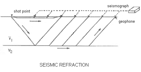
A circuit between the detonator or hammer and the seismograph starts the timing mechanism at the instant of detonation or impact. The geophone is also connected electrically to the seismograph: when the first wave reaches the geophone the timing mechanism stops and the time interval is recorded in milliseconds. When detonation or impact takes place, waves are emitted in every direction. One particular wave, called the direct wave, will travel parallel to the surface in the direction of the geophone. Other waves travel in a downward direction, at various angles to the horizontal, and will be refracted if they pass into a stratum of different seismic velocity. If the seismic velocity of the lower stratum is higher than that of the upper stratum, one particular wave will travel along the top of the lower stratum, parallel to the boundary, as shown in Figure 10.8(a): this wave continually ‘leaks’ energy back to the surface. Energy from this refracted wave can be detected by the geophone. The procedure (Figure 10.8(a)) consists of installing a geophone in turn at a number of points in a straight line, at increasing distances from the source of wave generation.
The length of the line of points should be 3–5 times the required depth of investigation. A series of detonations or impacts are produced and the arrival time of the first wave at each geophone position is recorded in turn. When the distance between the source and the geophone is short, the arrival time will be that of the direct wave. When the distance between the source and the geophone exceeds a certain value (depending on the thickness of the upper stratum) the refracted wave will be the first to be detected by the geophone. This is because the path of the refracted wave, although longer than that of the direct wave, is partly through a stratum of higher seismic velocity. The use of explosives is generally necessary if the source–geophone distance exceeds 30–50 m or if the upper soil stratum is loose. An alternative procedure consists of using a single geophone position and producing a series of detonations or impacts at increasing distances from the geophone.
. The general types of soil or rock can be determined from a knowledge of these velocities. The depth (D) of the boundary between the two strata (provided the thickness of the upper stratum is constant) can be estimated from the formula D ¼ d 2 v2 v1 v2 þ v1 s ð10:2Þ The method can also be used where there are more than two strata and procedures exist for the identification of inclined strata boundaries and vertical discontinuities. The formulae used to estimate the depths of strata boundaries are based on the assumptions that each stratum is homogeneous and isotropic, the boundaries are plane, each stratum is thick enough to produce a change in slope on the time–distance plot and the seismic velocity increases in each successive stratum from the surface downwards. A layer of clay lying below a layer of compact gravel, for example, would not be detected. Figure 10.8 Seismic refraction method. Geophysical methods 391Other difficulties arise if the velocity ranges of adjacent strata overlap, making it difficult to distinguish between them, and if the velocity increases with depth in a particular stratum. It is important that the results are correlated with data from borings.
Electrical resistivity method
The method depends on differences in the electrical resistance of different soil (and rock) types. The flow of current through a soil is mainly due to electrolytic action and therefore depends on the concentration of dissolved salts in the pore water: the mineral particles of a soil are poor conductors of current. The resistivity of a soil therefore decreases as both the water content and the concentration of salts increase. A dense, clean sand above the water table, for example, would exhibit a high resistivity due to its low degree of saturation and the virtual absence of dissolved salts. A saturated clay of high void ratio, on the other hand, would exhibit a low resistivity due to the relative abundance of pore water and the free ions in that water. In its usual form (Figure 10.9(a)) the method involves driving four electrodes into the ground at equal distances (L) apart in a straight line. Current (I), from a battery, flows through the soil between the two outer electrodes, producing an electric field within the soil.
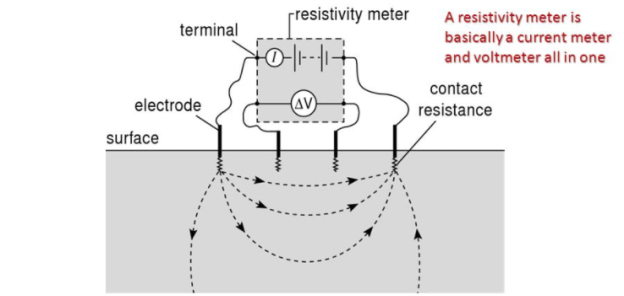
The potential drop (E ) is then measured between the two inner electrodes. The apparent resistivity (R) is given by the equation R ¼ 2 LE I ð10:3Þ The apparent resistivity represents a weighted average of true resistivity in a large volume of soil, the soil close to the surface being more heavily weighted than the soil at depth. The presence of a stratum of soil of high resistivity lying below a stratum of low Figure 10.9 Electrical resistivity method. 392 Ground investigation resistivity forces the current to flow closer to the surface, resulting in a higher voltage drop and hence a higher value of apparent resistivity. The opposite is true if a stratum of low resistivity lies below a stratum of high resistivity. The procedure known as sounding is used when the variation of resistivity with depth is required: this enables rough estimates to be made of the types and depths of strata. A series of readings are taken, the (equal) spacing of the electrodes being increased for each successive reading; however, the centre of the four electrodes remains at a fixed point. As the spacing is increased the apparent resistivity is influenced by a greater depth of soil. If the resistivity increases with increasing electrode spacing it can be concluded that an underlying stratum of higher resistivity is beginning to influence the readings. If increased separation produces decreasing resistivity, on the other hand, a stratum of lower resistivity is beginning to influence the readings. The greater the thickness of a layer, the greater the electrode spacing over which its influence will be observed, and vice versa. Apparent resistivity is plotted against electrode spacing, preferably on log–log paper. Characteristic curves for a two-layer structure are illustrated in Figure 10.9(b). For curve A the resistivity of layer 1 is lower than that of layer 2: for curve B layer 1 has a higher resistivity than layer 2. The curves become asymptotic to lines representing the true resistivities R1 and R2 of the respective layers.
Approximate layer thicknesses can be obtained by comparing the observed curve of resistivity versus electrode spacing with a set of standard curves. Other methods of interpretation have also been developed for two-layer and three-layer systems. The procedure known as profiling is used in the investigation of lateral variation of soil types. A series of readings are taken, the four electrodes being moved laterally as a unit for each successive reading: the electrode spacing remains constant for each reading. Apparent resistivity is plotted against the centre position of the four electrodes, to natural scales: such plots can be used to locate the positions of soil of high or low resistivity. Contours of resistivity can be plotted over a given area. The apparent resistivity for a particular soil or rock type can vary over a wide range of values; in addition, overlap occurs between the ranges for different types. This makes the identification of soil or rock type and the location of strata boundaries extremely uncertain. The presence of irregular features near the surface and of stray potentials can also cause difficulties in interpretation. It is essential, therefore, that the results obtained are correlated with borehole data.
