Unit-5
Earth pressure
Q1) What are the application of soil mechanics in laterally earth pressure?
A1) Horizontal stress (σh) is linearly proportional to depth and is a multiple of vertical stress (σv) as shown in. Eq. 4-1. Eq.
σ h = σ v K = γ h K P = 1 2 σ h h
4-1 Eq. 4-2 Depending on the wall movement, the coefficient K represents active (Ka), passive (Kp) or at-rest (Ko) earth pressure coefficient in the above equation. The resultant lateral earth load, P, which is equal to the area of the load diagram, shall be assumed to act at a height of h/3 above the base of the wall, where h is the height of the pressure surface, measured from the surface of the ground to the base of the wall. P is the force that causes bending, sliding and overturning in the wall.
Depending on the shoring system the value of the active and/or passive pressure can be determined using either the Rankine, Coulomb, Log Spiral and Trial Wedge methods. The state of the active and passive earth pressure depends on the expansion or compression transformation of the backfill from elastic state to state of plastic equilibrium. The concept of the active and passive earth pressure theory can be explained using a continuous dead man near the ground surface for the stability of a sheet pile wall as shown in Figure 4-4. As a result of wall deflection, ∆, the tie rod is pulled until the active and passive wedges are formed behind and in front of the dead man. Element P, in the front of the dead man and element A, at the front of the dead man are acted on by two principal stresses, a vertical stress (σv) and horizontal stress (σh). In the active case, the horizontal stress (σas) is the minor principal stress and the vertical stress (σv) is the major principal stress. In the passive case, the horizontal stress (σp) is the major principal stress and the vertical stress (σv) is the minor principal stress
Q2) Describe Rankine theory ?
A2)
Rankine (1857) considered the equilibrium of a soil element at any depth (h) in the backfill behind a retaining wall and determined the active earth pressure.
Rankine assumed that the soil element is subjected to only two types of stresses:
i. Vertical stress (σz) due to the weight of the soil above the element.
ii. Lateral earth pressure (pa).
Dry Cohesionless Backfill:
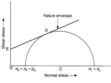
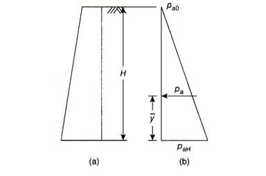
Assuming the back of the wall as smooth and vertical, Rankine considered that the active earth pressure (pa) acts horizontally for a backfill with a horizontal surface [Fig. 15.7(a)]. In the active case, the vertical stress is more than the horizontal stress. Since both the stresses are considered as principal stresses –
Major principal stress, σ1 = σz = γh and minor principal stress, σ3 = pa
Figure 15.6 shows the Mohr’s circle of stresses and the failure envelope for the active case. When the soil element reaches the state of plastic equilibrium with sufficient movement of the wall away from the backfill, the Mohr’s circle of stresses touches the Coulomb’s failure envelope, as shown in Fig. 15.6.
It is known that the principal stresses are related to the shear parameters of the backfill material by the Bell’s equation as follows –
σ1 = σ3 tan2 α + 2c tan α…(15.7)
Considering a dry cohesionless backfill, we have c = 0, hence –
σ1 = σz = γh (in active case) and σ3 = pa
ADVERTISEMENTS:
Substituting these values in Eq. (15.7), we have –
where Ka is the Rankine’s coefficient of active earth pressure and is given by –
α = 45+ ɸ/2
Equation (15.8) indicates that the active earth pressure is zero at the top surface of the backfill (h = 0) and increases linearly with depth below the surface. The distribution of active earth pressure is shown in Fig. 15.7(b).
The total or resultant active earth pressure exerted on the wall is obtained by computing the area of the pressure diagram.
Total active earth pressure = Area of the pressure diagram
that is,
The total active earth pressure acts horizontally through the centroid of the pressure diagram. Vertical distance of total active earth pressure above the base of the wall = y̅.
For a triangular pressure distribution, we know that y̅ = (H/3) above the base of the wall. The failure plane makes an angle of α = 45 + (ɸ/2) with the major principal plane. As the major principal stress in the active case is vertical, the major principal plane is horizontal and the failure plane makes an angle of α = 45 + (ɸ/2) with the horizontal.
Q3) EXPLAIN coulombs theory of earth pressure?
A3) Coulomb’s concept states that the entire lateral earth strain is the same as the response exerted via way of means of the keeping wall while the wedge of soil has a tendency to slip and acts at an attitude eight with the ordinary to the again of the wall.
Q5) What is Retaining wall
A5)
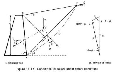
Earlier retaining wall structures were rigid retaining wall, which provides stability by its heavy mass. Charles Augustine de Coulomb (1776) [1] developed a method to calculate earth pressure in which he consider the soil behind wall is whole instead of as an element in soil & it is therefore reasonable to assume that if the wall moved forward slightly a rupture plane would develop somewhere between the wall and backfill. On the course of experiments, he found curved failure plane but he considered straight failure plane for mathematical simplicity. The triangular mass of soil between this plane of failure and the back of wall is referred to as sliding wedge. The limiting equilibrium of the sliding wedge, which formed when the movement of the retaining wall takes place. In active state, the sliding wedge moves downwards as shown in figure 2 and in passive state the sliding wedge moves upwards on slip surface relative to intact backfill, in fact a force of reaction, which it has to exert to keep the sliding wedge in limiting equilibrium. The lateral pressure on wall is equal and opposite to reactive force exerted by wall in order to keep sliding wedge in limiting equilibrium. As shown in figure-2 and figure-3, the gravity retaining wall of height ‘H’, the back face of wall is inclined at angle and backfill is inclined at angle ‘ ’. In active and passive state, the triangular failure wedge of soil along slip plane of weight (W) will exert pressure on wall and rest of backfill soil apart from it. The triangular failure wedge of soil must have two reactions and by applying sine rule over there as shown in figure, the formula for pressure on wall would derived in active and passive state. This analysis is type of limiting equilibrium method. Coulomb assumed soil is dry, homogeneous, cohesionless, isotropic and ideally plastic material. The wall is rough so the resultant pressure will inclined at angle , it is angle of friction between wall and backfill and generally taken as ( ) . Figure 2 Coulomb’s active state of wall Figure 3 Coulombs passive state of wall The sliding wedge itself act as a rigid body & the value of the earth pressure is obtained by considering limiting equilibrium of sliding wedge as a whole. The major drawback of coulomb’s method, it does not give point of application of earth pressure. P. A. Yadav, A. H. Padade, P. P. Dahale and V. M. Meshram http://www.iaeme.com/IJCIET/inCoulomb has derived formula for active state and passive state of retaining wall listed below Coefficient of lateral active earth pressure = * √ + Active earth pressure = Coefficient of lateral passive earth pressure = * √ + Passive earth pressure = William john Macquorn Rankine (1857)[2] proposed to calculate lateral earth pressure on retaining wall by making assumption about the stress condition dex.asp 525 editor@iaeme.com Coulomb has determine .
Q6) What is Sheet pile?
A6)
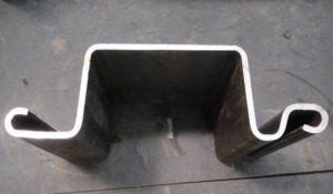
Sheet piles walls are retaining walls constructed to retain earth, water or any other filling materials. These walls are thinner in section compared to masonry walls. Sheet pile walls are generally used for following:
Sheet pile walls can be of timber, reinforced concrete or steel.
Steel sheet piles are most commonly used. Steel sheet piles possess several advantages over other piles. They are:
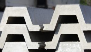
Reinforced concrete sheet piles are precast concrete members, usually with a tongue and groove joints. Typical section of the RCC sheet pile is shown in figure below. These piles are relatively heavy and bulky. They displace large volumes of solid during driving. This large volume displacement of soil tends to increase the driving resistance. Due to this reason, suitable reinforcement is provided considering large driving stresses.
Sheet piles are often connected together in pairs and installed using one of three methods:
Steel sheet piling is the most common because of several advantages over other materials:
Sheet pile wall disadvantages are:
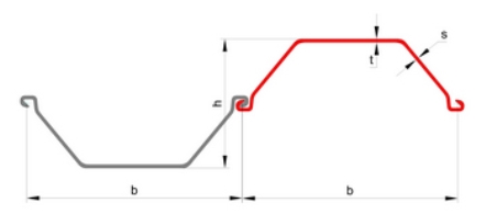
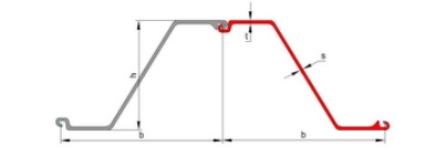
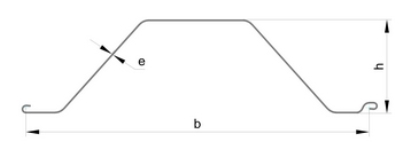
Q7) Different shape of Shapes of Sheet Pile?
A7)


a cut or cutting is where soil or rock from a relative rise along a route is removed. The term is also used in river management to speed a waterway's flow by short-cutting a meander.
Cuts are typically used in road, rail, and canal construction to reduce the length and grade of a route. Cut and fill construction uses the spoils from cuts to fill in defiles to cost-effectively create relatively straight routes at steady grades.
Cuts are used as alternatives to indirect routes, embankments, or viaducts. They also have the advantage of comparatively lower types of cut.
There are at least two types of cut, sidehill cut and through cut. The former permits passage of a transportation route alongside of, or around a hill, where the slope is transverse to the roadway or the railway. A sidehill cut can be formed by means of side casting, i.e., cutting on the high side balanced by moving the material to build up the low side to achieve a flat surface for the route. In contrast, through cuts, where the adjacent grade is higher on both sides of the route, require removal of material from the area since it cannot be dumped alongside the route.
A ledge is a cut in the side of a cliff well above the bottom of a gorge.
Q8) What is Instrumentation?
A8)
The most important requirements of a geotechnical instrument are reliability and sensitivity. In general the greater the simplicity of an instrument, the more reliable it is likely to be. On the other hand, the simplest instrument may not be sensitive enough to ensure that measurements are obtained to the required degree of accuracy and a compromise may have to be made between sensitivity and reliability. Instrumentation can be based on optical, mechanical, hydraulic, pneumatic and electrical principles: these principles are listed in order of decreasing simplicity and reliability. It should be appreciated, however, that the reliability of modern instruments of all types is of a high standard. The most widely used instruments for the various types of measurement are described below. Vertical movement The most straightforward technique for measuring surface settlement or heave is precise levelling. A stable bench mark must be established as a datum and in some cases it may be necessary to anchor a datum rod, separated by a sleeve from the surrounding soil, in rock or a firm stratum at depth. For settlement observations of the foundations of structures, durable levelling stations should be established in foundation slabs or near the bottom of columns or walls. A convenient form of station, illustrated in Figure 11.1, consists of a stainless steel socket into which a round-headed plug is screwed prior to levelling. After levelling the plug is removed and the socket is sealed with a perspex screw. To measure the settlement due to placement of an overlying fill, a horizontal plate, to which a vertical rod or tube is attached, is located on the ground surface before the fill is placed, as shown in Figure 11.2(a). The level of the top of the rod or tube is then determined. The settlement of the fill itself could be determined from surface levels, generally using levelling stations embedded in 396 Case studiesconcre
Vertical movements
in an underlying stratum can be determined by means of a deep settlement probe. One type of probe, illustrated in Figure 11.2(b), consists of a screw auger attached to a rod which is surrounded by a sleeve to isolate it from the surrounding soil. The auger is located at the bottom of a borehole and anchored at the required level by rotating the inner rod. The borehole is backfilled after installation of the probe. The rod extensometer, shown in Figure 11.2(c), is a simple and accurate device for measuring movement. The rods used are generally aluminium alloy tubes, typically 14 mm in diameter
Various lengths of rod can be coupled together as required. The lower end of the rod is grouted into the soil at the bottom of a borehole, a ragged anchor being threaded onto the rod, and the upper end passes into a reference tube grouted into the top of the borehole. The rod is isolated inside a plastic sleeve. The relative movement between the bottom anchor and the reference tube is measured with a dial gauge or displacement transducer operating against the top of the rod. An adjustment screw is fitted into a threaded collar at the upper end of the rod to extend the range of measurement. A multiple rod installation with rods anchored at different levels in the borehole enables settlement over different depths to be determined. The borehole is backfilled after installation of the extensometer. The use of rod extensometers is not limited to the; they can be used in boreholes inclined in any direction. Settlement at various depths within a soil mass can also be determined by means of a multi-point extensometer, one such device being the magnetic extensometer, shown in Figure 11.2(d), designed for use in boreholes in clay. The equipment consists of permanent ring magnets, axially magnetized, mounted in plastic holders which are supported at the required levels in the borehole by springs. The magnets, which are coated with epoxy resin as a guard against corrosion, are inserted around a plastic guide tube placed down the centre of the borehole. If necessary, for stability, the borehole is filled with bentonite slurry. The levels of the magnets are determined by lowering a sensor incorporating a reed switch down the central plastic tube. When the reed switch moves into the field of a magnet it snaps shut and activates an indicator light or buzzer. A steel tape attached to the sensor enables the level of the station to be obtained to an accuracy of 1–2 mm. Greater accuracy can be obtained by locating, inside the guide tube, a measuring rod to which separate reed switches are attached at the level of each magnet, each switch operating on a separate electrical circuit. Figure 11.1 Levelling plug. Field instrumentation 397The measuring rod, which consists of hollow stainless-steel tubing with the electrical wiring running inside, is drawn upwards by means of a measuring head incorporating a screw micrometer, the level of each magnet being determined in turn. As a precaution against failure, two switches may be mounted at each level. Figure 11.2 Measurement of vertical movement: (a) plate and rod, (b) deep settlement probe, (c) rod extensometer and (d) magnetic extensometer.
Horizontal movement
In principle the horizontal movement of stations relative to a fixed datum can be measured by means of a theodolite, using precision surveying techniques. However in many situations this method is impractical due to site conditions. Movement in one particular direction can be measured by means of an extensometer, of which there are several types. Fig Hydraulic settlement cell.
Field instrumentation 399The tape extensometer (Figure 11.4(b)) is used to measure the relative movement between two reference studs with spherical heads, which may be permanent or demountable as shown in Figure 11.4(a). The extensometer consists of a stainless-steel measuring tape with punched holes at equal spacings. The free end of the tape is fixed to a spring-loaded connector which locates onto one of the spherical reference studs. The tape reel is housed in a cylindrical body incorporating a spring-tensioning device and a digital readout display. The end of the body locates onto the second spherical stud. The tape is locked by engaging a pin in one of the punched holes and tension applied to the spring by rotating the front section of the body, an indicator showing when the required tension has been applied. The distance is obtained from the reading on the tape at the pinned hole and the reading on the digital display. An accuracy of 0.1 mm is possible. For relatively short measurements a rod extensometer (Figure 11.4(c)) incorporating a micrometer can be used. The instrument consists of a micrometer head with extension rods of different lengths and two end pieces, one with a conical seating and another with a flat surface, which locate against spherical reference studs. The rods have precision connectors to minimize errors when assembling the device. An appropriate gauge length is selected and the micrometer is adjusted until the end pieces make contact with the reference studs. The distance between the studs is read from the graduated micrometer barrel. A typical rod extensometer can measure a maximum movement of 25 mm. The tube extensometer (Figure 11.4(d)) operates on a similar principle. One end piece has a conical seating as above, the other consists of a slotted tube with a coil spring inside. The slotted end piece is placed over some of the spherical reference studs, compressing the spring and ensuring firm contact between the second stud and the conical end piece at the other end of the extensometer. The distance between the outside end of the slotted tube and the reference stud is measured by means of a dial gauge enabling the movement between the two studs to be deduced. Movements up to 100 mm can be measured using a tube extensometer.
