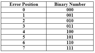
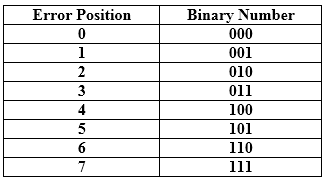
Hamming Code Parity bits: The bit which is appended to the original data of binary bits so that the total number of 1s is even or odd. Even parity: To check for even parity, if the total number of 1s is even, then the value of the parity bit is 0. If the total number of 1s occurrences is odd, then the value of the parity bit is 1. Odd Parity: To check for odd parity, if the total number of 1s is even, then the value of parity bit is 1. If the total number of 1s is odd, then the value of parity bit is 0. Algorithm of Hamming code: An information of 'd' bits are added to the redundant bits 'r' to form d+r. The location of each of the (d+r) digits is assigned a decimal value. The 'r' bits are placed in the positions 1,2,.....2k-1. At the receiving end, the parity bits are recalculated. The decimal value of the parity bits determines the position of an error. Relationship b/w Error position & binary number.
Let's understand the concept of Hamming code through an example: Suppose the original data is 1010 which is to be sent. Total number of data bits 'd' = 4 Number of redundant bits r : 2r >= d+r+1 2r>= 4+r+1 Therefore, the value of r is 3 that satisfies the above relation. Total number of bits = d+r = 4+3 = 7; Determining the position of the redundant bits The number of redundant bits is 3. The three bits are represented by r1, r2, r4. The position of the redundant bits is calculated with corresponds to the raised power of 2. Therefore, their corresponding positions are 1, 21, 22. The position of r1 = 1 The position of r2 = 2 The position of r4 = 4 Representation of Data on the addition of parity bits:
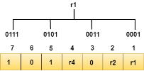
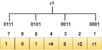
Determining the Parity bits Determining the r1 bit The r1 bit is calculated by performing a parity check on the bit positions whose binary representation includes 1 in the first position.
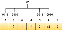
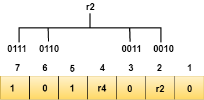
We observe from the above figure that the bit positions that includes 1 in the first position are 1, 3, 5, 7. Now, we perform the even-parity check at these bit positions. The total number of 1 at these bit positions corresponding to r1 is even, therefore, the value of the r1 bit is 0. Determining r2 bit The r2 bit is calculated by performing a parity check on the bit positions whose binary representation includes 1 in the second position.
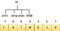
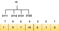
We observe from the above figure that the bit positions that includes 1 in the second position are 2, 3, 6, 7. Now, we perform the even-parity check at these bit positions. The total number of 1 at these bit positions corresponding to r2 is odd, therefore, the value of the r2 bit is 1. Determining r4 bit The r4 bit is calculated by performing a parity check on the bit positions whose binary representation includes 1 in the third position.
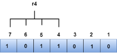
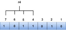
We observe from the above figure that the bit positions that includes 1 in the third position are 4, 5, 6, 7. Now, we perform the even-parity check at these bit positions. The total number of 1 at these bit positions corresponding to r4 is even, therefore, the value of the r4 bit is 0. Data transferred is given below:
Suppose the 4th bit is changed from 0 to 1 at the receiving end, then parity bits are recalculated. R1 bit The bit positions of the r1 bit are 1,3,5,7
We observe from the above figure that the binary representation of r1 is 1100. Now, we perform the even-parity check, the total number of 1s appearing in the r1 bit is an even number. Therefore, the value of r1 is 0. R2 bit The bit positions of r2 bit are 2,3,6,7.
We observe from the above figure that the binary representation of r2 is 1001. Now, we perform the even-parity check, the total number of 1s appearing in the r2 bit is an even number. Therefore, the value of r2 is 0. R4 bit The bit positions of r4 bit are 4,5,6,7.
We observe from the above figure that the binary representation of r4 is 1011. Now, we perform the even-parity check, the total number of 1s appearing in the r4 bit is an odd number. Therefore, the value of r4 is 1. The binary representation of redundant bits, i.e., r4r2r1 is 100, and its corresponding decimal value is 4. Therefore, the error occurs in a 4th bit position. The bit value must be changed from 1 to 0 to correct the error. |
Types of Errors
Errors can be classified into two categories: Single-Bit Error Burst Error Single-Bit Error: The only one bit of a given data unit is changed from 1 to 0 or from 0 to 1.
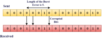
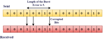
In the above figure, the message which is sent is corrupted as single-bit, i.e., 0 bit is changed to 1. Single-Bit Error does not appear more likely in Serial Data Transmission. For example, Sender sends the data at 10 Mbps, this means that the bit lasts only for 1 ?s and for a single-bit error to occurred, a noise must be more than 1 ?s. Single-Bit Error mainly occurs in Parallel Data Transmission. For example, if eight wires are used to send the eight bits of a byte, if one of the wire is noisy, then single-bit is corrupted per byte. Burst Error: The two or more bits are changed from 0 to 1 or from 1 to 0 is known as Burst Error. The Burst Error is determined from the first corrupted bit to the last corrupted bit.
The duration of noise in Burst Error is more than the duration of noise in Single-Bit. Burst Errors are most likely to occurr in Serial Data Transmission. The number of affected bits depends on the duration of the noise and data rate. |
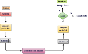
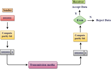
Single Parity Check Single Parity checking is the simple mechanism and inexpensive to detect the errors. In this technique, a redundant bit is also known as a parity bit which is appended at the end of the data unit so that the number of 1s becomes even. Therefore, the total number of transmitted bits would be 9 bits. If the number of 1s bits is odd, then parity bit 1 is appended and if the number of 1s bits is even, then parity bit 0 is appended at the end of the data unit. At the receiving end, the parity bit is calculated from the received data bits and compared with the received parity bit. This technique generates the total number of 1s even, so it is known as even-parity checking.
Drawbacks Of Single Parity Checking It can only detect single-bit errors which are very rare. If two bits are interchanged, then it cannot detect the errors.
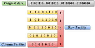
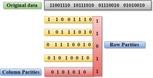
Two-Dimensional Parity Check Performance can be improved by using Two-Dimensional Parity Check which organizes the data in the form of a table. Parity check bits are computed for each row, which is equivalent to the single-parity check. In Two-Dimensional Parity check, a block of bits is divided into rows, and the redundant row of bits is added to the whole block. At the receiving end, the parity bits are compared with the parity bits computed from the received data.
Drawbacks Of 2D Parity Check If two bits in one data unit are corrupted and two bits exactly the same position in another data unit are also corrupted, then 2D Parity checker will not be able to detect the error. This technique cannot be used to detect the 4-bit errors or more in some cases. |
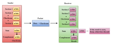
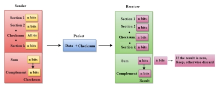
Checksum A Checksum is an error detection technique based on the concept of redundancy. It is divided into two parts: Checksum Generator A Checksum is generated at the sending side. Checksum generator subdivides the data into equal segments of n bits each, and all these segments are added together by using one's complement arithmetic. The sum is complemented and appended to the original data, known as checksum field. The extended data is transmitted across the network. Suppose L is the total sum of the data segments, then the checksum would be ?L
The Sender follows the given steps: The block unit is divided into k sections, and each of n bits. All the k sections are added together by using one's complement to get the sum. The sum is complemented and it becomes the checksum field. The original data and checksum field are sent across the network. Checksum Checker A Checksum is verified at the receiving side. The receiver subdivides the incoming data into equal segments of n bits each, and all these segments are added together, and then this sum is complemented. If the complement of the sum is zero, then the data is accepted otherwise data is rejected. The Receiver follows the given steps: The block unit is divided into k sections and each of n bits. All the k sections are added together by using one's complement algorithm to get the sum. The sum is complemented. If the result of the sum is zero, then the data is accepted otherwise the data is discarded. |
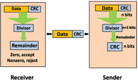
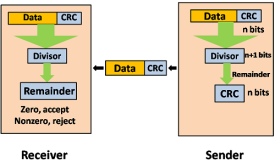
Cyclic Redundancy Check (CRC) CRC is a redundancy error technique used to determine the error. Following are the steps used in CRC for error detection: In CRC technique, a string of n 0s is appended to the data unit, and this n number is less than the number of bits in a predetermined number, known as division which is n+1 bits. Secondly, the newly extended data is divided by a divisor using a process is known as binary division. The remainder generated from this division is known as CRC remainder. Thirdly, the CRC remainder replaces the appended 0s at the end of the original data. This newly generated unit is sent to the receiver. The receiver receives the data followed by the CRC remainder. The receiver will treat this whole unit as a single unit, and it is divided by the same divisor that was used to find the CRC remainder. If the resultant of this division is zero which means that it has no error, and the data is accepted. If the resultant of this division is not zero which means that the data consists of an error. Therefore, the data is discarded.
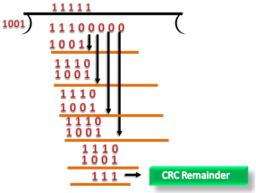
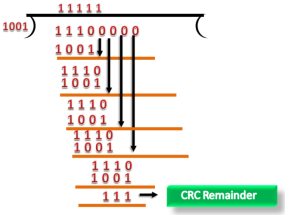
Let's understand this concept through an example: Suppose the original data is 11100 and divisor is 1001. CRC Generator A CRC generator uses a modulo-2 division. Firstly, three zeroes are appended at the end of the data as the length of the divisor is 4 and we know that the length of the string 0s to be appended is always one less than the length of the divisor. Now, the string becomes 11100000, and the resultant string is divided by the divisor 1001. The remainder generated from the binary division is known as CRC remainder. The generated value of the CRC remainder is 111. CRC remainder replaces the appended string of 0s at the end of the data unit, and the final string would be 11100111 which is sent across the network.
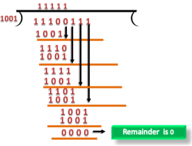
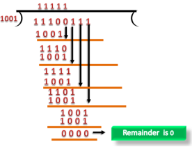
CRC Checker The functionality of the CRC checker is similar to the CRC generator. When the string 11100111 is received at the receiving end, then CRC checker performs the modulo-2 division. A string is divided by the same divisor, i.e., 1001. In this case, CRC checker generates the remainder of zero. Therefore, the data is accepted.
|
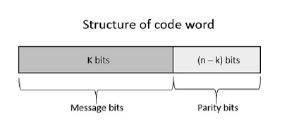
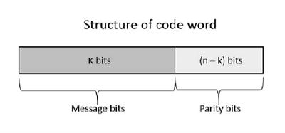
Error Control Coding Noise or Error is the main problem in the signal, which disturbs the reliability of the communication system. Error control coding is the coding procedure done to control the occurrences of errors. These techniques help in Error Detection and Error Correction. There are many different error correcting codes depending upon the mathematical principles applied to them. But, historically, these codes have been classified into Linear block codes and Convolution codes. Linear Block Codes In the linear block codes, the parity bits and message bits have a linear combination, which means that the resultant code word is the linear combination of any two code words. Let us consider some blocks of data, which contains k bits in each block. These bits are mapped with the blocks which has n bits in each block. Here n is greater than k. The transmitter adds redundant bits which are n−k bits. The ratio k/n is the code rate. It is denoted by r and the value of r is r < 1. The n−k bits added here, are parity bits. Parity bits help in error detection and error correction, and also in locating the data. In the data being transmitted, the left most bits of the code word correspond to the message bits, and the right most bits of the code word correspond to the parity bits. Systematic Code Any linear block code can be a systematic code, until it is altered. Hence, an unaltered block code is called as a systematic code. Following is the representation of the structure of code word, according to their allocation.
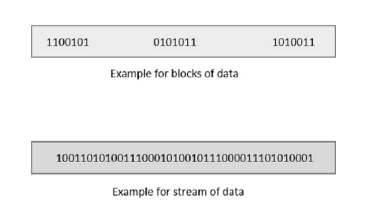
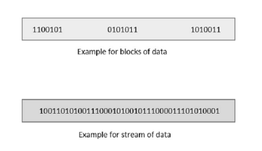
If the message is not altered, then it is called as systematic code. It means, the encryption of the data should not change the data. Convolution Codes So far, in the linear codes, we have discussed that systematic unaltered code is preferred. Here, the data of total n bits if transmitted, k bits are message bits and n−k bits are parity bits. In the process of encoding, the parity bits are subtracted from the whole data and the message bits are encoded. Now, the parity bits are again added and the whole data is again encoded. The following figure quotes an example for blocks of data and stream of data, used for transmission of information.
The whole process, stated above is tedious which has drawbacks. The allotment of buffer is a main problem here, when the system is busy. This drawback is cleared in convolution codes. Where the whole stream of data is assigned symbols and then transmitted. As the data is a stream of bits, there is no need of buffer for storage. Hamming Codes The linearity property of the code word is that the sum of two code words is also a code word. Hamming codes are the type of linear error correcting codes, which can detect up to two bit errors or they can correct one bit errors without the detection of uncorrected errors. While using the hamming codes, extra parity bits are used to identify a single bit error. To get from one-bit pattern to the other, few bits are to be changed in the data. Such number of bits can be termed as Hamming distance. If the parity has a distance of 2, one-bit flip can be detected. But this can't be corrected. Also, any two bit flips cannot be detected. However, Hamming code is a better procedure than the previously discussed ones in error detection and correction. BCH Codes BCH codes are named after the inventors Bose, Chaudari and Hocquenghem. During the BCH code design, there is control on the number of symbols to be corrected and hence multiple bit correction is possible. BCH codes is a powerful technique in error correcting codes. For any positive integers m ≥ 3 and t < 2m-1 there exists a BCH binary code. Following are the parameters of such code. Block length n = 2m-1 Number of parity-check digits n - k ≤ mt Minimum distance dmin ≥ 2t + 1 This code can be called as t-error-correcting BCH code. Cyclic Codes The cyclic property of code words is that any cyclic-shift of a code word is also a code word. Cyclic codes follow this cyclic property. For a linear code C, if every code word i.e., C = C1,C2,......Cn from C has a cyclic right shift of components, it becomes a code word. This shift of right is equal to n-1 cyclic left shifts. Hence, it is invariant under any shift. So, the linear code C, as it is invariant under any shift, can be called as a Cyclic code. Cyclic codes are used for error correction. They are mainly used to correct double errors and burst errors. Hence, these are a few error correcting codes, which are to be detected at the receiver. These codes prevent the errors from getting introduced and disturb the communication. They also prevent the signal from getting tapped by unwanted receivers. |
Stop and Wait Protocol Before understanding the stop and Wait protocol, we first know about the error control mechanism. The error control mechanism is used so that the received data should be exactly same whatever sender has sent the data. The error control mechanism is divided into two categories, i.e., Stop and Wait ARQ and sliding window. The sliding window is further divided into two categories, i.e., Go Back N, and Selective Repeat. Based on the usage, the people select the error control mechanism whether it is stop and wait or sliding window. What is Stop and Wait protocol? Here stop and wait means, whatever the data that sender wants to send, he sends the data to the receiver. After sending the data, he stops and waits until he receives the acknowledgment from the receiver. The stop and wait protocol is a flow control protocol where flow control is one of the services of the data link layer. It is a data-link layer protocol which is used for transmitting the data over the noiseless channels. It provides unidirectional data transmission which means that either sending or receiving of data will take place at a time. It provides flow-control mechanism but does not provide any error control mechanism. The idea behind the usage of this frame is that when the sender sends the frame then he waits for the acknowledgment before sending the next frame. Primitives of Stop and Wait Protocol The primitives of stop and wait protocol are: Sender side Rule 1: Sender sends one data packet at a time. Rule 2: Sender sends the next packet only when it receives the acknowledgment of the previous packet. Therefore, the idea of stop and wait protocol in the sender's side is very simple, i.e., send one packet at a time, and do not send another packet before receiving the acknowledgment. Receiver side Rule 1: Receive and then consume the data packet. Rule 2: When the data packet is consumed, receiver sends the acknowledgment to the sender. Therefore, the idea of stop and wait protocol in the receiver's side is also very simple, i.e., consume the packet, and once the packet is consumed, the acknowledgment is sent. This is known as a flow control mechanism. |
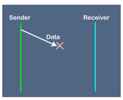
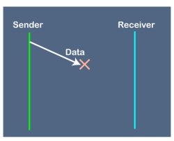
Disadvantages of Stop and Wait protocol The following are the problems associated with a stop and wait protocol: 1. Problems occur due to lost data
Suppose the sender sends the data and the data is lost. The receiver is waiting for the data for a long time. Since the data is not received by the receiver, so it does not send any acknowledgment. Since the sender does not receive any acknowledgment so it will not send the next packet. This problem occurs due to the lost data. In this case, two problems occur: Sender waits for an infinite amount of time for an acknowledgment. Receiver waits for an infinite amount of time for a data.
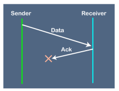
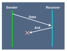
2. Problems occur due to lost acknowledgment
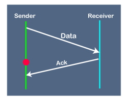
Suppose the sender sends the data and it has also been received by the receiver. On receiving the packet, the receiver sends the acknowledgment. In this case, the acknowledgment is lost in a network, so there is no chance for the sender to receive the acknowledgment. There is also no chance for the sender to send the next packet as in stop and wait protocol, the next packet cannot be sent until the acknowledgment of the previous packet is received. In this case, one problem occurs: Sender waits for an infinite amount of time for an acknowledgment. 3. Problem due to the delayed data or acknowledgment
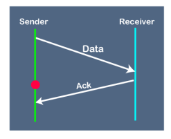
Suppose the sender sends the data and it has also been received by the receiver. The receiver then sends the acknowledgment but the acknowledgment is received after the timeout period on the sender's side. As the acknowledgment is received late, so acknowledgment can be wrongly considered as the acknowledgment of some other data packet. |
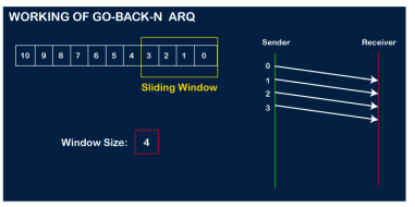
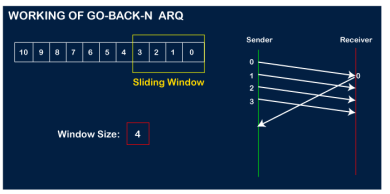
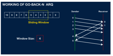
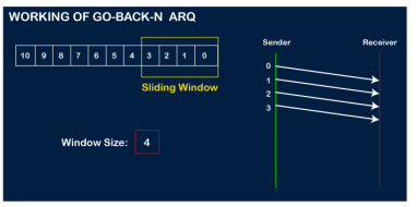
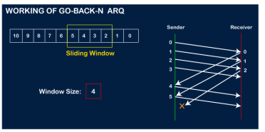
In Go-Back-N ARQ, N is the sender's window size. Suppose we say that Go-Back-3, which means that the three frames can be sent at a time before expecting the acknowledgment from the receiver. It uses the principle of protocol pipelining in which the multiple frames can be sent before receiving the acknowledgment of the first frame. If we have five frames and the concept is Go-Back-3, which means that the three frames can be sent, i.e., frame no 1, frame no 2, frame no 3 can be sent before expecting the acknowledgment of frame no 1. In Go-Back-N ARQ, the frames are numbered sequentially as Go-Back-N ARQ sends the multiple frames at a time that requires the numbering approach to distinguish the frame from another frame, and these numbers are known as the sequential numbers. The number of frames that can be sent at a time totally depends on the size of the sender's window. So, we can say that 'N' is the number of frames that can be sent at a time before receiving the acknowledgment from the receiver. If the acknowledgment of a frame is not received within an agreed-upon time period, then all the frames available in the current window will be retransmitted. Suppose we have sent the frame no 5, but we didn't receive the acknowledgment of frame no 5, and the current window is holding three frames, then these three frames will be retransmitted. The sequence number of the outbound frames depends upon the size of the sender's window. Suppose the sender's window size is 2, and we have ten frames to send, then the sequence numbers will not be 1,2,3,4,5,6,7,8,9,10. Let's understand through an example. N is the sender's window size. If the size of the sender's window is 4 then the sequence number will be 0,1,2,3,0,1,2,3,0,1,2, and so on. The number of bits in the sequence number is 2 to generate the binary sequence 00,01,10,11. Working of Go-Back-N ARQ Suppose there are a sender and a receiver, and let's assume that there are 11 frames to be sent. These frames are represented as 0,1,2,3,4,5,6,7,8,9,10, and these are the sequence numbers of the frames. Mainly, the sequence number is decided by the sender's window size. But, for the better understanding, we took the running sequence numbers, i.e., 0,1,2,3,4,5,6,7,8,9,10. Let's consider the window size as 4, which means that the four frames can be sent at a time before expecting the acknowledgment of the first frame. Step 1: Firstly, the sender will send the first four frames to the receiver, i.e., 0,1,2,3, and now the sender is expected to receive the acknowledgment of the 0th frame.
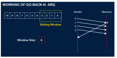
Let's assume that the receiver has sent the acknowledgment for the 0 frame, and the receiver has successfully received it.
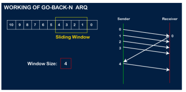
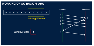
The sender will then send the next frame, i.e., 4, and the window slides containing four frames (1,2,3,4).
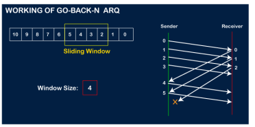
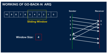
The receiver will then send the acknowledgment for the frame no 1. After receiving the acknowledgment, the sender will send the next frame, i.e., frame no 5, and the window will slide having four frames (2,3,4,5).
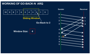
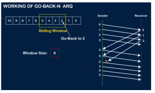
Now, let's assume that the receiver is not acknowledging the frame no 2, either the frame is lost, or the acknowledgment is lost. Instead of sending the frame no 6, the sender Go-Back to 2, which is the first frame of the current window, retransmits all the frames in the current window, i.e., 2,3,4,5.
|
