Switching Modes The layer 2 switches are used for transmitting the data on the data link layer, and it also performs error checking on transmitted and received frames. The layer 2 switches forward the packets with the help of MAC address. Different modes are used for forwarding the packets known as Switching modes. In switching mode, Different parts of a frame are recognized. The frame consists of several parts such as preamble, destination MAC address, source MAC address, user's data, FCS.
There are three types of switching modes: Store-and-forward Cut-through Fragment-free
Store-and-forward
Store-and-forward is a technique in which the intermediate nodes store the received frame and then check for errors before forwarding the packets to the next node. The layer 2 switch waits until the entire frame has received. On receiving the entire frame, switch store the frame into the switch buffer memory. This process is known as storing the frame. When the frame is stored, then the frame is checked for the errors. If any error found, the message is discarded otherwise the message is forwarded to the next node. This process is known as forwarding the frame. CRC (Cyclic Redundancy Check) technique is implemented that uses a number of bits to check for the errors on the received frame. The store-and-forward technique ensures a high level of security as the destination network will not be affected by the corrupted frames. Store-and-forward switches are highly reliable as it does not forward the collided frames. Cut-through Switching
Cut-through switching is a technique in which the switch forwards the packets after the destination address has been identified without waiting for the entire frame to be received. Once the frame is received, it checks the first six bytes of the frame following the preamble, the switch checks the destination in the switching table to determine the outgoing interface port, and forwards the frame to the destination. It has low latency rate as the switch does not wait for the entire frame to be received before sending the packets to the destination. It has no error checking technique. Therefore, the errors can be sent with or without errors to the receiver. A Cut-through switching technique has low wait time as it forwards the packets as soon as it identifies the destination MAC address. In this technique, collision is not detected, if frames have collided will also be forwarded. Fragment-free Switching
A Fragment-free switching is an advanced technique of the Cut-through Switching. A Fragment-free switching is a technique that reads atleast 64 bytes of a frame before forwarding to the next node to provide the error-free transmission. It combines the speed of Cut-through Switching with the error checking functionality. This technique checks the 64 bytes of the ethernet frame where addressing information is available. A collision is detected within 64 bytes of the frame, the frames which are collided will not be forwarded further.
|
Store-and-forward Switching | Cut-through Switching |
Store-and-forward Switching is a technique that waits until the entire frame is received. | Cut-through Switching is a technique that checks the first 6 bytes following the preamble to identify the destination address. |
It performs error checking functionality. If any error is found in the frame, the frame will be discarded otherwise forwarded to the next node. | It does not perform any error checking. The frame with or without errors will be forwarded. |
It has high latency rate as it waits for the entire frame to be received before forwarding to the next node. | It has low latency rate as it checks only six bytes of the frame to determine the destination address. |
It is highly reliable as it forwards only error-free packets. | It is less reliable as compared to Store-and-forward technique as it forwards error prone packets as well. |
It has a high wait time as it waits for the entire frame to be received before taking any forwarding decisions. | It has low wait time as cut-through switches do not store the whole frame or packets. |
|
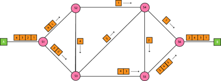
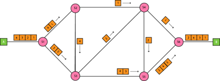
Packet Switching The packet switching is a switching technique in which the message is sent in one go, but it is divided into smaller pieces, and they are sent individually. The message splits into smaller pieces known as packets and packets are given a unique number to identify their order at the receiving end. Every packet contains some information in its headers such as source address, destination address and sequence number. Packets will travel across the network, taking the shortest path as possible. All the packets are reassembled at the receiving end in correct order. If any packet is missing or corrupted, then the message will be sent to resend the message. If the correct order of the packets is reached, then the acknowledgment message will be sent.
Approaches Of Packet Switching: There are two approaches to Packet Switching: Datagram Packet switching: It is a packet switching technology in which packet is known as a datagram, is considered as an independent entity. Each packet contains the information about the destination and switch uses this information to forward the packet to the correct destination. The packets are reassembled at the receiving end in correct order. In Datagram Packet Switching technique, the path is not fixed. Intermediate nodes take the routing decisions to forward the packets. Datagram Packet Switching is also known as connectionless switching.
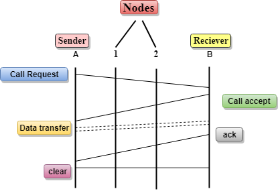
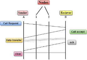
Virtual Circuit Switching Virtual Circuit Switching is also known as connection-oriented switching. In the case of Virtual circuit switching, a preplanned route is established before the messages are sent. Call request and call accept packets are used to establish the connection between sender and receiver. In this case, the path is fixed for the duration of a logical connection. Let's understand the concept of virtual circuit switching through a diagram:
In the above diagram, A and B are the sender and receiver respectively. 1 and 2 are the nodes. Call request and call accept packets are used to establish a connection between the sender and receiver. When a route is established, data will be transferred. After transmission of data, an acknowledgment signal is sent by the receiver that the message has been received. If the user wants to terminate the connection, a clear signal is sent for the termination. Differences b/w Datagram approach and Virtual Circuit approach
Advantages Of Packet Switching: Cost-effective: In packet switching technique, switching devices do not require massive secondary storage to store the packets, so cost is minimized to some extent. Therefore, we can say that the packet switching technique is a cost-effective technique. Reliable: If any node is busy, then the packets can be rerouted. This ensures that the Packet Switching technique provides reliable communication. Efficient: Packet Switching is an efficient technique. It does not require any established path prior to the transmission, and many users can use the same communication channel simultaneously, hence makes use of available bandwidth very efficiently. Disadvantages Of Packet Switching: Packet Switching technique cannot be implemented in those applications that require low delay and high-quality services. The protocols used in a packet switching technique are very complex and requires high implementation cost. If the network is overloaded or corrupted, then it requires retransmission of lost packets. It can also lead to the loss of critical information if errors are nor recovered. |
Representation of 8 Bit Octet
The above representation shows the structure of 8- bit octet. Now, we will see how to obtain the binary representation of the above IP address, i.e., 66.94.29.13
Step 1: First, we find the binary number of 66.
To obtain 66, we put 1 under 64 and 2 as the sum of 64 and 2 is equal to 66 (64+2=66), and the remaining bits will be zero, as shown above. Therefore, the binary bit version of 66 is 01000010. Step 2: Now, we calculate the binary number of 94.
To obtain 94, we put 1 under 64, 16, 8, 4, and 2 as the sum of these numbers is equal to 94, and the remaining bits will be zero. Therefore, the binary bit version of 94 is 01011110. Step 3: The next number is 29.
To obtain 29, we put 1 under 16, 8, 4, and 1 as the sum of these numbers is equal to 29, and the remaining bits will be zero. Therefore, the binary bit version of 29 is 00011101. Step 4: The last number is 13.
To obtain 13, we put 1 under 8, 4, and 1 as the sum of these numbers is equal to 13, and the remaining bits will be zero. Therefore, the binary bit version of 13 is 00001101.
|
Address format The address format of IPv4:
The address format of IPv6:
|
| Ipv4 | Ipv6 |
Address length | IPv4 is a 32-bit address. | IPv6 is a 128-bit address. |
Fields | IPv4 is a numeric address that consists of 4 fields which are separated by dot (.). | IPv6 is an alphanumeric address that consists of 8 fields, which are separated by colon. |
Classes | IPv4 has 5 different classes of IP address that includes Class A, Class B, Class C, Class D, and Class E. | IPv6 does not contain classes of IP addresses. |
Number of IP address | IPv4 has a limited number of IP addresses. | IPv6 has a large number of IP addresses. |
VLSM | It supports VLSM (Virtual Length Subnet Mask). Here, VLSM means that Ipv4 converts IP addresses into a subnet of different sizes. | It does not support VLSM. |
Address configuration | It supports manual and DHCP configuration. | It supports manual, DHCP, auto-configuration, and renumbering. |
Address space | It generates 4 billion unique addresses | It generates 340 undecillion unique addresses. |
End-to-end connection integrity | In IPv4, end-to-end connection integrity is unachievable. | In the case of IPv6, end-to-end connection integrity is achievable. |
Security features | In IPv4, security depends on the application. This IP address is not developed in keeping the security feature in mind. | In IPv6, IPSEC is developed for security purposes. |
Address representation | In IPv4, the IP address is represented in decimal. | In IPv6, the representation of the IP address in hexadecimal. |
Fragmentation | Fragmentation is done by the senders and the forwarding routers. | Fragmentation is done by the senders only. |
Packet flow identification | It does not provide any mechanism for packet flow identification. | It uses flow label field in the header for the packet flow identification. |
Checksum field | The checksum field is available in IPv4. | The checksum field is not available in IPv6. |
Transmission scheme | IPv4 is broadcasting. | On the other hand, IPv6 is multicasting, which provides efficient network operations. |
Encryption and Authentication | It does not provide encryption and authentication. | It provides encryption and authentication. |
Number of octets | It consists of 4 octets. | It consists of 8 fields, and each field contains 2 octets. Therefore, the total number of octets in IPv6 is 16. |
|


