Unit-4
Single phase induction motors
Q1. Explain constructional features of induction motor in detail?
Ans :
A. Stator of Single Phase Induction Motor :
1. The stator of the single-phase induction motor has laminated stamping to reduce eddy current losses on its periphery.
2. The slots are provided on its stamping to carry stator or main winding. Stampings are made up of silicon steel to reduce the hysteresis losses.
3. When we apply a single phase AC supply to the stator winding, the magnetic field gets produced, and the motor rotates at speed slightly less than the synchronous speed
4. The construction of the stator of the single-phase induction motor is similar to that of three phase induction motor except there are two dissimilarities in the winding part of the single phase induction motor.
5. Firstly, the single-phase induction motors are mostly provided with concentric coils. We can easily adjust the number of turns per coil can with the help of concentric coils. The mmf distribution is almost sinusoidal.
6. Except for shaded pole motor, the asynchronous motor has two stator windings namely the main winding and the auxiliary winding. These two windings are placed in space quadrature to each other.
B. Rotor of Single Phase Induction Motor:
1. The construction of the rotor of the single-phase induction motor is similar to the squirrel cage three-phase induction motor.
2. The rotor is cylindrical and has slots all over its periphery.
3.The slots are not made parallel to each other but are a little bit skewed as the skewing prevents magnetic locking of stator and rotor teeth and makes the working of induction motor more smooth and quieter (i.e. less noisy).
4. The squirrel cage rotor consists of aluminium, brass or copper bars. These aluminium or copper bars are called rotor conductors and placed in the slots on the periphery of the rotor. The copper or aluminium rings permanently short the rotor conductors called the end rings.
5. To provide mechanical strength, these rotor conductors are braced to the end ring and hence form a complete closed circuit resembling a cage and hence got its name as squirrel cage induction motor.
6. As end rings permanently short the bars, the rotor electrical resistance is very small and it is not possible to add external resistance as the bars get permanently shorted. The absence of slip ring and brushes make the construction of single phase induction motor very simple and robust.
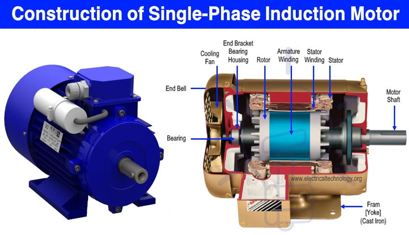
Fig : single phase induction motor
Q2.Explain Double revolving field theory in detail?
Ans :
1. The double revolving field theory of a single phase induction motor states that a pulsating magnetic field is resolved into two rotating magnetic fields.
2. They are equal in magnitude but opposite in directions. The induction motor responds to each of the magnetic fields separately.
3. The net torque in the motor is equal to the sum of the torque due to each of the two magnetic fields.
The equation for an alternating magnetic field is given as:

4. Where βmax is the maximum value of the sinusoidally distributed air gap flux density produced by a properly distributed stator winding carrying an alternating current of the frequency ω, and α is the space displacement angle measured from the axis of the stator winding.
As we know,
 )
)
So, the equation (1) can be written as

5. The first term of the right-hand side of the equation (2) represents the revolving field moving in the positive α direction. It is known as a Forward Rotating field. Similarly, the second term shows the revolving field moving in the negative α direction and is known as the Backward Rotating field.
6. The direction in which the single phase motor is started initially is known as the positive direction. Both the revolving field rotates at the synchronous speed. ωs = 2πf in the opposite direction. Thus, the pulsating magnetic field is resolved into two rotating magnetic fields. Both are equal in magnitude and opposite in direction but at the same frequency.
7. At the standstill condition, the induced voltages are equal and opposite as a result; the two torques are also equal and opposite. Thus, the net torque is zero and, therefore, a single phase induction motor has no starting torque.
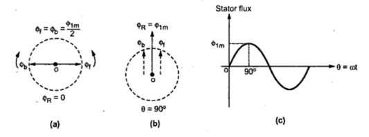
Fig :Double revolving field theory
Q3. Explain Exact Equivalent Circuit with circuit diagram?
Ans :
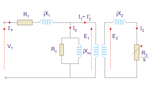
Fig : Equivalent Circuit
Here, R1 is the winding resistance of the stator.
X1 is the inductance of the stator winding.
Rc is the core loss component.
XM is the magnetizing reactance of the winding.
R2/s is the power of the rotor, which includes output mechanical power and copper loss of rotor.
If we draw the circuit with referred to the stator then the circuit will look like-
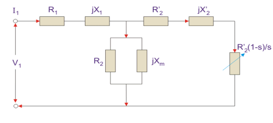
Fig : Equivalent circuit
Here all the other parameters are same except-
R2’ is the rotor winding resistance with referred to stator winding.
X2’ is the rotor winding inductance with referred to stator winding.
R2 (1 – s) / s is the resistance which shows the power which is converted to mechanical power output or useful power. The power dissipated in that resistor is the useful power output or shaft power.
4. The approximate equivalent circuit is drawn just to simplify our calculation by deleting one node. The shunt branch is shifted towards the primary side.
5. This has been done as the voltage drop between the stator resistance and inductance is less and there is not much difference between the supply voltage and the induced voltage.
Q4. Explain Split Phase Induction Motor in detail with phasor diagram?
Ans:
1. The Split Phase Motor is also known as a Resistance Start Motor. It has a single cage rotor, and its stator has two windings known as main winding and starting winding.
2. Both the windings are displaced 90 degrees in space. The main winding has very low resistance and a high inductive reactance whereas the starting winding has high resistance and low inductive reactance.
3. Split-Phase-Indcution-Motor-resistor is connected in series with the auxiliary winding. The current in the two windings is not equal as a result the rotating field is not uniform.
4. Hence, the starting torque is small, of the order of 1.5 to 2 times of the started running torque. At the starting of the motor both the windings are connected in parallel.
5. As soon as the motor reaches the speed of about 70 to 80 % of the synchronous speed the starting winding is disconnected automatically from the supply mains.
6. If the motors are rated about 100 Watt or more, a centrifugal switch is used to disconnect the starting winding and for the smaller rating motors relay is used for the disconnecting of the winding.
7. A relay is connected in series with the main winding. At the starting, the heavy current flows in the circuit, and the contact of the relay gets closed.
8. Thus, the starting winding is in the circuit, and as the motor attains the predetermined speed, the current in the relay starts decreasing. Therefore, the relay opens and disconnects the auxiliary winding from the supply, making the motor runs on the main winding only.
--The phasor diagram of the Split Phase Induction Motor is shown below.
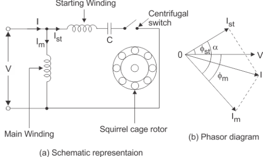
Fig: Schematic diagram and phasor diagram of split phase induction motor
9. Split-Phase-Indcution-Motor-The current in the main winding (IM) lag behind the supply voltage V almost by the 90-degree angle. The current in the auxiliary winding IA is approximately in phase with the line voltage.
10. Thus, there exists the time difference between the currents of the two windings. The time phase difference ϕ is not 90 degrees, but of the order of 30 degrees. This phase difference is enough to produce a rotating magnetic field.
Q5. State Applications of Split Phase Induction Motor?
Ans :
This type of motors are cheap and are suitable for easily starting loads where the frequency of starting is limited. This type of motor is not used for drives which require more than 1 KW because of the low starting torque. The various applications are as follows:-
1. Used in the washing machine, and air conditioning fans.
2. The motors are used in mixer grinder, floor polishers.
3. Blowers, Centrifugal pumps
4. Drilling and lathe machine.
Q6. Explain Methods of starting using auxiliary winding?
Ans :
A. Permanent split capacitor method [psc]
1. In a capacitor start method, a capacitor has to be disconnected after the motor reaches to a specific speed of motor.
2. But in this method, a run-type capacitor is placed in series with the start winding or auxiliary winding. This capacitor is used continuously, and it doesn’t require any switch to disconnect it as it is not used to start the motor only.
3.The starting torque of the PSC is similar to the spilt-phase motors, but with low starting current.
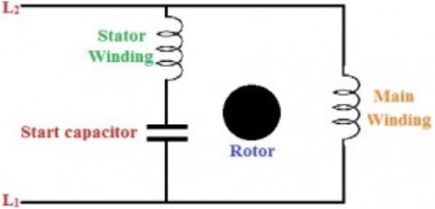
Fig : Permanent split capacitor method [psc]
B. Capacitor start and capacitor run
1. The features of the capacitor start and PSC methods can be combined with this method.
2. Run capacitor is connected in series with the start winding or auxiliary winding, and a start capacitor is connected in the circuit using a normally closed switch while starting the motor.
3. Start capacitor provides starting boost to motor and PSC provides high running to the motor. It is more costly, but still facilitates high starting and breakdown torque along with smooth running characteristics at high horsepower ratings.
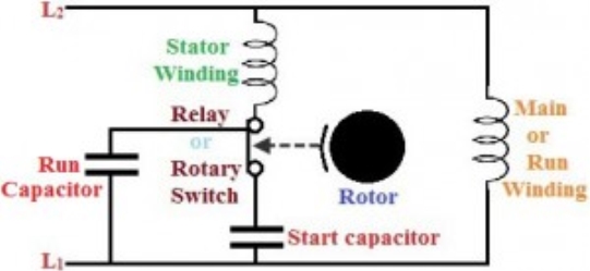
Fig :Capacitor Start Capacitor Run
Q7. Explain the Development of equivalent circuit ?
Ans :
Input power to stator- 3 V1I1Cos(Ɵ).
Where, V1 is the stator voltage applied.
I1 is the current drawn by the stator winding.
Cos(Ɵ) is the stator power stator.
Rotor input =
Power input- Stator copper and iron losses.
Rotor Copper loss = Slip × power input to the rotor.
Developed Power = (1 – s) × Rotor input power.
Equivalent Circuit of a Single Phase Induction Motor
1. There is a difference between single phase and three phase equivalent circuits. The single phase induction motor circuit is given by double revolving field theory which states that-a stationary pulsating magnetic field might be resolved into two rotating fields, both having equal magnitude but opposite in direction.
2. So the net torque induced is zero at standstill. Here, the forward rotation is called the rotation with slip s and the backward rotation is given with a slip of (2 – s). The equivalent circuit is-
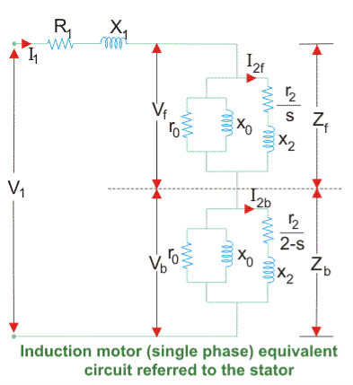
Fig : Development of equivalent circuit
3. Equivalent circuit of a single phase induction motor
In most of the cases the core loss component r0 is neglected as this value is quite large and does not affect much in the calculation.
Here, Zf shows the forward impedance and Zb shows the backward impedance.
Also, the sum of forward and backward slip is 2 so in case of backward slip, it is replaced by (2 – s).
R1 = Resistance of stator winding.
X1 = Inductive reactance of the stator winding.
Xm = Magnetising reactance.
R2’ = Rotor Reactance with referred to stator.
X2’ = Rotor inductive reactance with referred to stator.
Q8. Explain blocked rotor test in brief ?
Ans :
1. The induction motors are widely used in the industries and consume maximum power. To improve its performance characteristics certain tests have been designed like no-load test and block rotor test, etc.
2. A blocked rotor test is normally performed on an induction motor to find out the leakage impedance.
3. Apart from it, other parameters such as torque, motor, short-circuit current at normal voltage, and many more could be found from this test. Blocked rotor test is analogous to the short circuit test of transformer.
4. Here shaft of the motor is clamped i.e. blocked so it cannot move and rotor winding is short circuited.
5.In slip ring motor rotor winding is short circuited through slip rings and in cage motors, rotors bars are permanently short circuited.
6. The testing of the induction motor is a little bit complex as the resultant value of leakage impedance may get affected by rotor position, rotor frequency and by magnetic dispersion of the leakage flux path.
7.These effects could be minimized by conducting a block rotor current test on squirrel-cage rotors.
Q9. Derive resistance and reactance values calculated in block rotor test?
Ans :
Resistance and Leakage Reactance Values
In blocked rotor test, core loss is very low due to the supply of low voltage and frictional loss is also negligible as rotor is stationary, but stator cupper losses and the rotor cupper losses are reasonably high.
Let us take denote copper loss by Wcu.
Therefore,

Where, Wc = core loss

Where, R01 = Motor winding of stator and rotor as per phase referred to stator.
Thus,

Now let us consider
Is = short circuit current
Vs = short circuit voltage
Z0 = short circuit impedance as referred to stator
Therefore,

X01 = Motor leakage reactance per phase referred to stator can be calculated as
Stator reactance X1 and rotor reactance per phase referred to stator X2 are normally assumed equal.
Therefore,


Similarly, stator resistance per phase R1 and rotor resistance per phase referred to stator R2 can be calculated as follows:
First some suitable test are done on stator windings to find the value of R1 and then to find R2 subtract the R1 from R01

Q10. Explain No load test in brief?
Ans:
1. The impedance of magnetizing path of induction motor is large enough to obstruct flow of current. Therefore, small current is applied to the machine due to which there is a fall in the stator-impedance value and rated voltage is applied across the magnetizing branch.
2. But the drop in stator-impedance value and power dissipated due to stator resistance are very small in comparison to applied voltage. Therefore, there values are neglected and it is assumed that total power drawn is converted into core loss.
3. The air gap in magnetizing branch in an induction motor slowly increases the exciting current and the no load stator I2R loss can be recognized.
4. One should keep in mind that current should not exceed its rated value otherwise rotor accelerates beyond its limit.
5. The test is performed at poly-phase voltages and rated frequency applied to the stator terminals. When motor runs for some times and bearings get lubricated fully, at that time readings of applied voltage, input current and input power are taken.
Q11. Derive equation for Calculation of Power of Equivalent Circuit ?
Ans:
Find Zf and Zb.
Find stator current which is given by Stator voltage/Total circuit impedance.
Then find the input power which is given by
Stator voltage × Stator current × Cos(Ɵ)
Where, Ɵ is the angle between the stator current and voltage.
Power Developed (Pg) is the difference between forward field power and backward power. The forward and backward power is given by the power dissipated in the respective resistors.
The rotor copper loss is given by- slip × Pg.
Output Power is given by-
Pg – s × Pg – Rotational loss.
The rotational losses include friction loss, windage loss, Core loss.
Efficiency can also be calculated by diving output power by input power.
Q 12. State and explain Determination of parameters of single phase induction motor ?
Ans :
1. A stationary pulsating magnetic field might be resolved into two rotating fields, both having equal magnitude but opposite in direction.
2. So the net torque induced is zero at standstill. Here, the forward rotation is called the rotation with slip s and the backward rotation is given with a slip of (2 – s). The equivalent circuit is-
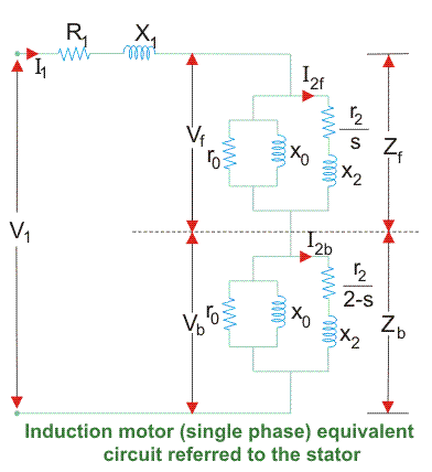
Fig . Equivalent circuit
3. In most of the cases the core loss component r0 is neglected as this value is quite large and does not affect much in the calculation.
4. Here, Zf shows the forward impedance and Zb shows the backward impedance.
Also, the sum of forward and backward slip is 2 so in case of backward slip, it is replaced by (2 – s).
R1 = Resistance of stator winding.
X1 = Inductive reactance of the stator winding.
Xm = Magnetising reactance.
R2’ = Rotor Reactance with referred to stator.
X2’ = Rotor inductive reactance with referred to stator.