Unit 5
Special machines
Q1. Explain construction and working of hysteresis motor?
Ans:
Hysteresis Motor Construction
A hysteresis motor is constructed of five main components:
1. Stator
2. Single phase stator winding
3. Rotor
4. Shaft
5. Shading coil
The two most important components of the hysteresis motor are the stator and rotor:
1. Stator: Stator of hysteresis motor is designed in a particular manner to produce synchronous revolving field from single phase supply. Stator carries two windings, (a) main winding (b) auxiliary winding. In another type of design of hysteresis motor the stator holds the poles of shaded type.
2. Rotor: Rotor of hysteresis motor is made of magnetic material that has high hysteresis loss property. Example of this type of materials is chrome, cobalt steel or alnico or alloy. Hysteresis loss becomes high due to large area of hysteresis loop.
3. Rotor does not carry any winding or teeth. The magnetic cylindrical portion of the rotor is assembled over shaft through arbor of nonmagnetic material like brass.
4. Rotor is provided with high resistance to reduce eddy current loss.
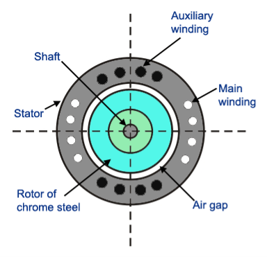
Fig : Hysteresis motor
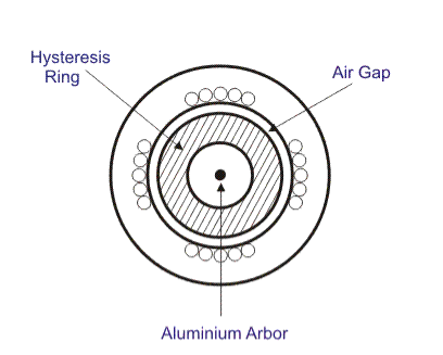
Fig : external part of hysteresis motor
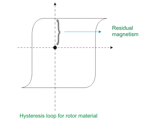
Fig : graph for hysteresis motor
Working Principle of Hysteresis Motor
Starting behaviour of a hysteresis motor is like a single phase induction motor and running behaviour is same as a synchronous motor. Step by step its behavior can be realized in the working principle that is given below.
A. At the Starting Condition
1. When stator is energized with single phase AC supply, rotating magnetic field is produced in stator.
2. To maintain the rotating magnetic field the main and auxiliary windings must be supplied continuously at start as well as in running conditions.
3. At the starting, by induction phenomenon, secondary voltage is induced in the rotor by stator rotating magnetic field. Hence eddy current is generated to flow in the rotor and it develops rotor.
4. Thus eddy current torque is developed along with the hysteresis torque in the rotor. Hysteresis torque in the rotor develops as the rotor magnetic material is with high hysteresis loss property and high retentively.
5. The rotor goes under the slip frequency before going to the steady state running condition.
6. So it can be said that when the rotor starts to rotate with the help of these eddy current torque due to induction phenomenon, it behalves like a single phase induction motor.
B. At Steady State Running Condition
1. When the speed of the rotor reaches near about the synchronous speed, the stator pulls the rotor into synchronism.
2. At the condition of synchronism, the relative motion between stator field and rotor field vanishes. So there is no further induction phenomenon to continue. Hence no eddy current to generate in the rotor. Thus the torque due to eddy-currents vanishes.
3. At the time of rotor’s rotation at the synchronous speed, rotating magnetic field flux in the stator produces poles on the rotor by induction; they are named as north (N) and south (S) poles. Thus rotor behaves as a permanent magnet having rotor axis as the induced magnetic axis.
4. For high residual magnetism or retentivity the rotor pole strength remains sustainable or unchanged. Again higher the retentivity, higher is the hysteresis torque and the hysteresis torque is independent of the rotor speed always. The high retentivity enables the continuous magnetic locking between stator and rotor and thus the motor rotates at synchronous speed.
5. The maximum work done to establish the hysteresis losses under the magnetization cycle in the rotor is equal to the surface area inside B-H hysteresis curve.
6. In lower load torque, the needed work done to rotate the rotor is equal to maximum magnetizing work of hysteresis phenomenon available already in the rotor. So induced magnetic pole axis always follows the rotating magnetic field axis of stator without any lag angle.
7. But when the load torque is sufficiently high, the maximum magnetizing work in rotor by hysteresis phenomenon cannot fulfill the work done needed to rotate the rotor.
8. So the induced magnetic field axis or rotor pole axis lags the rotating magnetic field axis of the stator at an angle δh. Hence the rotor pole axis tries to catch up the stator magnetic field axis.
9. If the load torque is increased, this lagging angle will be increased up to δmax before dropping below the synchronous condition.
10. The rotor poles are attracted towards the moving stator poles and runs at synchronous speed.
Q2. Explain construction and working of Switched reluctance motor ?
Ans:
Construction of Switched Reluctance Motor
Variable Reluctance Motor or Switched Reluctance Motor has two different constructions: Singly Salient Construction and Doubly Salient Construction. Stator and rotor magnetic circuits are laminated to reduce the core losses in both type of SRM.
A: Singly Salient Construction:
1. A singly salient construction SRM comprises of a non-salient stator and a salient two pole rotor.
2.The rotor do not have any winding wound over it but the stator have two phase winding as shown in figure below.
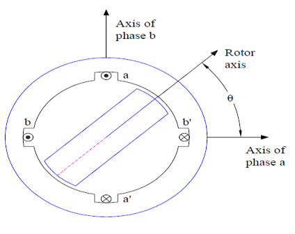
Fig : switched reluctance motor
3. It should be noted that, in actual SRM the number of phase winding on stator may be more than two. Since the rotor is of salient construction, the inductance of stator phase winding varies with the rotor position.
4. The inductance is minimum when the rotor axis and stator phase winding axis coincides whereas it is maximum when both the axis are in quadrature.
B: Doubly Salient Construction:
1. Unlike singly salient type, the stator of doubly salient Switched Reluctance Motor is of salient construction and consists of four poles as shown in figure below.
2.The rotor do not carry any winding and is of salient construction but have two poles. Thus this type of SRM is a hetropolar motor where the numbers of stator and rotor poles are not same.
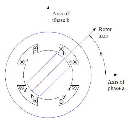
Fig : Double salient construction
3. The stator phase windings are concentrated winding. These concentrated windings on radially opposite poles are either connected in series or parallel to result into two phase winding on stator.
4. A doubly salient type Switched Reluctance Motor or variable Reluctance Motor produces more torque as compared to singly salient type for the same size. Therefore a doubly SRM is more common and widely used.
Working principle of Switched Reluctance Motor (SRM)
1. As we know that magnetic flux have a tendency to flow through lowest reluctance path, therefore rotor always tends to align along the minimum reluctance path. This is the basic working principle of Switched Reluctance Motor or Variable Reluctance Motor.
2. Thus rotor rotation in clockwise direction is achieved by energizing the phase winding in a ABC sequence. If rotor rotation in anti-clockwise direction is require, stator phase winding must be energized in ACB sequence.
3. It must also be noted that, a particular phase winding must be energized / de-energized in synchronism with rotor position. This means as soon as the rotor align along the A phase, B phase must be energized and A phase must be de-energized if clockwise rotor rotation is required.
To better understand the working principle, carefully observe the animation of Switched Reluctance Motor given below.
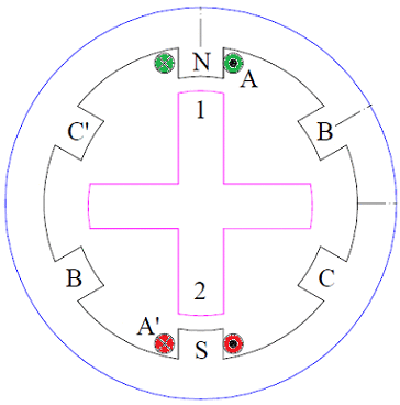
Fig : working diagram
Q3.explain Stepper motor working principle?
Ans:
1. The stepper motor rotor is a permanent magnet, when the current flows through the stator winding, the stator winding to produce a vector magnetic field.
2. The magnetic field drives the rotor to rotate by an angle so that the pair of magnetic fields of the rotor and the magnetic field direction of the stator are consistent.
3. When the stator's vector magnetic field is rotated by an angle, the rotor also rotates with the magnetic field at an angle. Each time an electrical pulse is input, the motor rotates one degree further.
4. The angular displacement it outputs is proportional to the number of pulses input and the speed is proportional to the pulse frequency. Change the order of winding power, the motor will reverse.
5. Therefore, it can control the rotation of the stepping motor by controlling the number of pulses, the frequency and the electrical sequence of each phase winding of the motor.
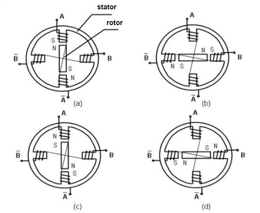
Fig :phases of operating stepper motor
Q4. State and explain Brushless DC motor constructional features?
Ans:
1. BLDC motors can be constructed in different physical configurations. Depending on the stator windings, these can be configured as single-phase, two-phase, or three-phase motors.
2. However, three-phase BLDC motors with permanent magnet rotor are most commonly used.
A. Stator
1. Stator of a BLDC motor made up of stacked steel laminations to carry the windings. These windings are placed in slots which are axially cut along the inner periphery of the stator.
2. These windings can be arranged in either star or delta. However, most BLDC motors have three phase star connected stator.
3. Each winding is constructed with numerous interconnected coils, where one or more coils are placed in each slot. In order to form an even number of poles, each of these windings is distributed over the stator periphery.
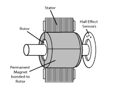
Fig : brushless DC motor
4. The stator must be chosen with the correct rating of the voltage depending on the power supply capability. For robotics, automotive and small actuating applications, 48 V or less voltage BLDC motors are preferred.
5. For industrial applications and automation systems, 100 V or higher rating motors are used.
B :Rotor
1.BLDC motor incorporates a permanent magnet in the rotor. The number of poles in the rotor can vary from 2 to 8 pole pairs with alternate south and north poles depending on the application requirement.
2. In order to achieve maximum torque in the motor, the flux density of the material should be high.
3. A proper magnetic material for the rotor is needed to produce required magnetic field density.
C: Hall Sensors
1. Hall sensor provides the information to synchronize stator armature excitation with rotor position. Since the commutation of BLDC motor is controlled electronically, the stator windings should be energized in sequence in order to rotate the motor.
2. Before energizing a particular stator winding, acknowledgment of rotor position is necessary. So the Hall Effect sensor embedded in stator senses the rotor position.
3. Most BLDC motors incorporate three Hall sensors which are embedded into the stator. Each sensor generates Low and High signals whenever the rotor poles pass near to it.
4. The exact commutation sequence to the stator winding can be determined based on the combination of these three sensor’s response.
Q5. Explain Armature reaction in brief?
Ans:
1. The effect of Armature (stator) flux on the flux produced by the rotor field poles is called Armature Reaction.
2. When the current flows through the armature winding of an alternator, a flux is produced by the resulting MMF.
3. This armature flux reacts with the main pole flux, causing the resultant flux to become either less than or more than the original main field flux.
For simplicity, we consider a 3 phase, 2 pole alternator shown in the figure below.
4. The winding of each pole is assumed to be concentrated, but the effects of armature reaction will be the same as if a distributed winding were also used. The armature reaction in synchronous machine affects the main field flux and vary differently for different power factors.
5. Here armature reaction is discussed for following three conditions, namely unity power factor, zero power factor lagging and zero power factor leading.
6. The power factor can be defined as the cosine of the angle between the armature phase current and the induced EMF in the armature conductor in that phase.
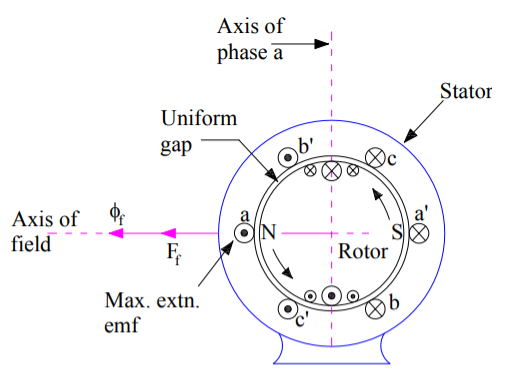
Fig : 3 phase 2 pole alternator
Q6. State and derive equation Synchronous impedance?
Ans:
1. The actual generated voltage consists of the summation of two component voltages. One of these components voltages is the voltage that would be generated if there were no armature reaction.
2. It is the voltage that would be generated because of only field excitation. This component of the generated voltage is called the excitation voltage, Eexc.
3. The other component of the generated voltage is called armature reaction voltage, EAR.
4. This is the voltage that must be added to the excitation voltage to take care of the effect of armature reaction upon the generated voltage.

5. Since armature reaction results, in a voltage effect in circuit caused bu change in flux by current in the same circuit, its effect is of the nature of an inductive reactance .therefore EAR is equivalent to a voltage of inductive reactance and

6. The inductive Reactance XAR is a fictitious reactance which will result in a voltage in armature circuit to account for the effect of armature reaction upon the voltage relations of the armature circuit.
7. Therefore armature reaction voltage can be modelled as in inductor in series with internal generated voltage.
8. In additional to the effect of armature reaction, the stator winding also has a self-inductance and resistance.
Let La = self-inductance of stator winding.
Xa = self-reactance of stator winding.
Ra = armature (stator) resistance.
The terminal voltage V is given by

where
RaIa = armature resistance drop
Xa Ia = armature leakage reactance drop
XAR Ia = armature reaction voltage
9. The armature reaction effect and the leakage flux effect in the machine are both represented by inductive reactance . therefore, it is customary to combine them into a single reactance, is called the synchronous reactance of the machine, Xs.
 …… (4)
 …..(5)


The impedance Zs is called synchronous impedance.
10. The synchronous Reactance Xs is the fictitious reactance employed to account for voltage effects in the armature circuit produced by the actual armature leakage reactance and by the change in air gap flux caused by the armature reaction.
11. Similarly, synchronous impedance Zs is a fictitious impedance employed to account for voltage effects in the armature circuit produced by the actual armature resistance, the actual armature leakage reactance, and the change in air gap flux produced by armature reaction
Q7. State and explain the methods for Determination of Voltage Regulation?
Ans: The following methods are used to determine the voltage regulation of smooth cylindrical rotor type alternators.
A. Direct Load test
B. Indirect methods
A. Direct Load test :
1. The alternator is run at synchronous speed and its terminal voltage is adjusted to its rated value V. the load is varied until the ammeter and wattmeter indicate the rated values at the given power factor.
2. Then the load is removed and the speed and field excitation are kept constant. The open circuit and no load voltage Ea is recorded.
3. The voltage regulation found from percentage voltage regulation. The method of direct loading is suitable only from small alternators of power rating less than kVA.
B. Indirect methods:
For Large alternators, the three indirect methods which are used to predetermine the voltage regulation smooth cylindrical type alternators are as following.
1. Synchronous impedance method or EMF method
2. Ampere turn method or EMF method
3. Zero power factor method or Potier method
Q8. Explain Phasor diagram of a Characteristics of Synchronous Motor?
Ans :
1. The phasor diagram of a Characteristics of Synchronous Motor is shown in fig . The theory of these motors has been developed on the basis of synchronous reactance, which takes care of leakage reactance and armature reaction.
2. A salient pole machine, which has a non-uniform air gap, is described by direct and quadrature axis reactance’s.
3. Variation of the armature current of the motor when its excitation is varied is described by V-curves when the motor develops a given power.
The variation of excitation brings about the following:
- Change in armature current
- Change in line power factor
- Slight change in the load angle.
However, there are minimum and maximum excitations for a given power developed.
4. An increase in the mechanical load at constant excitation would tend to retard the rotor.
5. The angle by which the rotor tends to fall behind the no-load position is called the load angle. In the process of attaining a final position the rotor undergoes oscillations which are damped by damper windings.
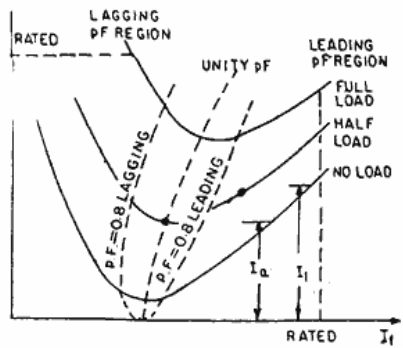
Fig : V curve graph
Q9. State and explain with diagram V- curves?
Ans:
1. V curve is a plot of the stator current versus field current for different constant loads. The Graph plotted between the armatures current Ia and field current If at no load the curve is obtained known as V Curve.
2. Since the shape of these curves is similar to the letter “V”, thus they are called V curve of synchronous motor.
3. The power factor of the synchronous motor can be controlled by varying the field current If.
4. As we know that the armature current Ia changes with the change in the field current If.
5. Let us assume that the motor is running at NO load. If the field current is increased from this small value, the armature current Ia decreases until the armature current becomes minimum.
6. At this minimum point, the motor is operating at unity power factor. The motor operates at lagging power factor until it reaches up to this point of operation.
7. If now, the field current is increased further, the armature current increases and the motor start operating as a leading power factor. The graph drawn between armature current and field current is known as V curve. If this procedure is repeated for various increased loads, a family of curves is obtained.
The V curves of a synchronous motor are shown below.

Fig : V curves of synchronous motor
8. The point at which the unity power factor occurs is at the point where the armature current is minimum.
9. The curve connecting the lowest points of all the V curves for various power levels is called the Unity Power Factor Compounding Curve. The compounding curves for 0.8 power factor lagging and 0.8 power factor leading are shown in the figure above by a red dotted line.
10. The loci of constant power factor points on the V curves are called Compounding Curves. It shows the manner in which the field current should be varied in order to maintain constant power factor under changing load.
11. Points on the right and left of the unity power factor corresponds to the over excitation and leading current and under excitation and lagging current respectively.
12. The V curves are useful in adjusting the field current. Increasing the field current If beyond the level for minimum armature current results in leading power factor.
13. Similarly decreasing the field current below the minimum armature current result results in lagging power factor. It is seen that the field current for unity power factor at full load is more than the field current for unity power factor at no load.
Q10. State and explain two reaction theory of salient pole machine?
Ans :
1. The theory proposes to resolve the given armature MMFs into two mutually perpendicular components, with one located along the axis of the rotor of the salient pole. It is known as the direct axis or d axis component.
2. The other component is located perpendicular to the axis of the rotor salient pole. It is known as the quadrature axis or q axis component.
3. The d axis component of the armature MMF Fa is denoted by Fd and the q axis component by Fq. The component Fd is either magnetizing or demagnetizing.
4. The component Fq results in a cross-magnetizing effect. If Ψ is the angle between the armature current Ia and the excitation voltage Ef and Fa is the amplitude of the armature MMF, then


- Salient Pole Synchronous Machine Two Reaction Theory:
1. In the cylindrical rotor synchronous machine, the air gap is uniform. The pole structure of the rotor of a salient pole machine makes the air gap highly non-uniform.
2. Consider a 2 pole, salient pole rotor rotating in the anticlockwise direction within a 2 pole stator as shown in the figure below.
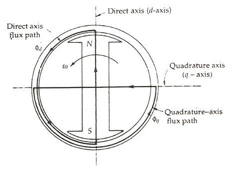
Fig : salient pole rotor rotating anticlockwise in 2 pole stator
3. The axis along the axis of the rotor is called the direct or the d axis. The axis perpendicular to d axis is known as the quadrature or q axis.
4. The direct axis flux path involves two small air gaps and is the path of the minimum reluctance. The path shown in the above figure by ϕq has two large air gaps and is the path of the maximum reluctance.
The rotor flux BR is shown vertically upwards as shown in the figure below.
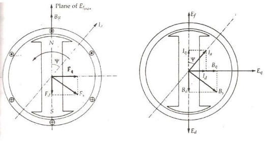
Fig : flux showing diagram( upwards )
5. The rotor flux induces a voltage Ef in the stator. The stator armature current Ia will flow through the synchronous motor when a lagging power factor load is connected it.
6. This stator armature current Ia lags behind the generated voltage Ef by an angle Ψ.
7. The armature current produces stator magneto motive force Fs. This MMF lags behind Ia by angle 90 degrees. The MMF FS produces stator magnetic field BS long the direction of Fs.
8. The stator MMF is resolved into two components, namely the direct axis component Fd and the quadrature axis component Fq.