DATA1: DB 28 ;DECIMAL NUMBER 28
DATA2: DB 1234h ;HEXADECIMAL
DATA3: DB "ABCD" ;ASCII CHARACTER Q4) What is a subroutine ?A4)Subroutine is a group of instructions written separately from the main program to perform function that occurs repeatedly in the main program. When you call a subroutine implementation the current program is stopped and PC is loaded with the memory location of the subroutine running upto RET instruction which marks the end of the subroutine where we produce a return to the main program. The functions of the subroutines are:
- ADD A, 51H
- ADDC A, 75H
- ADD A, @R1
- ADDC A, @R0 CY AC and OV flags will be affected by this operation.
- SUBB A, 51H
- SUBB A, 75H
- SUBB A, @R1
- SUBB A, @R0 CY AC and OV flags will be affected by this operation.
|
|
|
|
|
OY A,#OA5h | A = I0l00I0lb = A5h |
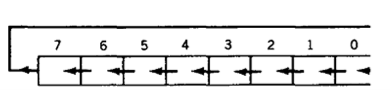
RR A | A = I I0I00I0b = D2h |
RR A | A = 0l I0l00lb = 69h |
RR A | A = I0I l0I00b = B4h |
RR A | A = 0I0l I0I0b = 5Ah |
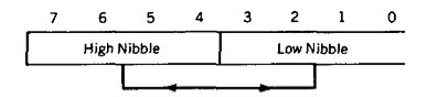
SWAP A | A= I0I00I0lb = A5h |
CLR C | C = 0; A = I0I00I0lb = A5h |
RRC A | C = I; A= 0I0I00I0b = 52h |
RRC A | C = 0; A = l0I0J00lb = A9h |
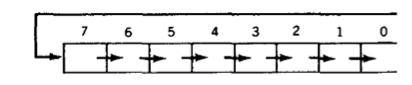
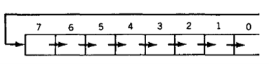
RL A | A= 0I0I00llb = 53h |
RL A | A = I0I00l I0b = A6h |
SWAP A | C = 0; A = 0l 101010b = 6Ah |
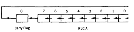
RLC A | C = 0; A = 1 I0I0l00b = D4h |
RLC A | C = l; A= I0I0l000b = A8h |
SWAP A | C = l; A= l000I0I0b = 8Ah |
ORG 0000H ; Set program counter 0000H MOV A,51H ; Load the contents of memory location 51H into A ADD A,55H ; Add the contents of 55H with contents of A MOV 40H,A ; Save the LS byte of the result in location 40H MOV A,52H ; Load the contents of 52H into A ADDC A,56H ; Add the contents of 56H and CY flag with A MOV 41H,A ; Save the second byte of the result in 41H MOV A,#00 ; Load 00H into A ADDC A,#00 ; Add the immediate data 00H and CY to A MOV 42H,A ; Save the MS byte of the result in location 42H END |


