Unit - 1
Introduction
Q1) Explain in details the basic principle of operation of Protective System?
A1) There must be able to discriminate the appropriate disconnecting device. The method of discriminating the faults are two types-
(a) Those which discriminate as to the location of fault.
(b) Type of fault Methods discriminate the type of faults are: The main aim is that the fault section of the system be isolated and in the minimum time.
i) Discrimination by time
Ii) Discrimination by current magnitude
Iii) Discrimination by time and direction
Iv) Discrimination by distance measurement
v) Time as an addition to current magnitude or distance discrimination
Vi) current balance discrimination
Vii) Power direction comparison discrimination
Viii) Phase comparison discrimination
Q2) What is the probability of failure in Power System?
A2) Power systems mainly consist of generator; switch gear, transformer and distribution system. The probability of failure is more on the power system due to their greater length and exposure to atmosphere.
(a) Breakdown at normal voltage may occur on account of: i) The deterioration of insulation (ii) Damage due to unpredictable causes such as perching of birds, accidental short-circuiting by snakes, tree branches, etc.
(b) Breakdown may occur because of abnormal voltages: This may happen because of (i) switching surges (ii) surges caused by lightning. The present practice is to provide a high insulation level of the order 3 to 5 times the normal voltage, but still: (i) The pollution on an insulator string caused by deposited soot or cement dust in industrial area. (ii) Salt deposited wind borne see spray in coastal area. These will initially lower the insulation resistances and causes a small leakage current to be diverted, thus hastening the deterioration. Secondly, even if the insulation is enclosed, such as sheathed and armoured, the deterioration of the insulation occurs because of: (a) Ageing (b) Void formation in the insulation compound of underground cable due to unequal expansion and contractions caused by the rise and fall of temperature. Thirdly, insulation may be subjected to transient over voltages because of switching operation.
Q3) What is a Circuit Breaker? Describe its working principle.
A3) A circuit breaker can make or break a circuit either manually or automatically under all conditions viz., no-load, full-load and short-circuit conditions. This characteristic of the Circuit Breakers Definition has made it a very useful equipment for switching and protection of various parts of the power system.
A Circuit Breakers Definition is a piece of equipment which can-
- Make or break a circuit either manually or by remote control under normal conditions
- Break a circuit automatically under fault conditions
- Make a circuit either manually or by remote control under faith conditions
Thus, a circuit breaker incorporates manual (or remote control) as well as automatic control for switching functions. The latter control employs relays and operates only under fault conditions.
Operating principle:
A Circuit Breakers Definition essentially consists of fixed and moving contacts, called electrodes. Under normal operating conditions, these contacts remain closed and will not open automatically until and unless the system becomes faulty. Of course, the contacts can be opened manually or by remote control whenever desired. When a fault occurs on any part of the system, the trip coils of the circuit breaker get energised and the moving contacts are pulled apart by some mechanism, thus opening the circuit.
When the contacts of a circuit breaker are separated under fault conditions, an arc is struck between them. The current is thus able to continue until the discharge ceases. The production of arc not only delays the current interruption process but it also generates enormous heat which may cause damage to the system or to the circuit breaker itself. Therefore, the main problem in a Circuit Breakers Definition into extinguish the arc within the shortest possible time so that heat generated by it may not reach a dangerous value.
Q4) Write short notes on Voltage Transformers.
A4) Voltage Transformers- It is not possible to connect the voltage coils of the protective device directly to the system in case of high voltage systems. So, it is necessary to step down the voltage, also to insulate the protective equipment from primary circuit. This is achieved by using a voltage transformer. Also known as potential transformer (PTs) which is similar to a power transformer. The voltage transformer is rated in terms of the maximum burden (VA) output it delivers without exceeding specified limits of errors. Whereas the power transformer is rated by the secondary output it delivers without exceeding a specified temperature rise. The output of PTs is usually limited to a few hundred-volt amperes and the secondary voltage is usually 110V between phases. Ideally a VT should produce a secondary voltage exactly proportion al to the primary voltage and exactly in phase opposition. This cannot Power System Protection 16 obviously be achieved in practice owing to the voltage drops in the primary and secondary coil due to the magnitude and power factor of the secondary burden. Thus, ratio errors and phase angle errors are introduced. There are two types of Voltage devices a) The conventional wound type voltage transformers up to (132kV) b) Capacitor Voltage Transformer (>132 kV) When Appreciable current flows in the burden both ratio and phase are introduced because of the load current flowing through the capacitor C1. The voltage drops on load due to reluctance of the capacitors can be compensated by inserting an inductance reactance in series with the load.
Q5) What is the need of Protective System Schemes?
A5) The objective of power system protection is to isolate a faulty section of electrical power system from rest of the live system so that the rest portion can function satisfactorily without any severe damage due to fault current.
Actually circuit breaker isolates the faulty system from rest of the healthy system and these circuit breakers automatically open during fault condition due to its trip signal which comes from protection relay. The main philosophy about protection is that no protection of power system can prevent the flow of fault current through the system, it only can prevent the continuation of flowing of fault current by quickly disconnect the short circuit path from the system.
Q6) Write short notes on Current Transformers.
A6) Current Transformer (CT)-High magnitude primary current are reduce to a value suitable for relay operation to a value suitable for relay operation with the help of current transformers (CTs). (Then CTs provide current in the relay which are proportional to those in primary.) The primary winding of the CTs is connected in series whit the load and carries the actual power system current (normal or fault). The secondary is connected to the measuring circuit or the relay. The working range of a protective CT extends over the full range between the ankle and the knee points and beyond. Whereas the measuring CT usually operate in region of ankle point. Measuring CTs require comparatively high accuracy over the range of 10% to 120% of rated. Grain oriented steels having high saturation level are used as core materials for protective CTs and nickel iron alloys having low exciting ampere turn per unit length of the core used for measuring CTs. It is common practice to use 1A secondary rating CTs. The secondary of the bus bar primary CT is usually about 1500 secondary turn. When rated primary currents much in excess of 1500 A are encountered then the main bar CTs with rated secondary current of 5A and 10A along with auxiliary CTs of 5/1 or 10/1 respectively are used.
Q7) Define Feeder Protection.
A7) Feeder protection is defined as the protection of the feeder from the fault so that the power grid continues supply the energy. The feeder injects the electrical energy from the substation to the load end. So, it is essential to protect the feeder from the various type of fault. The main requirements of the feeder protection are;
- During the short circuit, the circuit breaker nearest to the fault should open and all other circuit breakers remain in a closed position.
- If the breaker nearest to the fault fails to open then, backup protection should be provided by the adjacent circuit breaker.
- The relay operating time should be small to maintain the system stability without necessary tripping of a circuit.
Q8) Write short notes on equation for Electromagnetic Relays.
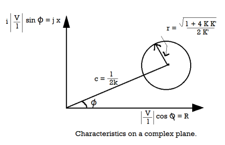
A8) When not more than two quantities are involved, the equation for the characteristic of the relay at the threshold of operation under steady state conditions, when plotted on complex planes is a circle. The General Equation for Electromagnetic Relay can be represented in a general form as-

Where, |A| & |B| are two quantities being compared
 = Electrical Angle between A & B
 = Relay characteristic angle, which is the value of
  for maximum torque
K & K’ = Scalar Constants
K’’ = Mechanical restraining toque
If the two input quantities are current I and voltage V then the equation for threshold operation becomes:

Which can also be explained as: the current winding produces a torque KI2 and the potential winding a torque K’V2, while the torque due to interaction of current and potential windings will be VI cos (Φ-θ).
K” is finite only in singe quantity relays, where it is used as a level indicator; it is made negligibly small in relays with more than one input so K” = 0 and dividing throughout by K′ |I|2


It can be represented as a circle on a complex plane, having

As coordinates, i.e., on the R-X plane as shown in the figure below
Q9) Explain Overlapping Zone of Power System.
A9) If there were no overlapping in the protective zone, then the failure occurs in the equipment will not lie in any one of the zones and hence no circuit breaker would be tripped. The fault occurs in the unprotective system will damage the equipment and hence disturb the continuity of the supply.
The figure below shows a certain amount of overlapping between the protective zones.
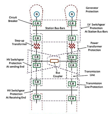
The probability of failure in the overlap region is very small. But the overlap region will cause the tripping of the more circuit breaker than the minimum necessary for the disconnection of the fault’s region. Because when the fault occurs in any one of the two overlapping regions than the breaker of both the region will be opened, and the systems are isolated.
Q10) List the basic attributes of Power System Protection and explain any two.
A10) Every protective system which isolates a faulty element must satisfy four basics
Requirements:
1. Reliability
2. Selectivity
3. Fastness of operation
4. Discrimination
Reliability
Reliability is a qualitative term. It can be expressed as a probability of failure.
- Quality of personnel i.e., mistakes by personnel are most likely causes of failure.
- High contact pressure
- Dust free enclosures
Records show that the order of likelihood of failure is relays, breakers, wiring, current transformers, voltage transformers and battery. When relays using transistors are considered, the failure rate goes up still further.
Selectivity
The property by which only the faulty element of the system is isolated and the remaining healthy sections are left intact. Selectivity is absolute if the protection responds only to faults within its own zone and relative if it is obtained by grading the setting of protections of several zones which may respond to a given fault.
Q11) What are the components of Protection System?
A11) Some of the commonly used components of the protective schemes are:
- Relays
- Circuit Breakers
- Tripping and Auxiliary Supplies
- Current Transformers
- Voltage Transformers
Q12) What are the different classification of Relay?
A12) The actuating quantity is normally in electrical signal. Sometimes the actuating quantity may be pressure and temp. Protective relay can be classified as
- According to the function in protection scheme.
- According to the nature of actuating quantity.
- According to the connection of the sensing element
- According to the method by which the relay acts upon the circuit breaker
Generally, the electrical protective relays can be broadly classified in two categories
(a) Electromagnetic relays- Electromagnetic relays are those relays which are operated by electromagnetic action. Modern electrical protection relays are mainly microprocessor based, but still electromagnetic relay holds its place. It will take much longer time to be replaced the all electromagnetic relays by microprocessor based static relays. So before going through detail of protection relay system we should review the various types of electromagnetic relays.
(b) Static relays- A relay in which the measurement or comparison of electrical quantities are done in a static network. The output signal operates a tripping device which may be electronic, semiconductor or electromagnetic. The static relays are classified according to the types of measuring units or the comparator 1) Electronic relays 2) Transducer (magnetic amplifier relay) 3) Rectifier bridge relay 4) Transistor relay 5) Hall effect relay 6) Gauss effect relay.
Q13) Explain in detail the relay design & its construction?
A13) The design of protective relay is normally divided into the following stages:
(a) Selection of the operating characteristics
(b) Selection of proper construction
(c) Design of the contact moment from the point of view of utmost reliability.
The relay operating characteristic must match with the abnormal operating characteristics of the system i.e., it should clearly show the conditions for tripping under various abnormal operating conditions. The most important considerations in the design for construction are:
- Reliability
- Simplicity of construction
- Circuitry
The construction of the relay is divided into the following:
- Contacts- Contact performance is probably the most important item affecting reliability of the relay. Corrosion or dust deposit can cause non-operation of relay. Thus, material and shape of relay are of considerable importance. A good contact system design provides restricted contact resistance, reduced contact wear. The contact material used is gold, gold alloy, platinum, palladium and silver. The selection of the contact material depends on a number of factors like:
(a) The voltage per contact break
(b) The current to break
(c) The type of atmospheric pollution under which the contacts are operate
The following factors are to be considered for selecting a suitable contact material: 1) The nature of the current to be interrupted (ac or dc) 2) Voltage at break and make operation 3) Value of current magnitude 4) Frequency of operation 5) The actual speed of contact at make or break 6) Contact shape
- Bearing-
(a) Single ball bearing
(b) Multi ball bearing
(c) Pivot and jewel bearing – This is the most common type for precision relay
- Electromechanical design- It consists of the design of the magnetic circuit and the mechanical features of core, yoke, and armature. The reluctance of the magnetic path is kept to a minimum by enlarging the pole face which makes the magnetic circuit more efficient.AC electromagnets made from soft iron, low carbon steel core having a slot for mounting shaded rings are more common. The relay coil current is usually limited to 5A and the coil voltage to 220 V but the insulation for the relay coil is designed to withstand at least 4kV.The relay coil is designed to carry about 15 times the normal current foe one second.
Termination & housing- Material used for springs are stainless steel; nickel steel, phosphorous bronze and Beryllium copper. The spring is insulated from the armature by molded blocks. For moulded blocks nylon is used.
Q14) Explain the theory of Induction Relay Torque?
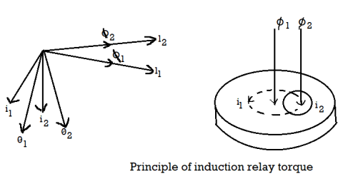
A14) In Induction Relay Torque Equation, two magnetic fluxes Φ1 and Φ2 differing in time phase penetrate through a disc. These alternating fluxes induce emfs e1 and e2 in the disc which lag their respective fluxes by 90°. These emfs lead to the flow of eddy currents i1 and i2. By the interaction of Φ1 with i2 and Φ2 with i1 a driving torque is produced.
The currents i1 and i2 lag the voltages e1 and e2 by the impedance angle λ of the disc. Below figure shows the vector diagram.
Let,


Therefore, the resultant torque is given as-


Thus, the induction relay is a sine comparator in which the maximum torque is developed when α is 90° or 270° and zero torque when α is 0° or 180°.
Q15) Explain the different type of Electromagnetic Relays?
A15) Depending upon working principle the electromagnetic relays can be divided into following types of electromagnetic relays.
- Attraction Armature Type Relay
This has four types i.e., plunger, hinged armature, balanced beam and moving iron polarized. These are the simplest types which responds to AC and DC.
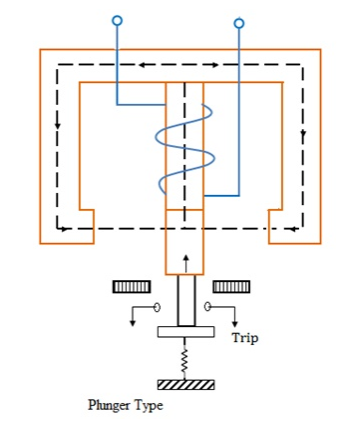
The force of attraction is given by-


Where K is a constant &  is pulsating
The coil is energized by current or voltage, a proportionate operating quantity, which produces a magnetic flux, thereby creating an electromagnetic force. This force is proportional to the square of the flux in the air gap or square of the current. This force increases, as the armature approaches the pole of electromagnet. This type of relay is used for protection of small machines and also used for auxiliary relays such as indicating relays (flags) alarm and annunciator relays etc.
Ii. Induction Disc Type Relay
- Watt Meter Type or Non-Directional Relay- It has a metallic disc free to rotate between the poles of two electro magnets. The spindle of this disc carries a moving contact which bridges two fixed contacts when the disc rotates through an angle, which is adjustable between 0o to 360o. By adjusting this angle, the travel of moving contact can be adjusted so that the relay can be given any desired time setting which is indicated by a pointer. The dial is calibrated from 0-1. The relay time from name plate cure is to be multiplied by time multiplier setting.
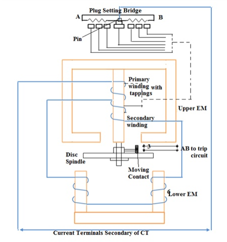
The upper magnet has two windings. The primary coil is connected to the secondary of CT through tappings in it. These tappings are connected to plug Settings Bridge. The secondary is connected to the lower electro magnet. The torque exerted on the disc is due to the interaction of eddy current produced therein by the flux from the upper EM and the lower EM. The relay setting is 50% to 200% in steps of 25%.
b. Shaded Pole Type or Non-Directional Relay
The rotating disc is made of aluminum. In the above type one half of each of electromagnet shown in fig, is surrounded by a copper band called as the shading ring. The shaded portion of the pole products a flux which is displaced in space and time w.r.t the flux produced by the unshaded portion of the pole. These two alternating fluxes cut the disc and produce eddy currents in it. Torques are produced by the interaction of each flux with the eddy current produced by the other flux. The resultant torque causes the disc to rotate.
A spring is used to supply the resetting torque. A permanent magnet is employed to produce eddy current braking to the disc. The braking torque is proportional to the speed of the disc. When the operating current exceeds pick-up value, driving torque is produced and the disc accelerates to a speed where the braking torque balances the driving torque. The disc rotates at a speed proportional to the driving torque.
At a current below the pick-up value, the disc remains stationary by the tension of the control spring acting against the normal direction of disc rotation. The disc rests against a backstop. The position of the back-stop is adjustable. So that the relay-contacts travel distance can be varied according to need. This is called time-setting of the relay.
Iii. Induction Cup Type Relay
It is a double actuating quantity relay (current & voltage) which is highly sensitive, high speed, steady & non-vibrating torque and ration of re-set to pickup is high (above 95%) as well as it has operating time less than 0.01 seconds.
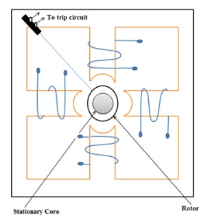
The operating is similar to induction motor. It consists of a stationary rotor iron core and moving rotor conductor (cup). The moving element is a hollow cylinder or cup which turns on its axis. The driving element is a four or eight pole structure placed radially around the outside of the cylinder and joined by a yoke. To shorten the air-gap, a stationary iron core is placed inside the rotate cylinder.
It is a high-speed induction relay since inertia is less. The two pairs of coils are displaced by 90o. When these coils are excited, a rotating magnetic field is produced. The rotor cuts the magnetic field and an emf is induced in the rotor. Which results in a current due to short circuit nature of the rotor. A torque is produced due to the interaction between the rotating flux and the induced current which causes the rotation of the cylinder. The movement of the rotor closes the trip circuit. The torque produced is proportional to |I1||I2| sin α or Φ1 Φ2 sin α, where Φ1 Φ2 are the fluxes due to excitation currents I1 and I2 of coil pairs and α is the phase difference between the two fluxes.
Iv. Balanced Beam Relay
All these relays have the same principle. That is electromagnetic force produced by the magnetic flux which in turn is produced by the operating quantity. The force exerted on the moving element is proportional to the square of the flux in the air gap or square of the current. In DC electromagnetic relays this force is constant. If this force exceeds the restraining force, the relay operates.
This type of balanced beam relay has a fixed beam and an electromagnet (EM) as shown in the figure. The EM has two windings, one is energized by the voltage and the other energized by the current. Under normal conditions, the pull due to the voltage (restraint quantity) will be high and hence the contact remains open. When a fault occurs, the current increases, the pull due to current will be more than the pull due to voltage. This closes the contacts of the trip circuit.
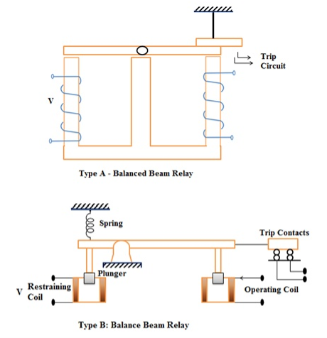
This balanced beam type relay shown in the figure consists of a horizontal beam pivoted centrally, with one armature attached to either side. There are two coils, one on each side. The beam remains horizontal till the operating force becomes greater than the restraining force. Current in coil gives the operating force and in the other, the restraining force. When the operating force or torque increases, the beam tilts and then the contact closes. The relay then actuates the tripping mechanism of the circuit breaker controlling the line / equipment.
v. Moving Coil Relays
It is of two types
- Rotary Moving Coil
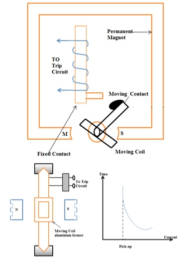
It consists of a permanent magnet coil wound on a non-magnetic former, spring, spindle etc. as shown in the fig. The coil is energized by the fault current. Due to the interaction of the permanent magnetic field and the field due to the coil, moving torque is developed. Due to this the spindle rotates and closes the trip circuits. It has negative time-current characteristics as shown in the figure. It has high torque / weight ration.
F α NHIL
Where F = Force, N= No. Of turns, H=Magnetic Field, I=Current in the coil, L=Length of coil
b. Axial Moving Coil
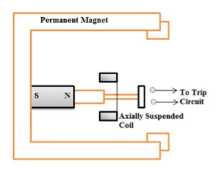
It has axially suspended coil wound on a former. The coil has only axial movement. When the coil is energized by the current, magnetic field is developed and this magnetic field is repelled by the already existing permanent magnet. Due to this, contacts get closed.
This relay is more sensitive and faster than the rotary moving coil relay. This relay has inverse operating time-current characteristics.
Q16) What are the basic elements of Static Relays?
A16) The static relay is the combination of both the static and the electromagnetic relay. In this relay, there is no armature and moving contacts and response is developed by the components without mechanical motion. The solid-state components used are transistors, diodes, resistors, 0and capacitor and so on. In the static relay, the measurement is performed by electronic, magnetic, optical or another component without mechanical motion.
Static relay consists of the following functional circuits:
- Input stage with CT’s and PT’s:
The input to the relay is obtained from the CT/PT. This output of CT/PT is given to the auxiliary CT/PT. The input stage has CT’s and PT’s, summation units, auxiliary CT’s and PT’s, filter.
- Rectifiers and smoothing circuits:
In these circuits, the input given from auxiliary CT/PT is given to the single bridge rectifier to rectify the fluctuating quantities. This rectifier output is then smoothened to avoid any ripples and is provided it to a level detector which levels the quantities.
- Comparator:
The output which is smoothened is given to the comparator to compare it with a fixed input. Thus, the output is then fed to the measuring unit. The comparators used are of amplitude, hybrid and phase comparators.
- Measuring unit:
If the input of the comparator is above the threshold value, then the level detector gives an output otherwise it doesn’t produce output if it’s below the threshold value.
There are amplifiers, logic circuits as well as level detector circuits to complete the job.
- Output stage:
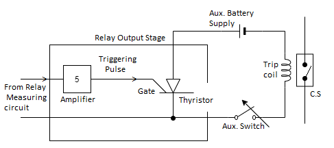
The output of the level detector is then fed to the output stage of the relay in which it has a PMMC (Permanent magnet moving coil) relay, a Thyristor in series with the trip coil and auxiliary switch.
Whenever there is a fault the relay operates, and it gives gate signal to the Thyristor which then energizes the trip coil so that the circuit breaker contacts get open and the circuit is tripped. These relays do not have any arcing problems as all the entire relay system is static.
Q17) Discuss the Advantages & Disadvantages of Circuit Breakers.
A17) The advantages & disadvantages of CB are discussed below:
Advantages of CB
- It protects from damage caused by flow of excessive current.
- It is are more reliable.
- It can be reset as it operates via a switch.
- It is very sensitive in operation
- It has the facility of frequent operation.
- High insulation facility
- Respond quicker than fuses
Disadvantages of CB
- Installation & repair is expensive
- Circuit breakers won't react as quickly as a fuse in power surges. This means it would be possible that electronics connected to the circuit could be damaged by energy that is just let through