Unit - 2
Faults and Over-Current Protection
Q1) How are faults analyzed in a power system?
A1) The faults in the power system are analyzed by making use of Thevenin’s theorem about the point of fault location. The theorem is important as it can determine the changes in currents and voltages of a linear network when additional impedance is added between two nodes of the network. To determine the distribution in current and voltage in the system, the distribution in each of the sequence networks must be determined. The Thevenin’s equivalents of positive, negative and zero sequence networks are equivalent to those of the networks for a single generator. Considering the system given below, it is needed to find the Thevenin equivalent network for determining the positive, negative and zero sequence networks about the point P.
The Thevenin equivalent of the positive sequence network is obtained from the positive sequence network. The Thevenin equivalent voltage source is the prefault voltage at the fault point P and the equivalent impedance Z1eq is the impedance as seen between the fault point and the zero potential bus shorting the voltage sources. Similarly, the Thevenin equivalent negative and zero sequence networks are obtained from the negative and zero sequence networks respectively. Since the system is balanced, no negative or zero sequence currents are flowing before the fault occurs. Hence the prefault voltage of both negative and zero sequence are equal to zero.
Q2) What can be the reasons for weakening of Insulation?
A2) The weakening of insulation may be due to one or more reasons and they are listed below:
- Ageing
- Temperature
- Rain, hail, snow
- Chemical pollution
- Foreign objects
- Other causes
Q3) What are the effects of faults on the power system?
A3) Faults causes heavy currents to flow. If these fault currents persist even for a short time, they will cause extensive damage to the equipment that carry these currents. Over-currents cause overheating and hence there is a threat of fire. Overheating also causes deterioration of the insulation, thus weakening it further.
Also, excessive mechanical forces develop due to over-currents which causes mechanical damage. Transformers suffer mechanical damage to their windings, due to faults. This is due to the fact that any two current-carrying conductors experience a force. This force goes out of bounds during faults, causing mechanical distortion and damage.
The mechanical power input remains substantially constant at its pre-fault value. The presence of faults causes the alternator to accelerate. The rotor angle  starts increasing. Thus, the alternators start swinging with respect to each other. If the swing goes out of control, the alternators will have to be tripped out. Thus, in an interconnected power system, the system stability is at stake.
Q4) What are the different kind of faults in the power system and which one is the most severe?
A4) L-G Fault
L-L Fault
LLG Fault
LLL Fault
The most severe is the LLL Fault.
Q5) Explain Single Line to ground fault without Zf.
A5) The system to be analyzed is given below. If there is a line-to-ground fault at phase a, the boundary conditions are-


The sequence network equations are:


The solution of these six equations will give all the six sequence components of voltage and current. From the sequence current equations:


Substituting the values of Ib & Ic in the above equations:

Similarly, according to symmetrical component of voltage:

Substituting the values of sequence voltages from the sequence network equation,

Since, 
The above equation becomes-


From the above equation it is evident that to simulate an L-G fault all the three sequence networks are required, and all these sequence networks are to be connected in series, as the sequence currents are equal in magnitude and phase. The interconnection is shown in the figure below-

Q6) Explain Single Line to ground fault with Zf.
A6) Line to Ground Fault with Zf
When the fault impedance and the neutral impedance are included, the analysis of the single line to ground fault can be analyzed as follows. The boundary conditions are-


From the above equations, the sequence components can be derived as


The fault diagram and the interconnection are given below:
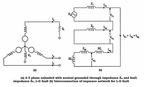
Q7) Explain what are sequence networks in Power systems.
A7) The sequence impedance network is defined as a balance equivalent network for the balance power system under an imagined working condition so that only single sequence component of voltage and current is present in the system. The symmetrical components are useful for computing the unsymmetrical fault at different points of a power system network. The positive sequence network determines the load flow studies in power system.
Every power system has three sequence network (positive, negative and zero sequence networks) and these networks carrying three sequence current. These sequence currents interconnect in different ways to represent a different unbalance fault condition. These sequence current and voltage are calculated during the fault due to which actual current and voltage can be determined.
Q8) Explain in detail about Sequence Impedance?
A8) Sequence Impedance
Like the symmetrical components for the current, voltage and power, the impedances are also composed of symmetrical components known as the sequence impedances. These can be defined as follows: The positive sequence impedance of equipment is the impedance offered by the equipment to the flow of positive sequence impedance. Similarly, the negative and zero sequence impedance of the equipment is the impedance offered by the equipment to the flow of corresponding sequence currents.
Measurement of positive sequence impedance: The positive sequence impedance depends upon the working of the machine, i.e., whether it is working under sub transient, transient or steady state condition. The impedance measured under steady state is known as synchronous impedance and is measured by the well-known open circuit and short circuit test. The impedance is defined as
Synchronous impedance in p.u

Method of test for synchronous Impedance: The machine here is run at a proper direction with the help of a prime mover. The shorting link switch is kept in off position to perform open circuit test and noted the readings of the voltmeter by varying the field current. Similarly, the short circuit test is done by putting the shorting switch on and noting the readings of armature current with the variation of the field current.

Measurement of Negative sequence Reactance: It is the impedance offered to the flow of negative sequence current.
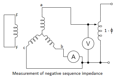
The machine here is driven at rated speed, and a reduced voltage is applied till the rated current flows in the armature. When there is a flow of negative sequence current there may be a possibility of hunting which would cause the pointer to deflect. This allows the mean reading to be taken. The negative sequence impedance is given by

Where V is the voltmeter and I is the ammeter reading.
Measurement of zero sequence impedance: Zero sequence impedance is the impedance offered by the machine to the flow of zero sequence current. This impedance depends on the distribution of the windings on the factors like pitch and breadth factors. The value is much smaller as compared to zero and negative sequences.
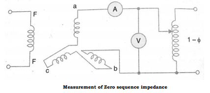
The machine is at standstill and a reduced voltage is applied. The zero-sequence impedance is-

Q9) What are Over Current Relays?
A9) In an over current relay or o/c relay the actuating quantity is only current. There is only one current operated element in the relay, no voltage coil etc. are required to construct this protective relay.
In an over current relay, there would be essentially a current coil. When normal current flows through this coil, the magnetic effect generated by the coil is not sufficient to move the moving element of the relay, as in this condition the restraining force is greater than deflecting force. But when the current through the coil increases, the magnetic effect increases, and after a certain level of current, the deflecting force generated by the magnetic effect of the coil, crosses the restraining force. As a result, the moving element starts moving to change the contact position in the relay. Although there are different types of over current relays but basic working principle of over current relay is more or less same for all.
Q10) Explain some different types of Over Current Relays?
A10) Types of Over Current Relays
(i) Instantaneous Over Current Relay
Construction and working principle of instantaneous over current relay is quite simple.
Here generally a magnetic core is wound by a current coil. A piece of iron is so fitted by hinge support and restraining spring in the relay, that when there is not sufficient current in the coil, the NO contacts remain open. When the current in the coil crosses a preset value, the attractive force becomes enough to pull the iron piece towards the magnetic core, and consequently, the no contacts get closed.

We refer the pre-set value of current in the relay coil as pickup setting current. This relay is referred as instantaneous over current relay, as ideally, the relay operates as soon as the current in the coil gets higher than pick upsetting current. There is no intentional time delay applied. But there is always an inherent time delay which we cannot avoid practically. In practice, the operating time of an instantaneous relay is of the order of a few milliseconds.
(ii) Definite Time Over Current Relay
This relay is created by applying intentional time delay after crossing pick up the value of the current. A definite time overcurrent relay can be adjusted to issue a trip output at an exact amount of time after it picks up. Thus, it has a time setting adjustment and pickup adjustment.
(iii) Inverse Time Over Current Relay
Inverse time is a natural character of any induction type rotating device. Here, the speed of rotation of rotating part of the device is faster if the input current is more. In other words, time of operation inversely varies with input current. This natural characteristic of electromechanical induction disc relay is very suitable for overcurrent protection. If the fault is severe, it will clear the fault faster. Although time inverse characteristic is inherent to electromechanical induction disc relay, the same characteristic can be achieved in microprocessor-based relay also by proper programming.
Q11) Explain Current Protection Scheme?
A11) Current protection schemes are integrated into power system designs to protect the power system components from the excessive withdrawal of current and short circuit currents. Excessive over-currents could occur on many different power system components such as motors causing hazards if not cleared within the safe time frame.
Short-circuit currents are undesired currents that occur in electrical circuits and flow along paths, which have low impedances (almost zero) causing severe hazards. There are different types of current protection schemes such as overcurrent, undercurrent and phase-sequence. However, overcurrent protection is also sub-classified into other categories such as non-directional overcurrent, directional overcurrent and voltage-dependent overcurrent.
Overcurrent protections follow 19 well-defined time characteristic curves, which define the time delay before the tripping angle as a function of the current. The curves are divided according to standard into IEC and ANSI, and the most popular of these curves are the definite time curve (DT), the extremely long inverse time (ET), the very long inverse time curve and the normal inverse time curve.

Q12) Explain the Zones of Protection in detail?
A12) An electric power system is divided into several zones of protection. Each zone of protection contains one or more components of a power system in addition to two circuit breakers. When a fault occurs within the boundary of a particular zone, then the protection system responsible for the protection of the zone acts to isolate (by tripping the Circuit Breakers) every equipment within that zone from the rest of the system. The circuit Breakers are inserted between the component of the zone and the rest of the power system. Thus, the location of the circuit breaker helps to define the boundaries of the zones of protection. Different neighboring zones of protection are made to overlap each other, which ensure that no part of the power system remains without protection. However, occurrence of the fault with in the overlapped region will initiate a tripping sequence of different circuit breakers so that the minimum necessary to disconnect the faulty element.
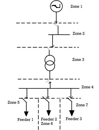
Following six categories of protection zones are possible in a system; we apply here a concept of selective coordination.
- Generators and generator–transformer units
- Transformers
- Buses
- Lines (transmission, sub-transmission, and distribution)
- Utilization equipment (motors, static loads, or other)
- Capacitor or reactor banks (when separately protected).
Q13) Explain the Backup Protection Scheme?
A13) Back-up protection is the name given to a protection which backs the primary protection whenever the later fails in operation. The back-up protection by definition is slower than the primary protection system. The design of the back-up protection needs to be coordinated with the design of the primary protection and essentially it is the second line of defence after the primary protection system.
Relays backup protection: Single circuit breaker is used to for both primary and backup relays. Breaker Backup protection: Separate circuit breakers is used for both protections in the same station. Remote backup protection: one breaker for primary protection in one station and then another breaker for backup protection in another station.
Example: Consider the remote backup protection is provided by a small-time graded relay, as shown in the figure below. Let F be the fault occur on relay R4. The relay R4 operates the circuit breaker at D and isolate the faulty section. Now if the circuit breaker D fails to operate, the faulty section would be isolated by the operation of the relay R3 at C.

The use of the backup protection depends on the economics and technical consideration. The backup protection usually for the economic reason not so fast as the main protection.
Q14) How are Over Current Relay helpful in Feeder Protection?
A14) Over Current relay for Feeder Protection
It is customary to have two elements of over current and one element of earth fault protection system in the most elementary form of protection of three phase feeders. Different types of feeders employ the over current protection along with the directional relay so that proper discrimination of an internal fault is possible. Some examples are illustrated below.
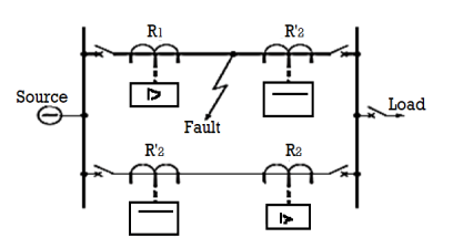
(a) Application of directional relays to parallel feeders
It may be seen from the below given parallel feeders that the relays placed at the load side of both the lines use directional element which respond to a direction away from the bus bars. Similarly, the relays placed at the source side do not require any directional element.
(b) Application of directional relays to ring mains
A similar concept of discrimination is also utilized in the below given ring main feeder and a feeder fed from both the sides. It can be observed that relays placed near the bus connecting the sources, don’t have any directional feature, whereas the rest of the buses, respond to a direction always away from the source. It is good practice to locate a fault anywhere among different sections of the feeders and check whether that particular section only is isolated without disrupting the power flow in other sections.
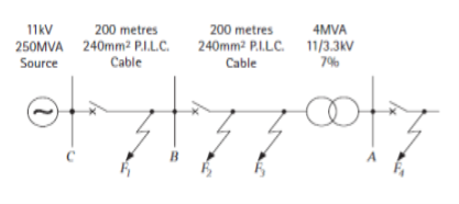
(c) Over current protection radial system
Q15) Write short notes on Equation for Comparators?
A15) Equation for Comparators
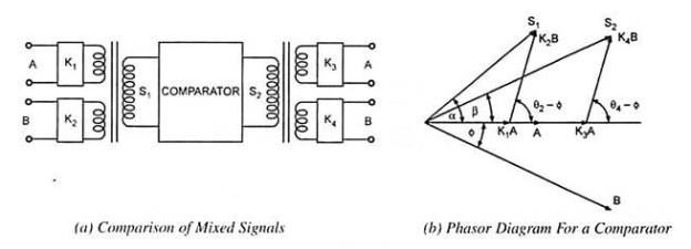
Let us first derive the general threshold equation assuming that there are two input signals S1 and S2 such that when the phase relationship or magnitude relationship fulfills pre-determined threshold conditions, tripping is initiated. The input signals are derived from the system through instrument transformers (CTs and/or PTs). In case the two quantities to be compared are different (i.e., voltage and current), some form of mixing device, such as current voltage transactor, is required.
Let the two input signals be represented as –


Where, A and B are the primary system quantities, K1 and K3 are the scalar numbers and |K2|and | K4| are the complex numbers with angles θ2 and θ4 respectively. Taking A as the reference phasor and phasor B to lag A by an angle ɸ. Then the above equation can be rewritten as –


Q16) Describe the Primary Protection Scheme with causes of failure?
A16) The primary protection scheme ensures fast and selective clearing of any fault within the boundaries of the circuit element, that the zone is required to protect. Primary Protection as a rule is provided for each section of an electrical installation. However, the primary protection may fail. The primary cause of failure of the Primary Protection system is enumerated below.
1. Current or voltage supply to the relay.
2. D.C. Tripping voltage supply
3. Protective relays
4. Tripping circuit
5. Circuit Breaker
Q17) What are the methods of Back-up Protection?
A17) The methods of back-up protection can be classified as follows:
- Relay Back-up: in this method, Different breakers are provided for main and back-up protection, both the breakers being in the same station.
- Breaker Back-up: In this method, separate breakers are provided for primary and backup protection. Both the types of breakers are at the same station.
- Remote back-up: In this method, separate breakers are provided for primary and backup protection. The two types of breakers are at the different stations and are completely isolated and independent of each other.
- Centrally Coordinated Back-up:
- The system having central control can be provided with centrally controlled back-up. Central control continuously supervises the load flow and frequency in the system. The information about load flow and frequency is assessed continuously.
- If one of the components in any part of the-system fails, (e.g., a fault on a transformer, in some station) the load flow in the system is affected. The central coordinating station receives information about the abnormal condition through high frequency carrier signals.
- The stored programme in the digital computer determines the correct switching operation, as regards severity of fault, system stability.
Q18) Determine the PSM (plug setting multiplier) of a 5A, 2.2 sec over current relay having a plug setting Ps=200%. The supply CT is rated 400:5A and the fault current is 12000A.
A18)


On PS of 200%
The relay current
Hence PSM 
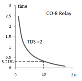
Q19) For the relay R1 in the system shown determine the current tap setting CTS. If the maximum three-phase fault current is 2400A and the TDS=2.0 find the operating time if the relay type is CO-8 (inverse type).

A19)
Load current at the busbar 1

The relay current 
Since the current tap setting (CTS) of CO-8 relay available are 4,5,6,7,8,10 and 12. Hence we choose CTS=4
Fault current 
Relay current during fault
As multiple of selected CTS 
From the CO-8 ch/s curve:
Operating time 
Q20) Determine the time of operation of an IDMTL relay rating 5A, 2.2sec and having a plug setting PS= 125%, and TMS=0.6. It is connected to a supply circuit through a C.T of 400/5 ratio. The fault current is 4000A.
A20)
Since Ps=125%=1.25
Then the operating current of the relay: 5×1.25=6.25A


