Unit - 1
DC Motor Characteristics
Q1) Derive the EMF equation for DC Machines?
A1) It is a mathematical expression to calculate the EMF induced in a DC machine. As you know, the amount of EMF induced in a conductor depends on the number of turns of the coil and the rate of change of flux.
Consider a motor that has ‘P’ number of poles and a ‘Z’ number of conductors per pole spinning at a speed of ‘N’ radials per second.
If ‘φ’ is the flux produced in ‘webers’, according to Faraday’s law, the EMF induced per conductor is given by:

The above equation states that the induced EMF is directly proportional to the change in flux. The flux generated by a DC is constant. The total flux generated by all the poles is given by:

As the machine is spinning at ‘N’ rpm (radials per minute), the time taken for one revolution is given by:

Therefore, the EMF induced per conductor is given by:

The total EMF induced in the machine, if there are ‘Z’ number of conductors and ‘A’ number of parallel paths is:

The above is the EMF equation of DC machines.
Q2) Derive the Torque equation for a DC Machine?
A2) A motor generally drives a load through transmission system. While motor always rotates, the load may rotate or may undergo a translational motion. Load speed may be different from that of motor, and if the load has many parts, their speeds may be different & while some may rotate or go through translational motion. It is convenient to represent the motor to represent the motor load system by equivalent rotational system as shown in the figure below.

Load torque includes friction & windage torque of a motor. Motor-load system can be described by the following fundamental torque equation-

The above equation is applicable to variable inertia drives such as mine winders, reel drives & industrial robots.
For drives with constant inertia, ( =0), therefore,

The above equation shows that the torque developed by motor is counter balanced by a load torque Tl and a dynamic torque  . Torque component is called the dynamic torque because it is present only during transient operations.
Q3) Explain the relationship between Torque-Speed characteristics of Separately excited DC Motor?
A3) Separately Excited DC motor is shown in the below figure.
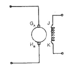
The circuit equation of a Speed Torque Characteristic of Separately Excited DC Motor whose armature, having a total of Z conductors, is wound for 2P poles (the brushes divide the winding into 2a parallel paths) is,

Where E is the back emf of the armature given by

Where ω is the angular velocity given by ω = (2π N/60).
From the above two equations, we get,

The torque developed by the motor is given by,

Substituting for Ia in the above two equations, we get,

When Td = 0 the corresponding speed N0=Va/(KeΦ) is the no-load speed. The motor speed decreases as the torque developed increases, resulting in a drooping characteristic. The speed-torque curves are shown in the figure below. The figure clearly shows a speed drop of 2 to 3% as the torque varies from no-load to full load.
In dc machines the armature mmf reacts with the field mmf this reaction is known as the armature reaction. When the effects of the armature reaction are neglected, the flux per pole of the motor is constant and is independent of load. In normal construction the brushes are placed in the neutral zone. The armature reaction, though cross magnetizing, is followed by demagnetization due to saturation. The effect of demagnetization on the field flux due to armature flux is clearly shown in the figure. The speed drop from no-load to full load decreases, improving speed regulation.
Q4) How does Torque-Speed curve changes with Armature Voltage?
A4) In this method of speed control, armature is supplied from a separate variable DC voltage source, while the field is separately excited with fixed rated voltage as shown in figure. Here the armature resistance and field current are not varied.
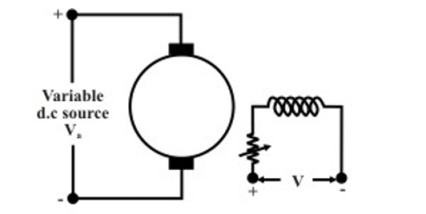
Speed control by controlling armature voltage can be seen in the above figure.
Since the no load speed φ, the speed versus Ia characteristic will shift parallelly as shown in figure for different values of Va.
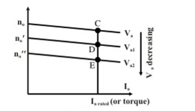
As flux remains constant, this method is suitable for constant torque loads. In a way armature voltage control method is like that of armature resistance control method except that the former one is much superior as no extra power loss takes place in the armature circuit. Armature voltage control method is adopted for controlling speed from base speed down to very small speed as one should not apply across the armature a voltage which is higher than the rated voltage.
Q5) Explain & give examples of load Torque-Speed characteristics?
A5) Speed- Torque Characteristics of various types of loads & drives motors
Classification of Load Torques-
(a) Active Load Torque- Load torques which have the potential to drive the motor under equilibrium conditions are called active load torques. It usually retains sign when the drive rotation is changed.
(b) Passive Torque- Load torques which always oppose the motion & change their sign on the reversal motion. Torque due to friction cutting-Passive Torque.
In electrical drives the driving equipment is an electric motor. Selection of particular type of motor driving a machine is the matching of speed-torque characteristics of the driven unit & that of motor. Different types of loads exhibit different speed torque characteristics
Most of the industrial loads can be classified into the following 4 categories.
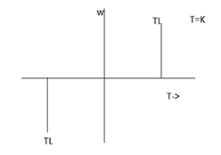
(a) Constant Torque type Load
The speed – torque characteristic of this type of load is given by T=K. Working motor have each mechanical nature of work like shaping, cutting, grinding or sharing, require constant torque irrespective of speed. Similarly cranes during the hoisting. Similarly cranes during the hoisting and conveyors handling constant weight of material / unit, time also exhibit this type of characteristics.
(b) Torque proportional to Speed
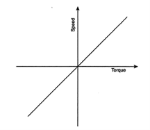
Separately executed DC generators connected to a constant resistance load, eddy current brakes & calendaring machines have a speed torque characteristics machines have a speed-torque characteristics given by T=Kw.
(c) Torque proportional to square of the Speed
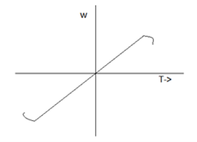
Example- Fans, Rotary pumps, compressors, ship propellers.
(d) Torque inversely proportional to speed
In such types of loads, torque is inversely proportional to speed or load power remains constant. Example- lathes, boring machines, steel mill coiler & electric traction load.
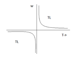
Q6) Explain in detail the Ward-Leonard method of speed control & armature voltage control?
A6) Ward Leonard Method of speed control is achieved by varying the applied voltage to the armature. This method was introduced in 1891. The connection diagram of the Ward Leonard method of speed control of a DC shunt motor is shown in the figure below.
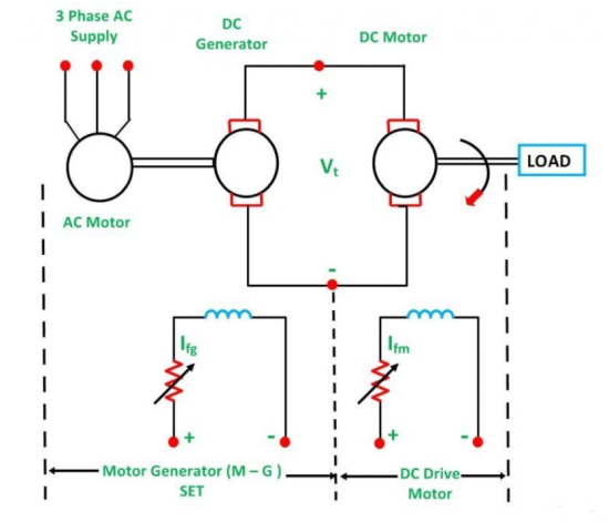
In the above system, M is the main DC motor whose speed is to be controlled, and G is a separately excited DC generator. The generator G is driven by a 3-phase driving motor which may be an induction motor or a synchronous motor.
The combination of an AC driving motor and the DC generator is called the Motor-Generator (M-G) set. The voltage of the generator is changed by changing the generator field current. This voltage when directly applied to the armature of the main DC motor, the speed of the motor M changes. The motor field current Ifm is kept constant so that the motor field flux ϕm also remains constant. While the speed of the motor is controlled, the motor armature current Ia is kept equal to its rated value.
The generated field current Ifg is varied such that the armature voltage Vt changes from zero to its rated value. The speed will change from zero to the base speed. Since the speed control is carried out with the rated current Ia and with the constant motor field flux, a constant torque is directly proportional to the armature current, and field flux up to rated speed is obtained. The product of torque and speed is known as power, and it is proportional to speed. Thus, with the increase in power, speed increases automatically.
The Torque and Power Characteristic is shown in the figure below:
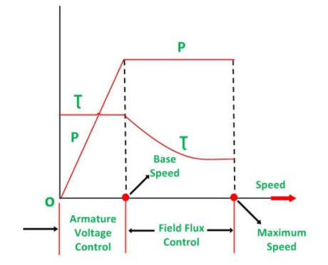
Hence, with the armature voltage control method, constant torque and variable power drive are obtained from speed below the base speed. The field flux control method is used when the speed is above the base speed. In this mode of operation, the armature current is maintained constant at its rated value, and the generator voltage Vt is kept constant.
The motor field current is decreased and as a result, the motor field flux also decreases. This means that the field is weakened to obtain higher speed. Since VtIa and EIa remain constant, the electromagnetic torque is directly proportional to the field flux ϕm and the armature current Ia. Thus, if the field flux of the motor is decreased the torque decreases. Therefore, the torque decreases, as the speed increases. Thus, in the field control mode, constant power and variable torque are obtained for speeds above the base speed. When the speed control over a wide range is required, a combination of armature voltage control and field flux control is used.
This combination permits the ratio of maximum to minimum speed available speeds to be 20 to 40. For closed-loop control, this range can be extended up to 200. The driving motor can be induction or synchronous motor. An induction motor operates at a lagging power factor. The synchronous motor may be operated at a leading power factor by over-excitation of its field. Leading reactive power is generated by an over-excited synchronous motor. It compensates for the lagging reactive power taken by other inductive loads. Thus, the power factor is improved.
A slip ring induction motor is used as p prime mover when the load is heavy and intermittent. A flywheel is mounted on the shaft of the motor. This scheme is known as Ward Leonard-Ilgener scheme. It prevents heavy fluctuations in supply current.
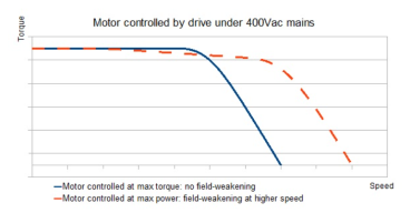
Q7) Discuss the flux/field weakening for High-Speed operation of DC Machine?
A7) Field weakening enables higher motor speeds by reducing the back EMF generated by the motor. Recall that back EMF (electromotive force) is voltage created when a coil turns inside a magnetic field, and it opposes the supply (driving) voltage. In order to “weaken” the field that creates back EMF, field weakening relies on a control method known as field-oriented control (FOC). Field oriented control (also referred to as vector control) is often used for AC induction motors that require dynamic torque and speed response and improved efficiency. With FOC, the quadrature (torque-producing, “q”) and direct (flux-producing, “d”) components of current are controlled independently, imitating the control scheme for a DC motor.
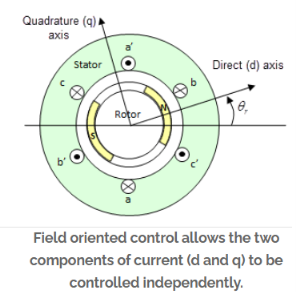
Here’s how field weakening is achieved: The d-axis of the stator current is referenced to, or in-line with, the axis of the rotor’s magnetic flux. So, adjusting the d-axis current (sometimes referred to as phase shifting) directly influences the rotor’s flux. In other words, positive d-axis current strengthens the rotor flux, whereas negative d-axis current weakens the rotor’s flux. More specifically, negative d-axis current weakens the field of the magnets — hence, the term field weakening.
Recall that in an AC motor, speed is determined by the frequency of the supply voltage. Because back EMF opposes (takes away from) the supply voltage, it is an important limiting factor in an AC motor’s achievable speed.
But back EMF is created by rotor flux. So, adding negative d-axis current reduces the rotor flux, which means that back EMF is also reduced. The result is that more of the drive’s bus voltage is used to create (increase) motor speed, rather than being used to overcome back EMF.
Q8) A 4 pole, lap wound DC motor has 540 conductors. Its speed found to be 1000 rpm. When it is made to run light. The flux per pole is 25 mWb. What will be the- (i) Induced EMF (ii) Armature current (iii) Stray losses iv) Lost torque?
A8) P = 4, A = P = 4
Running light means it is on no load.
... N0 = 1000 r.p.m.
Z = 540 & Flux = 25 x 10-3 Wb
... = ( PN0 Z)/(60A) = (25 x 10-3 x 4 x 1000 x 540)/ (60 x 4) = 225 V
i) Induced e.m.f., Eb0 = 225 V
Ii) From voltage equation, V = Eb + Ia Ra
... V = Eb0 + Ia0 Ra
... 230 = 225 + Ia0 x 0.8
... Ia0 = 6.25 A
Iii) On no load, power developed is fully the power required to overcome stray losses.
... Stray losses = Eb0 Ia0 = 225 x 6.25 = 1406.25 W
Iv) Lost torque = (Eb0 Ia0)/  a0 = 1406.25/ (2?N0 /60) = (1406.25 x 60)/(2×1000) = 13.428 N-m.
Q9) A 250-volt DC shunt motor has armature resistance of 0.25 ohm on load it takes an armature current of 50A and runs at 750rpm. If the flux of the motor is reduced by 10% without changing the load torque, find the new speed of the motor.
A9) Given data
V = 250
Ra = 0.25
Ia = 50
N1 = 750
Φ2 = 90%Φ1

Eb1 = V-Ia1Ra = 250-(50x0.25) = 237.5V
Eb2 = V-Ia2Ra
Load torque is constant
Ta1 = Ta2
Φ1Ia1 = Φ2Ia2
Ia2 = 55.55A
Eb2 = 250-55.55X0.25 = 236.12V
N2 = 828 rpm
Q10) A 4-pole, 250V series motor has wave connected armature with 1254 conductors. The flux per pole is 22 mWb when the motor is taking 50A. Armature resistance is 0.2 ohms and the field resistance is 0.2 ohms. Calculate the speed?
A10) Given, P=4, Z=1254, V=250V, Ra=Rse=0.2 ohms, Ia=50 A & flux= 22 mWb
 --- (i)


Substitute the given data in the above equation we will get the value of  as
as

Now calculate the speed using equation (i) also since armature is wave connected. A=2


Q11) A 250 V shunt motor takes a total current of 20 A. Resistance of the shunt field is 200 ohms and the armature is 0.3 ohms. Find the current in the armature and the back emf?
A11) Given, V=250V, I=20A, Rsh=200 ohms, Ra=0.3 ohms
To find Ia=? & Eb=?
Ia= I - Ish – (i)
Ish = (V/Rsh) – (ii)
From equation (ii), Ish = (250/200) = 1.25 A
From equation (i),
Ia = (20-1.25) = 18.75 A
Back EMF, Eb =?


Q12) A 4-pole, 220V lap connected DC shunt motor has 36 slots, each slot containing 16 conductors. It draws a current of 40 A from the supply. The field resistance and armature resistance are 110, 0.1 ohms respectively. The motor develops an output power 6kW. The flux per pole is 40 mWb. Calculate the speed?
A12) Given, P=4, Slots=36, A=P=4, Conductors/Slot=16, Z= 36*16=576, IL= 40A, Rsh= 110 ohms, Ra= 0.1 ohms, Poutput= 6 kW and flux= 40 mWb


Now,


Q13) A 4-pole generator with wave wound armature has 51 slots, each having 24 conductors. The flux per pole is 0.01 Wb. At what speed must the armature rotate to give an induced emf of 220V? What will be the voltage if the winding is lap & armature rotates at the same speed?
A13) P = 4, Slots = 51, Slots/conductor = 24, Total no. Of conductors Z= 51*24= 1224, Eb = 220 V and flux = 0.01 Wb
(i) N =?, When Eb = 220V for wave winding (A=2)


(ii) Eb = ?, When N= same as (i) and winding is lap (A=P)


Q14) An 8-pole lap-connected armature driven 400 rpm is required to generate 250V. The useful flux per pole is 0.05Wb. If the armature has 150 slots, calculate the suitable no. Of conductors per slot?
A14) Given, P = 8, N = 400 rpm, Eb = 250V, Flux per pole = 0.05 Wb, Slots = 150, A = P = 8, since it is lap connected


Therefore,
Conductors/Slot = 750/150 = 5
Q15) A 110V DC shunt generator delivers a load current of 50 A. The armature resistance is 0.2 ohms and the field resistance is 55 ohms. The generator is rotating at a speed of 1800 rpm, has 6 poles lap wound and has a total of 360 conductors. Calculate:
(i) The no load voltage in the armature, Eb
(ii) Flux per pole, 
A15) Given, V=110V, I = 50A, Ra = 0.2 ohms, Rf = Rsh = 55 ohms, N = 1800 rpm, P = 6, Z = 360, A= P = 6, since it is lap wound
 —(i)
—(i)
 -- (ii)
 -- (iii)
Therefore, from equation (iii)

From equation (ii)

From equation (i)


Q16) A 4-pole lap wound 750 rpm shunt generator has an armature resistance of 0.4 ohms & field resistance of 200 ohms. The armature has 720 conductors and the flux per pole is 3*10-3 Wb. If the load resistance is 10 ohms, determine the terminal voltage?
A16) Given, P = 4, N = 750 rpm, Ra = 0.4 ohms, Rf = Rsh = 200 ohms, Z = 720,  = 3*10-3 Wb, RL = 10 ohms and A = P = 4


Shunt & load resistance are in parallel = (10*200)/ (10+200) = 9.52 ohms
The above resistance is in series with armature resistance, Ra+9.52 = 0.4+9.52 = 9.92 ohms
Armature current, Ia = Eb/Total circuit resistance = (270/9.92) = 27.2 A
Armature drop = Ia * Ra = 27.2*0.4 = 10.88V
Terminal Voltage = EMF – Drop
Terminal Voltage = 270 – 10.88 = 259.12 V
Q17) A shunt generator supplies a load of 10 kW at 200 V through a pair of feeders of total resistance 0.05 ohms. Armature resistance is 0.1 ohms. Shunt field resistance is 100 ohms. Find the terminal voltage & generated emf of the generator?
A17) Given, PL = 10 kW, VL = 200V, RFeeder = 0.05 ohms, Ra = 0.1 ohms, Rf = Rsh = 100 ohms
 —(i)
—(i)
But,  -- (ii)
 -- (iii)
Terminal Voltage,  – (iv)
 -- (v)
Current,  – (vi)
Therefore, substituting in above equations,
From eq (vi), 
From eq (v), Drop in feeders = 2.5 V
From eq (iv), V = 202.5 V
From eq (iii), 
From eq (ii), 
From eq (i), 
Q18) A 4-pole, 100V shunt generator with lap connected armature, having field & armature resistance of 50 ohms & 0.1 ohms respectively, supplies sixty lamps of 100V, 40 W. Calculate the total armature current, the current per path & the generated emf. Allow a contact drop of 1 volt per brush.
A18) A = P = 4, V = 100 V, Rf = Rsh = 50 ohms, Ra = 0.1 ohms, Total load = 60*40 = 2400 W, VL=100 V, Contact drop/brush = 1 V
 -- (i)


Therefore, from eq(i), 
Current per path, 
 –(ii)
–(ii)
But brush drop = 2*1 = 2V
Substituting in the eq (ii)

Q19) A DC shunt motor supplied from a 400 V supply takes an armature current of 25 A & runs at 900 rpm. Calculate the speed at which it will run if supplied a 230 V supply taking armature current of 15 A. The resistance of armature is 0.8 ohms. Assume the flux per pole at 230 V is reduced to 75% of its value at 400 V.
A19) Case 1: V1 = 400 V, Ia1 = 25 A, flux per pole =  , N1 = 900 rpm
Case 2: V2 = 230V, Ia2 = 15 A, flux per pole =  , N2 =?


Q20) The armature current of a series motor is 60 A when on full load. If the load is adjusted such that the armature current decreases to 40 A. Find the new torque expressed as % of full load torque. The flux for a current 40 A is 70% of that when current is 60 A.
A20) Given, Case-1 Full Load: Ia1= 60 A, flux per pole =  , T1 = TFL
Case-2: Ia2 = 40 A, flux per pole = 0.70

 and
and 


New Torque is 46.6% of Full Load Torque