Unit - 2
Chopper fed DC drive
Q1) Explain the working of a DC Chopper & its Duty Cycle?
A1) A DC chopper is a circuit in which a thyristor is used to switch on supply to the load for a certain interval and the switch off the supply for another certain interval. This cycle of operations is repealed. The thyristor acts as a fast-acting switch. For turning on the thyristor, a gate signal is applied. To turn it off some method of forced commutation is needed.
Working Principle
A chopper is a high speed ON/OFF switch. It connected source to load and disconnects the load from the source at a fast speed. Figure below represents the simple circuit to show its working principle.
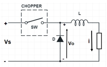
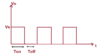
In this circuit, the switch SW is chopper. This switch can be made ON and OFF at a very high speed. In this way, the load may be connected and disconnected from the supply source Vs. When the switch is ON, the load voltage is equal to the source voltage Vs and when the switch is OFF, load voltage becomes equal to ZERO. Thus, a chopped voltage across the load is obtained. The output voltage i.e., voltage across the load is shown in figure below.
It should be noted here that, when the switch SW is made OFF, the load current finds its path through freewheeling diode D. Therefore, diode D acts as a short and hence the voltage across the load becomes zero. Inductor in the chopper is an essential thing. This inductor makes diode D forward biased when the switch SW is OFF.
It should also be noted that, even though the switch SW is made OFF, the load current doesn’t become ZERO. Rather, it flows through the freewheeling diode, inductor L and load. In fact, the load current is continuous as shown below.
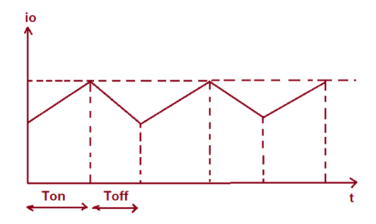
It may be seen from the above waveform of output current of chopper that, during ON time, the current rises whereas during OFF time, the load current io decays.
The time for which chopper connects the load from source is called ON time i.e., TON. Whereas, the time for which load is disconnects from source is called OFF time i.e., TOFF.
Duty Cycle
Duty cycle of chopper is defined as the ratio of ON time to the total time period. It is denoted by symbol α. Total time period is the sum of ON and OFF time.
Duty Cycle = TON / (TON+TOFF)
Assuming (TON+TOFF) = T, duty cycle is given as below.
Duty Cycle, α = (TON / T)
Q2) How speed is controlled in a chopper fed DC Control?
A2) D.C motor is considered a SISO (Single Input and Single Output) system having torque/speed characteristics compatible with most mechanical loads. This makes a DC motor controllable over a wide range of speeds by proper adjustment of the terminal voltage. A simple chopper – fed DC motor drive is shown in the below given figure. The basic principle behind DC motor speed control is that the output speed of DC motor can be varied by controlling armature voltage for speed below and up to rated speed keeping field voltage constant. The armature voltage can be controlled by controlling the duty cycle of the converter (here the converter used is a DC chopper).
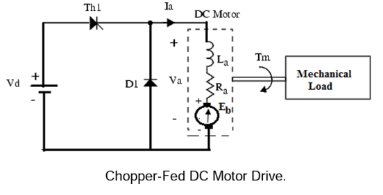
In the above figure, the converter output gives the dc output voltage Va required to drive the motor at the desired speed. In this diagram, the DC motor is represented by its equivalent circuit consisting of inductor La and resistor Ra in series with the back emf (Eb). The thyristor Th1 is triggered by a pulse width modulated (PWM) signal to control the average motor voltage. Theoretical waveforms illustrating the chopper operation are shown in the given below figures.
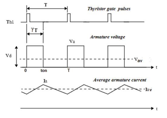
The average armature voltage is a direct function of the chopper duty cycle  ,
,

Note that this relation is valid only when the armature current is continuous. In steady state, the armature average current is equal to

Where Iav =average armature current (A)
Eb is the internal generated voltage (back emf) is given by;

Finally solving for the motor’s speed,
 or
or

Where n = speed in rpm & motor torque, 

At starting, n=0, the starting torque  may be found as,

Therefore,

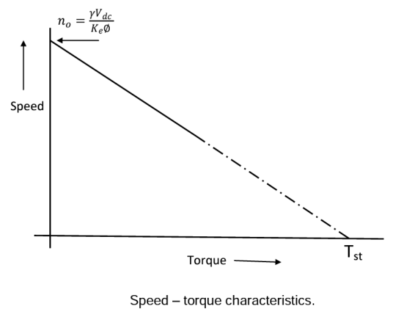
Q3) Explain the steady state operation of a chopper fed DC Drive?
A3) Consider a type-A chopper as shown in the figure below with RLE load. The waveforms for load current i0 & the load voltage v0. For continuous conduction & for discontinuous conduction can also be seen in the given figure. It can be clearly seen that the periodic time ‘T’ is higher for discontinuous conduction. The expression for load current helps to determine (i) the current profile over periodic time ‘T’ (ii) the current ripple & (iii) whether the current is discontinuous or continuous.
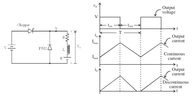
When the current exceeds Imax the chopper is turned off & when the current reduces to Imin, the chopper is turned on.
Mode-1: Expression for load current I0 when chopper is ON. The differential equation governing the performance of the chopper in this mode will be
Vs=R*i+L(di/dt) +E for 0≤t≤Ton ---(i)
Mode-2: When the chopper is off, the differential equation governing its performance becomes
0=R*i+L(di/dt) +E for Ton<t≤T --- (ii)
The solution of equations (i) & (ii) may be obtained by the use of Laplace Transform. Therefore, Imax & Imin is derived as-


- When the chopper is ON, supply voltage V is connected across the load.
- When the chopper is OFF, v0 =0 & load current continues to flow in the same direction through the free-wheeling diode.
- The average values of output voltage & current are always positive.
This kind of chopper also known as Class-A chopper is a step-down chopper in which power flows from source to load & it is used to control the speed of DC motor.
Q4) Explain the Armature current waveform with its Ripple factor?
A4) Theoretical waveforms illustrating the chopper operation are shown in the below figure. In this case the average armature voltage is a direct function of the chopper duty cycle γ, i.e., Vav = γ Vd. Two modes of operation may result when the chopper operates with DC motor load, namely, continuous armature current operation and discontinuous armature current operation modes as illustrated in the figure below. In both cases, the armature voltage and current waveforms are different in shape and each has its own analytical properties.
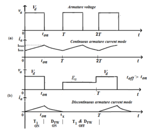
The armature voltage waveform  applied to the d.c. Motor for
Continuous current operating mode shown in figure (a) is given by
 ----- (i)
In order to analyze all equations in terms of (ωt) rather than the time (t) which gives more convenient and simple way for harmonic analysis, let the repetition periodicity, in the above figure, be designated as 2π radians, hence

The ON period of the chopper  is,
is, 
Therefore, EQ(i) can be re-written as

Hence, the average value Va of the armature voltage va( ) is
) is


The rms value of the armature voltage waveform is given by


The ripple factor, defining the ratio of the ac components to the average value is given by-


The ripple factor =0 for full conduction when 
Q5) What are the different type of losses in a DC Chopper i.e., Motor?
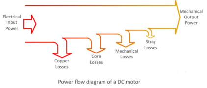
A5) In a dc motor, input power is in the form of electrical and output power is in the form of mechanical. In a practical machine, whole of the input power cannot be converted into output power as some power is lost in the conversion process. This causes the efficiency of the machine to be reduced. Efficiency is the ratio of output power to the input power. Thus, in order to design rotating dc machines (or any electrical machine) with higher efficiency, it is important to study the losses occurring in them.
There are three categories in loss calculation of DC Motor-
- Copper Losses- These losses occur in armature and field copper windings. Copper losses consist of Armature copper loss, Field copper loss and loss due to brush contact resistance.
(a) Armature Copper Losses- This loss contributes about 30 to 40% to full load losses. The armature copper loss is variable and depends upon the amount of loading of the machine.
 ,
,
Where Ia=Armature current & Ra=Armature resistance
(b) Field Copper Loss- In the case of a shunt wounded field, field copper loss is practically constant. It contributes about 20 to 30% to full load losses.
 ,
,
Where If=Field current & Rf=Field resistance
(c) Loss due to Brush Contact Resistance- Brush contact resistance also contributes to the copper losses. Generally, this loss is included into armature copper loss.
Q6) What are different types of Iron Losses?
A6) Iron Losses (Core Losses)
As the armature core is made of iron and it rotates in a magnetic field, a small current gets induced in the core itself too. Due to this current, eddy current loss and hysteresis loss occur in the armature iron core. Iron losses are also called as Core losses or magnetic losses.
(a) Hysteresis loss is due to the reversal of magnetization of the armature core. When the core passes under one pair of poles, it undergoes one complete cycle of magnetic reversal. The frequency of magnetic reversal is given by,
 (Where, P = no. Of poles and N = Speed in rpm)
The loss depends upon the volume and grade of the iron, frequency of magnetic reversals and value of flux density. Hysteresis loss is given by, Steinmetz formula:
 watts
watts
Where,  =Steinmetz Hysteresis Constant, V= volume of core in m3, f= frequency
(b) Eddy current loss: When the armature core rotates in the magnetic field, an emf is also induced in the core (just like it induces in armature conductors), according to the Faraday's law of electromagnetic induction. Though this induced emf is small, it causes a large current to flow in the body due to the low resistance of the core. This current is known as eddy current. The power loss due to this current is known as eddy current loss.
- Mechanical Losses- Mechanical losses consist of the losses due to friction in bearings and commutator. Air friction loss of rotating armature also contributes to these. These losses are about 10 to 20% of full load losses.
In addition to the losses stated above, there may be small losses present which are called as stray losses or miscellaneous losses. These losses are difficult to account. They are usually due to inaccuracies in the designing and modeling of the machine. Most of the times, stray losses are assumed to be 1% of the full load.
Q7) Give the details of efficiency of a DC Drive?
A7)
- Losses affect efficiency of a machine, its operating cost & causes a rise in temperature thereby affecting the machine insulation & performance & reduces the loading capability. Therefore, the efficiency of a machine must be evaluated to understands its performance.
- These losses can be magnetic losses (also known as iron loss/core loss denoted by Wc), copper losses (also known as armature loss & denoted by I2a*Ra) or mechanical losses (due to air friction).
- Conditions for maximum efficiency-

Output= V*I
Input= Output + Losses = VI+Wc+ I2a*Ra


For efficiency to be maximum, the denominator needs to be minimum. Therefore, on differentiating the denominator we get,
 and
and 
Q8) A DC shunt motor takes a current of 80A on a 480V supply and runs at 960 rpm/ The armature resistance is 0.25 Ω & field resistance is 120 Ω. A chopper is used to control the speed of the motor in the range of 400-750 rpm having constant torque. The on-period of the chopper is 3 ms. The field is supplied directly from 480 V. Determine the range of frequencies of the chopper?
A8) Field current of the motor If = 480/120 = 4A
Therefore, Armature Current = 80-4 = 76 A
Now, Back emf at 960 rpm = 480-(76*0.25) = 461 V
Back emf at 400 rpm = (400/960) *461 = 191.88 V
Terminal Voltage required = 191.88+(76*0.25) = 210.88 V
Therefore, Chopping period, T = (Supply/Terminal) Voltage*Time = (480/210.88) *0.0003
Hence, Chopping Frequency = (210.88*103)/ (480*3) = 146.44 HZ
Now, back emf at 750 rpm = (750/960) *461 = 360.16 V
Therefore, terminal voltage required = 360.16 + (76*0.25) = 379.16 V
Therefore, Chopper period = (480*3*10-3)/379.16
Chopper Frequency = (379.16*103)/ (480/3) = 263.31 Hz
Hence, the range of frequencies of chopper is 146.44 Hz < f <263.31 Hz
Q9) A DC series motor is fed from 600 V DC source through a chopper. The DC motor has following parameters-
Ra = 0.04 Ω, Rs = 0.06 Ω, k= 4*10-3 Nm/amp2
The average armature current of 300 A is ripple free. For a chopper duty cycle of 60%, determine (i) Input power from source, (ii) Motor Speed & (iii) Motor Torque.
A9) (i) Power input to motor


(i) For a DC series motor,


(ii) Motor Torque, 
Q10) A DC shunt generator has a full load output of 30kW at a terminal voltage of 250V. The mechanical & iron losses are 1300W. The armature & shunt field resistance are 0.13 Ω & 125 Ω respectively. Calculate the efficiency of generator at full load & maximum efficiency of the generator.
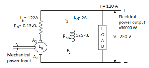
A10) Given data, Pout= 30kW/30000W, V = 250V, Mechanical & iron loss = 1300 W, Ra = 0.13 Ω, Rsh = 125 Ω,
IL = Pout/V = 30000/250 = 120A
Ish = V/Rsh = 250/125 = 2A
Ia = IL + Ish = 120+2 = 122A
Armature copper loss = Ia2Ra = 122*122*0.13 = 1934.92W
Field Copper loss = I2sh*Rsh = 2*2*125 = 500W
Total constant loss at full load = 1300+500 = 1800 W
Total loss = variable loss (armature copper loss) + constant loss = 1934.92+1800 = 3734.92W


Total constant loss at full load = 1300 + 500 = 1800 W
At maximum efficiency, variable loss = constant loss
Therefore, Ia2Ra = 1800, Ia = (1800/0.13)1/2 = 117.669 A
IL = Ia - Ish = 117.669 – 2 = 115.669 A
Output at this load = V*IL = 250*115.669 = 28917.25 W


Q11) A 20kW, 440V, short shunt compound generator has a full efficiency of 87%. If the resistance of armature & interpoles is 0.4 Ω and that of series shunt field is 0.25 Ω & 240 Ω respectively. Calculate the combined bearing friction, windage & core loss of the machine?
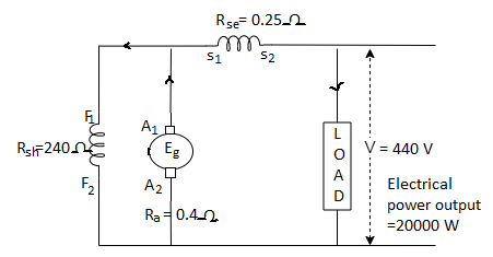
A11) Given data, Pout = 20kW=20000W, V = 440V,  , Ra = 0.4 Ω, Rse = 0.25 Ω, Rsh = 240 Ω


Total Loss = Input Power – Output Power = 22988.5-20000 = 2988.5 W

Voltage across series field winding = Ise * Rse = 45.45*0.25 = 11.36 V
Therefore, Voltage across shunt field winding = V’ = 440+11.36 = 451.36 V


Total Loss = 2988.5 W
Armature Copper Loss = 
Shunt Field Winding Loss = 
Series Field Winding Loss = 
Total Copper Loss = 896.07+848.256+516.42 = 2260.75 W
Q12) A 200V DC shunt motor takes a current of 7A when running unloaded. Its armature & shunt field resistance are 0.2 Ω & 100 Ω respectively. Calculate (i) Iron & Friction Losses (ii) Shaft power when the load current is 52A assuming iron & friction losses are constant.
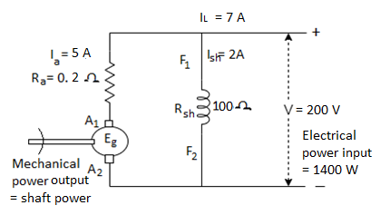
A12) Given data, V = 200V, INL = 7A, Ra = 0.2 Ω, Rsh = 100 Ω
Power Input at no load = 200*7 = 1400 W
Input Power = Output Power + Losses
At no load, Output Power = 0, hence Input Power = Losses
Now, 

Armature Copper Loss at no load = 
Shunt Field Winding Copper Loss = 
Total No Load loss = Iron & Friction Losses + Copper Losses
Iron & Friction Losses = 1400 – (400+5) = 995W
When IL = 52 A

Therefore, Armature Copper Loss = 
Total Copper Loss = Armature Copper Loss + Field Copper Loss = 500+400= 900W
Total Losses = Iron & Friction Losses + Copper Loss = 995+900 = 1895W
Shaft Power = Input Power – Losses = (200*52)-1895 = 8505W
Q13) A DC Series motor on full load takes 50A from 230V DC mains. The total resistance of the motor is 0.22 Ω. If the iron & friction losses together amount 5% of the input, calculate the power delivered by the motor shaft & its efficiency. Total voltage drop due to brush contact is 2V.
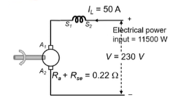
A13) Given data, IFL = 50A, V = 230V, (Ra+Rse = 0.22 Ω, Iron & Friction losses = 5% if Input Power
Power Input at full load = 230*50 = 11500W
Iron & Friction Loss = 0.05*11500 = 575W
Armature & Series Field Winding Copper Loss = 
Brush contact loss = Vbrush*Ia = 2*50 = 100W
Total Losses = Iron & Friction Losses + Copper Losses + Brush Contact Loss
Therefore, Total Losses = 575+550+100 = 1225W
Shaft Power = Input Power – Losses = 11500-1225 = 10275W

Q14) The chopper used for on-off control of a DC separately-excited motor has supply voltage of 230V DC, an on-time of 10 m sec and off-time 15 m sec. Neglecting armature inductance and assuming continuous conduction of motor current, calculate the average load current when the motor speed is 1500 rpm and has a voltage constant of Kb = 0.5V/rad per sec. The armature resistance is 3 Ω.
A14) Chopper duty cycle is

For the motor armature circuit,


Q15) A DC chopper is used to control the speed of a separately-excited DC motor. The DC supply voltage is 220V, armature resistance ra = 0.2 Ω and motor constant Ka = 0.08 V/rpm. This motor drives a constant torque load requiring an average armature current of 25A. Determine (a) the range of speed control (b) the range of duty cycle. Assume the motor current to be continuous.
A15) For the motor armature circuit,

As motor drives a constant torque load, motor torque Te is constant and therefore armature current remains constant at 25A.
Minimum possible motor speed is N = 0


Maximum possible motor speed corresponds to  i.e., when 220V DC is directly applied & no chopping is done.


Therefore, Range of speed control 0<N<2687.5 and corresponding range of duty cycle is 1/44< <1.
<1.
Q16) A step-up chopper is used to deliver load voltage of 400 V from a 220V DC source. If the blocking period of thyristor is 60 µs. Determine the required pulse width.
A16) Given data, V0 = 400 V, Vs = 220 V, 


Q17) A step-up chopper has a supply voltage of 250V while the output voltage is 400V. If the total time period of the chopper is 100 µsec. Determine the (i) pulse width of output voltage (ii) if the pulse width is reduced to 1/3 for the constant frequency operation, find the output voltage?
A17) (i) 


(ii) 


Q18) In a step-down chopper, the input voltage being 230V DC. The load voltage is 150V. If the chopping frequency is 4 KHz. Find the on & off period of the thyristor in each cycle?
A18) Given,  ,
,  ,
,  ,
, 


Q19) Input to the step-up chopper is 200V. The output required is 600V. If the conducting time of thyristor is 200 µsec. Compute chopping frequency, if the pulse width is halved for constant frequency of operation, find the new output voltage?
A19) Given data, V = 200V,  ,
, 


Chopping Frequency, f = 1/T
f = 3.33 KHz
Pulse width is halved, 
As frequency is constant, f = 3.33 KHz, T = 1/f hence T = 300µs
Therefore, Output Voltage will be


