Back to Study material
PS2

Unit - 5

Fault Analysis and Protection Systems

Q1) How do we detect & locate faults in transmission lines, power cables and wiring systems?

A1)

  • In transmission lines, the fault is very easy to identify as the crisis is generally noticeable. For instance, once any tree has fallen over the transmission line, otherwise, an electrical pole can be damaged as well as the conductors are lying on the earth.
  • In a power cable, an insulation fault cannot occur at low voltages. So, a thumper test is used by applying a high voltage pulse, high energy to the cable. The fault location can be done by listening to the discharge sound at the error. When this test donates to harm at the site of cable, it is useful as the faulted location would have to be re- insulate once set up in any case.
  • In wiring systems, the location of the fault can be found throughout the verification of the wires. In difficult wiring systems, wherever the wires may be buried, these faults are placed through a Time-domain reflectometer that sends a pulse down the wire & after that examines the reflected signal to recognize faults in the electrical wire.
  •  

    Q2) What are short circuit faults? How are they caused?

    A2)

  • Short circuit faults mainly occur because of failure within insulation among phase conductors and earth. An insulation failure can cause a short-circuit path formation that activates short-circuit conditions within the circuit.
  • The definition of a short circuit is, an abnormal connection of extremely less impedance among two points of dissimilar potential, whether completed by chance or purposely. These faults are the most common types which result in the abnormal high current flow throughout the transmission lines or equipment.
  • The short circuit faults may occur because of the following reasons:
  • a)     These faults may occur because of the internal otherwise external effects

    b)    Internal effects are transmission lines breakdown, equipment damage, insulation aging, corrosion of insulation within the generator, improper installations of electrical devices, transformers, and their inadequate design.

    c)     These faults can be occurred because of outside effects of apparatus, insulation failure because of lighting surges & mechanical damage by the public.


    Q3) What are open circuit faults? What are their effects?

    A3)

  • The open-circuit faults mainly occur because of the malfunction of one otherwise more conductor used in the power system. These faults mainly occur because of common issues like failure of joints in overhead lines, cables, failure in the phase of a circuit breaker, melting of conductor or fuse within one phase or more phases.
  • These faults are also known as series faults which are unbalanced types otherwise unsymmetrical types apart from 3-phase open fault.
  • These faults are categorized into three types like following:
  • a)     Open Conductor Fault

    b)    Two conductors Open Fault

    c)     Three Conductors Open Fault

  • These faults can be caused because of the circuit malfunctioning as well as broken conductor in 1-phase or more phases. The effects of open circuit faults include the following:
  • a)     Electrical power system irregular operation

    b)    These faults may danger to animals as well as human beings

    c)     In particular, a portion of the network, when the voltage is exceeded beyond normal values then it causes insulation failures and develops short circuit faults.

    d)    Even though, these types of circuit faults can be accepted for a long time as compared with short circuit type faults, because these faults must be detached to decrease the high damage.


    Q4) Which faults can occur in transmission lines?

    A4)

  • Normally, a power system operates under balanced conditions. When the system becomes unbalanced due to the failures of insulation at any point or due to the contact of live wires, a short–circuit or fault is said to occur in the line. Faults may occur in the power system due to the number of reasons like natural disturbances (lightning, high-speed winds, earthquakes), insulation breakdown, falling of a tree, bird shorting, etc.
  • Faults that occur in transmission lines are broadly classified as:
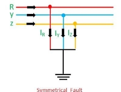
  • a)     Symmetrical faults: In such types of faults, all the phases are short-circuited to each other and often to earth. Such fault is balanced in the sense that the systems remain symmetrical, or we can say the lines displaced by an equal angle (i.e., 120° in three phase line). It is the most severe type of fault involving largest current, but it occurs rarely. For this reason, balanced short- circuit calculation is performed to determine these large currents.

    symmetrical-fault

    b)    Unsymmetrical faults: Unsymmetrical faults involve only one or two phases. In unsymmetrical faults the three phase lines become unbalanced. Such types of faults occur between line-to-ground or between lines. An unsymmetrical series fault is between phases or between phase-to-ground, whereas unsymmetrical shunt fault is an unbalanced in the line impedances.

  • Effect of faults on transmission line: Faults can damage or disrupt power systems in several ways. Faults increase the voltages and currents at certain points on the system. A large voltage and current may damage the insulation and reduces the life of the equipment. Faults can cause the system to become unstable, and the three-phase system equipment operates improperly. Hence, it is necessary that, on the occurrence of the fault, the fault section should be disconnected. So, the normal operation of the rest of the system is not affected.
  •  


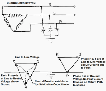
    Q5) State the advantages & disadvantages of ungrounded neutral system.

    A5)

  • Advantages
  • After the first ground fault, assuming it remains as a single fault, the circuit may continue in operation, permitting continued production until a convenient shut down for maintenance can be scheduled.

  • Disadvantages
  • a)     The interaction between the faulted system and its distributed capacitance may cause transient over-voltages (several times normal) to appear from line to ground during normal switching of a circuit having a line-to ground fault (short). These over voltages may cause insulation failures at points other than the original fault.

    b)    A second fault on another phase may occur before the first fault can be cleared. This can result in very high line-to-line fault currents, equipment damage and disruption of both circuits.

    c)     The cost of equipment damage.

    d)    Complicate for locating fault(s), involving a tedious process of trial and error: first isolating the correct feeder, then the branch, and finally, the equipment at fault. The result is unnecessarily lengthy and expensive down downtime.


    Q6) State the advantages & disadvantages of grounded neutral system.

    A6)

  • Advantages
  • The main advantage of solidly earthed systems is low over voltages, which makes the earthing design common at high voltage levels (HV).

  • Disadvantages
  • a)     This system involves all the drawbacks and hazards of high earth fault current: maximum damage and disturbances.

    b)    There is no service continuity on the faulty feeder.

    c)     The danger for personnel is high during the fault since the touch voltages created are high.

  • Applications
  • a)     Distributed neutral conductor

    b)    3-phase + neutral distribution

    c)     Use of the neutral conductor as a protective conductor with systematic earthing at each transmission pole

    d)    Used when the short-circuit power of the source is low


    Q7) What do you understand by symmetrical faults?

    A7) Symmetrical or Balanced Faults

  • When these faults occur, the system remains in symmetrical state, but these faults cause very severe damage to electrical power system.
  • They occur infrequently in the power systems.
  • Only 2-5% of system faults are balanced faults.
  • Analysis of balanced faults is easy and is carried out on a phased basis.
  • 3-phase fault analysis is needed to select set-phase relays, rating of protective switchgear and rupturing capacity of the circuit breakers.
  • The balanced faults are classified into two types:
  • a)     Line – Line – Line Fault (L – L – L Fault): The system remains balanced even after the fault occurs. This type of fault occurs rarely, but when it does occur, it is a harsh kind of fault which holds the largest current, which is used to determine the rating of the Circuit Breaker.

    b)    Line – Line – Ground Fault (L – L – L – G Fault): This fault comprises of all the 3- phases of the system, and occurs among the ground terminal in addition to the 3-phases of the system. The probability of occurrence of this type of fault is 2-3%.


    Q8) What do you understand by unsymmetrical faults?

    A8) Unsymmetrical or Unbalanced Faults

  • These are very common and less severe in nature.
  • These are also called unbalanced or unsymmetrical faults because their occurrence causes unbalance in the system.
  • Unbalance of the system means that the impedance values are different in each phase causing unbalanced current to flow in the phases.
  • These are relatively difficult to analyze and are carried by per phase basis.
  • These faults are mainly of 3 types:
  • a)     Line to Ground Faults (L-G): It is the most common fault and 75-80% of faults are of this type, causing the conductor to make contact with the ground.

    b)    Line to Line Faults (L-L): This occurs when two conductors make contact with each other mainly due to swinging of lines during heavy winds. Only 5- 10% of the faults are of this type.

    c)     Double Line to Ground Faults (LL-G): Both the two lines touch each other through the ground. There is 10% probability of occurrence of such faults.


    Q9) What do you understand by Resistance earthed systems?

    A9)

  • Resistance grounding has been used in three-phase industrial applications for many years and it resolves many of the problems associated with solidly grounded and ungrounded systems.
  • Resistance Grounding Systems limits the phase-to-ground fault currents. The reasons for limiting the Phase to ground Fault current by resistance grounding are:
  • a)     To reduce burning and melting effects in faulted electrical equipment like switchgear, transformers, cables, and rotating machines.

    b)    To reduce mechanical stresses in circuits/Equipments carrying fault currents.

    c)     To reduce electrical-shock hazards to personnel caused by stray ground fault.

    d)    To reduce the arc blast or flash hazard.

    e)     To reduce the momentary line-voltage dip.

    f)       To secure control of the transient over-voltages while at the same time.

    g)    To improve the detection of the earth fault in a power system.

  • Grounding Resistors are generally connected between ground and neutral of transformers, generators and grounding transformers to limit maximum fault current as per Ohms Law to a value which will not damage the equipment in the power system and allow sufficient flow of fault current to detect and operate Earth protective relays to clear the fault. Although it is possible to limit fault currents with high resistance Neutral grounding Resistors, earth short circuit currents can be extremely reduced. As a result of this fact, protection devices may not sense the fault.
  • Therefore, it is the most common application to limit single phase fault currents with low resistance Neutral Grounding Resistors to approximately rated current of transformer and / or generator.
  • In addition, limiting fault currents to predetermined maximum values permits the designer to selectively coordinate the operation of protective devices, which minimizes system disruption and allows for quick location of the fault.
  • There are two categories of resistance grounding:
  • Low resistance Grounding
  • High resistance Grounding
  •  


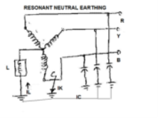
    Q10) What do you understand by Resonant earthed systems?

    A10)

  • Adding inductive reactance from the system neutral point to ground is an easy method of limiting the available ground fault from something near the maximum 3 phase short circuit capacity (thousands of amperes) to a relatively low value (200 to 800 amperes).
  • To limit the reactive part of the earth fault current in a power system a neutral point reactor can be connected between the transformer neutral and the station earthing system.
  • A system in which at least one of the neutrals is connected to earth through an
  • Inductive reactance
  • Petersen coil / Arc Suppression Coil / Earth Fault Neutralizer
  • The current generated by the reactance during an earth fault approximately compensates the capacitive component of the single-phase earth fault current, is called a resonant earthed system.
  • The system is hardly ever exactly tuned, i.e., the reactive current does not exactly equal the capacitive earth fault current of the system.
  • A system in which the inductive current is slightly larger than the capacitive earth fault current is over compensated. A system in which the induced earth fault current is slightly smaller than the capacitive earth fault current is under compensated.
  • https://electricalnotes.files.wordpress.com/2012/01/6.png?w=178&h=133

  • However, experience indicated that this inductive reactance to ground resonates with the system shunt capacitance to ground under arcing ground fault conditions and creates very high transient over voltages on the system.
  • To control the transient over voltages, the design must permit at least 60% of the 3-phase short circuit current to flow underground fault conditions.
  • Example: A 6000-amp grounding reactor for a system having 10,000 amps 3 phase short circuit capacity available. Due to the high magnitude of ground fault current required to control transient over voltages, inductance grounding is rarely used within industry.
  •  


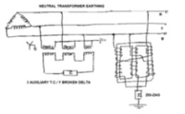
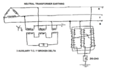
    Q11) What are Earthing Transformers?

    A11)

  • For cases where there is no neutral point available for Neutral Earthing (e.g., for a delta winding), an earthing transformer may be used to provide a return path for single phase fault currents.
  • https://electricalnotes.files.wordpress.com/2012/01/7.png?w=224&h=138

  • In such cases the impedance of the earthing transformer may be sufficient to act as effective earthing impedance. Additional impedance can be added in series if required. A special ‘zig-zag’ transformer is sometimes used for earthing delta windings to provide a low zero-sequence impedance and high positive and negative sequence impedance to fault currents.
  •  

    Q12) What do you understand by sequence networks of power system?

    A12)

  • Sequence networks of power systems are very useful for computing unsymmetrical faults at different points of a power system network. The knowledge of positive- sequence network is necessary for load-studies on power systems. If the stability studies involve unsymmetrical faults, then negative- and zero-sequence networks are also required.
  • A power system network consists of synchronous machines, transformers and lines. Using these, complete sequence networks of a power system can be easily drawn. The positive-sequence network is drawn by examining one line diagram of the power system. In fact, the single line reactance diagram, as employed for calculation of symmetrical fault current, is the positive-sequence diagram of the power system.
  • The negative-sequence network is quite similar to positive-sequence network—only generators or rotating machines may have different sequence impedances and the negative-sequence network does not contain any voltage source. The negative-sequence impedances for transmission lines and transformers are the same as the positive-sequence impedances.
  • In many cases only one sequence network is drawn for positive- and negative-sequence representation. The reference bus for positive- and negative-sequence networks is the system neutral. Any impedance connected between a neutral and ground is not included in the positive- and negative-sequence networks as neither of these sequence currents can flow through such an impedance.
  • Zero-sequence sub-networks for different elements of a power system can be easily combined to form complete zero-sequence network. The zero-sequence network does not contain any voltage source. Any impedance included in generator or transformer neutral becomes three times its value in a zero-sequence network. Special care needs to be taken in connecting the zero-sequence impedance of transformer.
  •  

    Q13) What are solidly neutral grounded systems?

    A13)

  • Solidly grounded systems are used for low voltage applications of 600 volts or less. In this system, the neutral point is connected to the earth.
  • This system reduces the problem of transient over voltages found in ungrounded system and provides path for the ground fault current.
  • However, if the reactance of the generator is too high, the issue of transient over voltages will not be resolved.
  • To maintain the safety of such systems, transformer neutral is grounded and grounding conductor must be extended from the source to the furthest point of the system within the same conduit.
  • This is done to maintain very low impedance to ground faults so that a relatively high fault current will flow, thereby ensuring that circuit breakers or fuses will resolve the fault quickly and hence, minimize damage.
  •  

    Q14) What are ungrounded neutral systems?

    A14)

  • It has no internal connection between the conductors and earth. However, a capacitive coupling exists between the ground surface and the system conductors.
  • This distributed capacitance causes no problems under normal operating conditions. On the contrary, it is beneficial as it establishes a neutral point for the system; Due to this, the phase conductors are stressed at line-to-neutral voltage above ground only.
  • Problems can, however, rise in ground fault conditions, causing failures in old motors and transformers, due to insulation breakdown.
  • Ungrounded neutral system

    Q15) Explain the term ‘Power System Protection’.

    A15)

  • Power system protection is a branch of electrical power engineering that deals with the protection of electrical power systems from faults through the disconnection of faulted parts from the rest of the electrical network. The objective of a protection scheme is to keep the power system stable by isolating only the components that are under fault, whilst leaving as much of the network as possible still in operation. Thus, protection schemes must apply a very pragmatic and pessimistic approach to clearing system faults. The devices that are used to protect the power systems from faults are called protection devices.
  • Protection systems usually comprise five components:
  • a)     Current and voltage transformers to step down the high voltages and currents of the electrical power system to convenient levels for the relays to deal with

    b)    Protective relays to sense the fault and initiate a trip, or disconnection, order

    c)     Circuit breakers to open/close the system based on relay and auto recloser commands

    d)    Batteries to provide power in case of power disconnection in the system

    e)     Communication channels to allow analysis of current and voltage at remote terminals of a line and to allow remote tripping of equipment.


    Q16) What are the functional requirements of a protection system or protective relay?

    A16)

  • Reliability: The most important requisite of protective relay is reliability. They remain inoperative for a long time before a fault occurs; but if a fault occurs, the relays must respond instantly and correctly.
  • Selectivity: The relay must be operated in only those conditions for which relays are commissioned in the electrical power system. There may be some typical condition during fault for which some relays should not be operated or operated after some definite time delay hence protection relay must be sufficiently capable to select appropriate condition for which it would be operated.
  • Sensitivity: The relaying equipment must be sufficiently sensitive so that it can be operated reliably when level of fault condition just crosses the predefined limit.
  • Speed: The protective relays must operate at the required speed. There must be a correct coordination provided in various power system protection relays in such a way that for fault at one portion of the system should not disturb other healthy portion. Fault current may flow through a part of healthy portion since they are electrically connected but relays associated with that healthy portion should not be operated faster than the relays of faulty portion otherwise undesired interruption of healthy system may occur. Again, if relay associated with faulty portion is not operated in proper time due to any defect in it or other reason, then only the next relay associated with the healthy portion of the system must be operated to isolate the fault. Hence it should neither be too slow which may result in damage to the equipment nor should it be too fast which may result in undesired operation.
  •  

    Q17) Define the Sequence Network for a Transformer?

    A17) Nowadays three-phase transformers are installed since they entail lower initial cost, have smaller space require­ments and higher efficiency. The positive sequence series impedance of a transformer equals its leakage impedance. Since a transformer is a static device, the leakage impedance does not change with alteration of phase sequence of balanced applied voltages. The negative Sequence Impedance and Networks of Transformers is also therefore equal to its leakage reactance. Thus, for a transformer

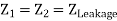
    Assuming such transformer connections that zero sequence currents can flow on both sides, a transformer offers a zero-sequence impedance which may differ slightly from the corresponding positive and negative sequence values. It is, however, normal practice to assume that the series impedances of all sequences are equal regardless of the type of transformer.

    The zero-sequence magnetizing current is somewhat higher in a core type than in a shell type transformer. This difference does not matter as the magnetizing current of a transformer is always neglected in short circuit analysis.

    Zero Sequence Networks of Transformers:

    Before considering the zero sequence networks of various types of transformer connections, three important observations are made:

  • When magnetizing current is neglected, transformer primary would carry current only if there is current flow on the secondary side.
  • Zero sequence currents can flow in the legs of a star connection only if the star point is grounded which provides the necessary return path for zero sequence currents. 
  •  


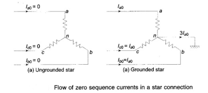
    No zero sequence currents can flow in the lines connected to a delta connection as no return path is available for these currents. Zero sequence currents can, however, flow in the legs of a delta—such currents are caused by the presence of zero sequence voltages in the delta connection.

    Q18) Define Sequence Impedance for Transmission Lines?

    A18) A fully transposed three-phase line is completely symmetrical and, therefore, the positive-and negative-sequence impedances of a transmission line are independent of phase sequence and are equal. The expression for inductive reactance, of “Elements of Power Systems” is valid for both positive and negative sequences. When only zero-sequence currents flow in a transmission line, the currents in each phase are identical in both magnitude and phase.

    Such currents return partly through ground and the rest through overhead ground wires. The magnetic field due to flow of zero-sequence currents through the transmission lines, ground wires and ground is very different from the magnetic field set up by the flow of positive- or negative-sequence currents. The zero-sequence impedance (particularly the reactance) is about 2 to 4 times the positive sequence impedance.


    Q19) Briefly explain Sequence Impedance for Synchronous Machine? 

    A19) An unloaded synchronous machine (generator or motor) grounded through a reactor of impedance Zn is shown in the figure. Ea, Eb and Ec are the induced emfs in the three phases. When an unsymmetrical fault occurs on the machine terminals, unbalanced currents la, Ib and Ic flow in the lines.

    If the fault involves ground, current In flows to neutral to ground via reactance Zn. Depending on the type of fault one or more of line currents may be zero. Unbalanced line currents can be resolved into their symmetrical components.

    There are three types of Impedance Network in a synchronous machine, they are as follows-

    (a)  Positive Sequence Impedance & Network

    (b) Negative Sequence Impedance & Network

    (c)  Zero Sequence Impedance & Network


    Q20) Briefly explain the computation in fault currents?

    A20) The knowledge of electrical fault condition is required to deploy proper different protective relays in different locations of electrical power system.

    Information regarding values of maximum and minimum fault currents, voltages under those faults in magnitude and phase relation with respect to the currents at different parts of power system, to be gathered for proper application of protection relay system in those different parts of the electrical power system. Collecting the information from different parameters of the system is generally known as electrical fault calculation.


    Fault calculation broadly means calculation of fault current in any electrical power system. There are mainly three steps for calculating faults in a system.

  • Choice of impedance rotations.
  • Reduction of complicated electrical power system network to single equivalent impedance.
  • Electrical fault currents and voltages calculation by using symmetrical component theory.
  •  

    If we look at any electrical power system, we will find, these are several voltage levels. For example, suppose a typical power system where electrical power is generated at 6.6 kV then that 132 kV power is transmitted to terminal substation where it is stepped down to 33 kV and 11 kV levels and this 11 kV level may further step down to 0.4 kv.

    Hence from this example it is clear that a same power system network may have different voltage levels. So, calculation of fault at any location of the said system becomes much difficult and complicated it try to calculate impedance of different parts of the system according to their voltage level.

    This difficulty can be avoided if we calculate impedance of different part of the system in reference to a single base value. This technique is called impedance notation of power system. In other words, before electrical fault calculation, the system parameters, must be referred to base quantities and represented as uniform system of impedance in either ohmic, percentage, or per unit values.

    Electrical power and voltage are generally taken as base quantities. In three phase system, three phase power in MVA or KVA is taken as base power and line to line voltage in KV is taken as base voltage. The base impedance of the system can be calculated from these base power and base voltage, as follows,

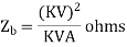
    Per unit is an impedance value of any system is nothing but the radio of actual impedance of the system to the base impedance value.

    Percentage impedance value can be calculated by multiplying 100 with per unit value.