Unit-2
Baseband Transmission
Q1) Explain Unipolar signalling in line coding?
A1) Unipolar signalling is also called as On-Off Keying or simply OOK.
The presence of pulse represents a 1 and the absence of pulse represents a 0.
There are two variations in Unipolar signalling −
Unipolar Non-Return to Zero NRZ
In this type of unipolar signalling, a High in data is represented by a positive pulse called as Mark, which has a duration T0 equal to the symbol bit duration. A Low in data input has no pulse.
The following figure clearly depicts this.

Fig 1 Uni-polar NRZ
Advantages
The advantages of Unipolar NRZ are −
Disadvantages
The disadvantages of Unipolar NRZ are −
Unipolar Return to Zero RZ
In this type of unipolar signaling, a High in data, though represented by a Mark pulse, its duration T0 is less than the symbol bit duration. Half of the bit duration remains high but it immediately returns to zero and shows the absence of pulse during the remaining half of the bit duration.
It is clearly understood with the help of the following figure.
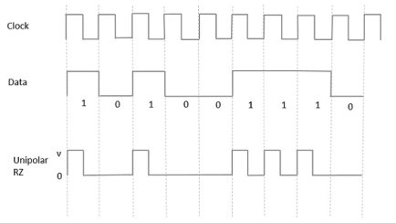
Fig 2 Unipolar RZ
Advantages
The advantages of Unipolar RZ are −
Disadvantages
The disadvantages of Unipolar RZ are −
Q2) Explain polar signalling form of line coding?
A2) There are two methods of Polar Signaling. They are −
Polar NRZ
In this type of Polar signaling, a High in data is represented by a positive pulse, while a Low in data is represented by a negative pulse. The following figure depicts this well.
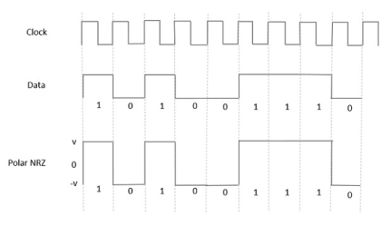
Fig 3 Polar NRZ
Advantages
The advantages of Polar NRZ are −
Disadvantages
The disadvantages of Polar NRZ are −
Polar RZ
In this type of Polar signaling, a High in data, though represented by a Mark pulse, its duration T0 is less than the symbol bit duration. Half of the bit duration remains high but it immediately returns to zero and shows the absence of pulse during the remaining half of the bit duration.
However, for a Low input, a negative pulse represents the data, and the zero level remains same for the other half of the bit duration. The following figure depicts this clearly.
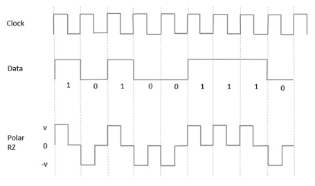
Fig 4 Polar RZ
Advantages
The advantages of Polar RZ are −
Disadvantages
The disadvantages of Polar RZ are −
Q3) Explain the bipolar signalling form of line coding?
A3) This is an encoding technique which has three voltage levels namely +, - and 0. Such a signal is called as duo-binary signal.
An example of this type is Alternate Mark Inversion AMIAMI. For a 1, the voltage level gets a transition from + to – or from – to +, having alternate 1s to be of equal polarity. A 0 will have a zero voltage level.
Even in this method, we have two types.
From the models so far discussed, we have learnt the difference between NRZ and RZ. It just goes in the same way here too. The following figure clearly depicts this.
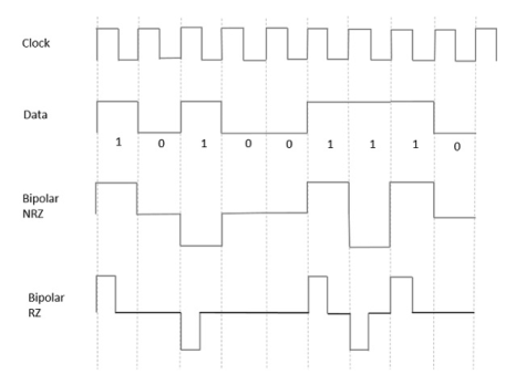
Fig 5 Bipolar RZ and Bipolar NRZ
The above figure has both the Bipolar NRZ and RZ waveforms. The pulse duration and symbol bit duration are equal in NRZ type, while the pulse duration is half of the symbol bit duration in RZ type.
Advantages
Following are the advantages −
Disadvantages
Following are the disadvantages −
Q4) Explain the modulation of M-ary QAM?
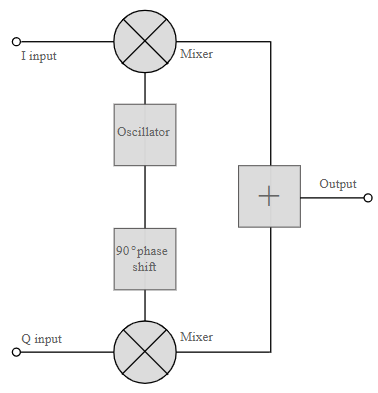
A4) The QAM modulator essentially follows the idea that can be seen from the basic QAM theory where there are two carrier signals with a phase shift of 90° between them. These are then amplitude modulated with the two data streams known as the I or In-phase and the Q or quadrature data streams. These are generated in the baseband processing area.
Basic QAM I-Q modulator circuit
The two resultant signals are summed and then processed as required in the RF signal chain, typically converting them in frequency to the required final frequency and amplifying them as required.
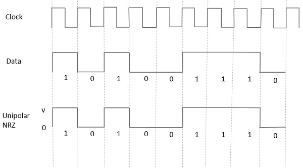
Fig 6 QAM Modulator
It is worth noting that as the amplitude of the signal varies any RF amplifiers must be linear to preserve the integrity of the signal. Any non-linearities will alter the relative levels of the signals and alter the phase difference, thereby distorting he signal and introducing the possibility of data errors.
Basic QAM I-Q demodulator circuit
The basic modulator assumes that the two quadrature signals remain exactly in quadrature.
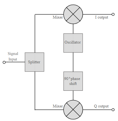
Q5) Explain the demodulation of M-ary QAM?
A5) Systems include circuitry for carrier recovery that often utilises a phase locked loop - some even have an inner and outer loop. Recovering the phase of the carrier is important otherwise the bit error rate for the data will be compromised.
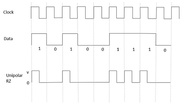
Fig 7 QAM Demodulator
The circuits shown above show the generic IQ QAM modulator and demodulator circuits that are used in a vast number of different areas. Not only are these circuits made from discrete components, but more commonly they are used within integrated circuits that are able to provide a large number of functions.
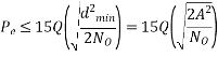
Error Probability
Q6) Explain differential pulse code modulation technique?
A6) Differential pulse code modulation (DPCM) is a procedure of converting an analog into a digital signal in which an analog signal is sampled and then the difference between the actual sample value and its predicted value (predicted value is based on previous sample or samples) is quantized and then encoded forming a digital value.
DPCM code words represent differences between samples unlike PCM where code words represented a sample value.
Basic concept of DPCM - coding a difference, is based on the fact that most source signals show significant correlation between successive samples so encoding uses redundancy in sample values which implies lower bit rate.
Realization of basic concept (described above) is based on a technique in which we have to predict current sample value based upon previous samples (or sample) and we have to encode the difference between actual value of sample and predicted value (the difference between samples can be interpreted as prediction error).
Because it's necessary to predict sample value DPCM is form of predictive coding.
DPCM compression depends on the prediction technique, well-conducted prediction techniques lead to good compression rates, in other cases DPCM could mean expansion comparing to regular PCM encoding.
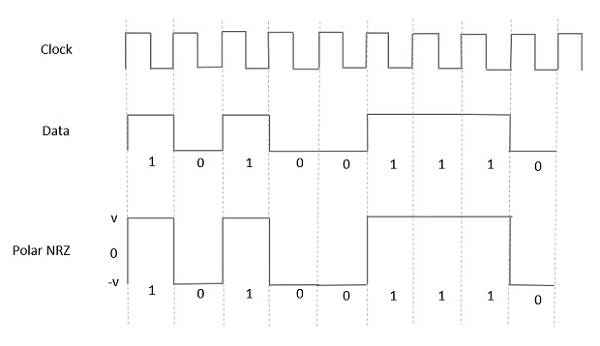
Fig.8: DPCM
Q7) Explain the synchronization in TDM. What are the problems discuss?
A7) There should always be synchronisation in transmitter and receiver. Usually, markers are inserted to indicate the separation between the frames. Synchronisation is obtained due to these marker pulses but the number of channels to be multiplexed is reduced by one. They become N-1.
Crosstalk
In TDM transmission the signal is converted to smooth modulating waveform when passed through the baseband filter. The baseband value passes through the values of all the individual samples.
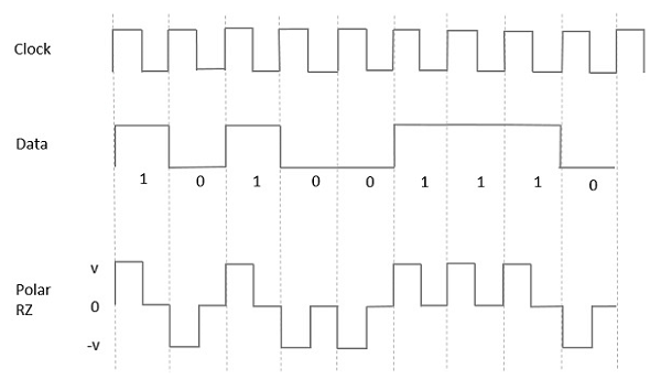
Fig 9 TDM transmission with baseband filtering and its waveform
Due to this baseband filter crosstalk arises in between two samples. This interference can be reduced by increasing the distance between individual signal samples. The minimum distance required to avoid crosstalk between two samples is called as guard time.

Fig 10 Applied rectangular pulse and its response
From above figure we see that even after the pulse is removed the response decays from its value A and then takes longer period. The guard time Tg represents minimum pulse spacing. After guard time end the pulse tail is less than Act.
Act = A
B= Bandwidth of signal
Q8) Twelve different message signals each of bandwidth 20kHz are to be multiplexed and transmitted. Determine the minimum bandwidth required for PAM/TDM system?
A8) No. of channels N =12
Bandwidth of each channel fm = 20kHz
Minimum bandwidth required to avoid crosstalk is = Nfm = 20 x 12 = 240kHz
Q9) Discuss slope overload?
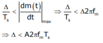
A9) Slope Overload: Slope overload distortion occurs when the analog input signal changes at a faster rate than the DAC can maintain it, the slope of the analog signal is greater than the delta modulator can maintain. In general, when the slope of stair case is less than (or) equal to modulating signal, the slope overloading occurs. Increasing the clock frequency reduces the probability of slope overload occurring. General method to reduce the slope overload is to increase the magnitude of the size. Assume the input for Delta modulation be f(t) = A cos ωmt.
If the step size used in the Delta modulation system is ‘Δ’, then the maximum (rate of rise) slope over load is / Ts
Q10) What is granular noise?
A10) In general, Granular noise occurs
There is a need to have a large step size to accommodate a wide dynamic range, whereas small step size is required for the accurate representation of relatively low-level signals.
Therefore, a granular noise can be removed by taking a small resolution of step size and a slope over load distortion can be removed by taking a large resolution.


