Unit-4
Band-pass Modulation and Demodulation
Q1) Explain the types of digital modulations?
A1) Digital Modulation provides more information capacity, high data security, quicker system availability with great quality communication. Hence, digital modulation techniques have a greater demand, for their capacity to convey larger amounts of data than analog modulation techniques.
There are many types of digital modulation techniques and also their combinations, depending upon the need. Of them all, we will discuss the prominent ones.
ASK – Amplitude Shift Keying
The amplitude of the resultant output depends upon the input data whether it should be a zero level or a variation of positive and negative, depending upon the carrier frequency.
FSK – Frequency Shift Keying
The frequency of the output signal will be either high or low, depending upon the input data applied.
PSK – Phase Shift Keying
The phase of the output signal gets shifted depending upon the input. These are mainly of two types, namely Binary Phase Shift Keying BPSK and Quadrature Phase Shift Keying QPSK, according to the number of phase shifts. The other one is Differential Phase Shift Keying DPSK which changes the phase according to the previous value.
M-ary Encoding
M-ary Encoding techniques are the methods where more than two bits are made to transmit simultaneously on a single signal. This helps in the reduction of bandwidth.
The types of M-ary techniques are −
M-ary ASK
M-ary FSK
M-ary PSK
Q2) Compare ASK, FSK and PSK?
A2)
Parameter | ASK | FSK | PSK |
Constant Parameter | Frequency, phase of carrier | Amplitude, phase of carrier | Amplitude, frequency of carrier |
BW | Low | High | Low |
Noise | High | Low | Low |
S/N ratio | Low | High | High |
Data Rate | less | less | high |
Q3) Explain with waveform ASK?
A3) In ASK, the amplitude of the signal is varied to represent the signal levels, while frequency and phase remains constant. In order to represent 0 and 1, two different amplitudes are used.
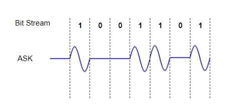
Fig. 1: ASK
Q4) Explain PSK with its waveform?
A4) In this, the phase of the carrier signal is modulated to represent the signal levels, while amplitude and frequency remains constant.
Binary Phase Shift Keying (BPSK) is the simplest form of PSK where there are two signal elements represented by two different phases.
In Quadrature PSK (QPSK), two bits of information are transmitted per symbol by using four different phases.
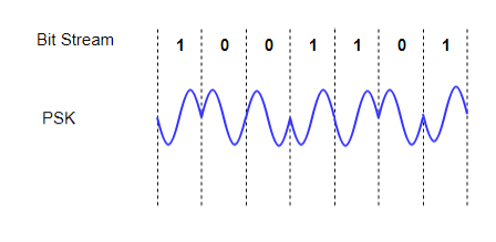
Fig. 2: ASK
Q5) Explain the method of generation of FSK?
A5) FSK Modulator
The FSK modulator block diagram comprises of two oscillators with a clock and the input binary sequence. Following is its block diagram.

Fig.4: FSK modulator
The two oscillators, producing a higher and a lower frequency signals, are connected to a switch along with an internal clock. To avoid the abrupt phase discontinuities of the output waveform during the transmission of the message, a clock is applied to both the oscillators, internally. The binary input sequence is applied to the transmitter so as to choose the frequencies according to the binary input.
FSK Demodulator
There are different methods for demodulating a FSK wave. The main methods of FSK detection are asynchronous detector and synchronous detector. The synchronous detector is a coherent one, while asynchronous detector is a non-coherent one.
Q6) Explain generation of BPSK signal?
A6) Generation
To generate the BPSK signal, we build on the fact that the BPSK signal is a special case of DSB-SC modulation. Specifically, we use a product modulator consisting of two components.
(i) Non-return-to-zero level encoder, whereby the input binary data sequence is encoded in polar form with symbols 1 and 0 represented by the constant-amplitude.
(ii) Product modulator, which multiplies the level encoded binary wave by the sinusoidal carrier of amplitude to produce the BPSK signal. The timing pulses used to generate the level encoded binary wave and the sinusoidal carrier wave are usually, but not necessarily, extracted from a common master clock.
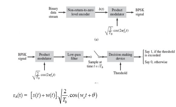
Fig. 6: Generation of BPSK SIgnal
Q7) Explain detection of BPSK signal?
A7) Detection
To detect the original binary sequence of 1s and 0s, the BPSK signal at the channel output is applied to a receiver that consists of four sections
(a)Product modulator, which is also supplied with a locally generated reference signal that is a replica of the carrier wave
(b)Low-pass filter, designed to remove the double-frequency components of the product modulator output (i.e., the components centered on) and pass the zero-frequency components.
(c)Sampler, which uniformly samples the output of the low-pass filter at where; the local clock governing the operation of the sampler is synchronized with the clock responsible for bit-timing in the transmitter.
(d)Decision-making device, which compares the sampled value of the low-pass filters output to an externally supplied threshold, every seconds. If the threshold is exceeded, the device decides in favour of symbol 1; otherwise, it decides in favour of symbol 0. levels.
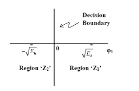
Fig. 7: Decision-making device
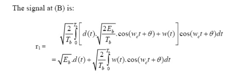
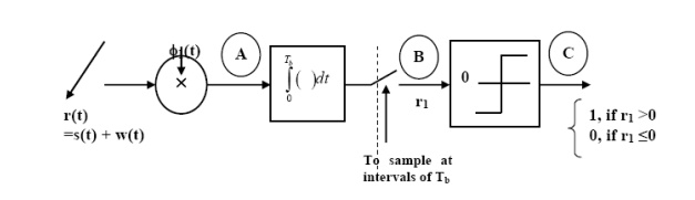
Fig.8: Decision-making device
Q8) Explain generation of QPSK?
A9) Generation
The QPSK Modulator uses a bit-splitter, two multipliers with local oscillator, a 2-bit serial to parallel converter, and a summer circuit.
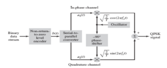
Fig.10: QPSK generation
At the modulator’s input, the message signal’s even bits (i.e., 2nd bit, 4th bit, 6th bit, etc.) and odd bits (i.e., 1st bit, 3rd bit, 5th bit, etc.) are separated by the bits splitter and are multiplied with the same carrier to generate odd BPSK (called as PSKI) and even BPSK (called as PSKQ). The PSKQ signal is anyhow phase shifted by 90° before being modulated.
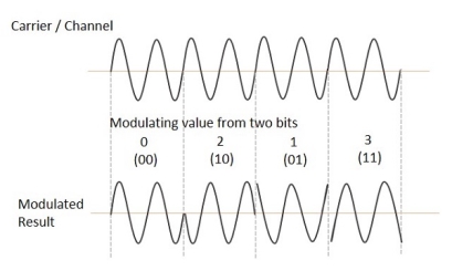
The QPSK waveform for two-bits input is as follows, which shows the modulated result for different instances of binary inputs.
Q9) Explain detection of QPSK?
A10) The QPSK Demodulator uses two product demodulator circuits with local oscillator, two band pass filters, two integrator circuits, and a 2-bit parallel to serial converter.
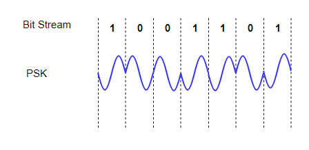
Fig.11: QPSK detectors
The two product detectors at the input of demodulator simultaneously demodulate the two BPSK signals. The pair of bits are recovered here from the original data. These signals after processing are passed to the parallel to serial converter.
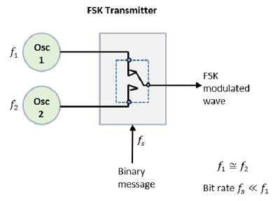
Fig.12: QPSK output


