EIM
Unit-7Digital Measurements Q1) Write a short note on digital voltmeter?
Figure 1. Digital Voltmeter It is basically the signal that is the voltage to be measured.
Pulse generator: Actually, it is a voltage source. It uses digital, analog or both techniques to generate a rectangular pulse. The width and frequency of the rectangular pulse is controlled by the digital circuitry inside the generator while amplitude and rise and fall time is controlled by analog circuitry.AND gate: It gives high output only when both the inputs are high. When a train pulse is fed to it along with rectangular pulse, it provides us an output having train pulses with duration as same as the rectangular pulse from the pulse generator. Q2) Explain the working of Digital Voltmeter?Unknown voltage signal is fed to the pulse generator which generates a pulse whose width is proportional to the input signal. Output of pulse generator is fed to one leg of the AND gate. The input signal to the other leg of the AND gate is a train of pulses. Output of AND gate is positive triggered train of duration same as the width of the pulse generated by the pulse generator. This positive triggered train is fed to the inverter which converts it into a negative triggered train. Output of the inverter is fed to a counter which counts the number of triggers in the duration which is proportional to the input signal i.e. voltage under measurement. Thus, counter can be calibrated to indicate voltage in volts directly. Q3) Write a short note on digital multimeter?
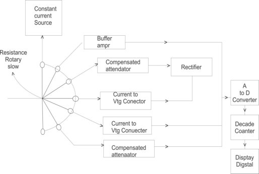
Figure 2. Digital Multimeter A Multi meter the most common measuring instrument. The name comes from multiple meters. There are two common types of Multi meter. The multi-meter (DMMs) are the most common Measurement readings are displayed as numerical values on the LCD display. The display also alerts you to any pertinent symbols and warning. Digital meters on the other hand offer high accuracy have a high i/p impedance and are smaller in site. An instrument which is capable of measuring a.c. and d.c voltages a.c and d.c current and resistances over several range is called digital multi-meter. The various measurement possible by DMM are resistance a.c voltage and current d.c voltage and current. The selection of the parameter is possible with the help of rotary switch connected to input probes of DMM.D.C current measurement: The rotary switch is in position 4 and unknown d.c current is applied across i/p probes this voltage is given to ADC without rectification as this is proportional to d.c current ADC display it in amperes on digital display.D.C voltage measurement: The rotary switch is in position 5 and unknown voltage is applied across i/p probes it is attenuated and directly given to ADC display it in volts.In digital multi-meter the input signal that is ac or dc voltage, current, resistance, temperature, or any other parameter is converted to dc voltage within the range of the ADC. The analog to digital converter converts the pre-scaled dc voltage into its equivalent digital numbers which will be displayed on the display unit. Q4) What is a universal counter?A universal Counter is a one- piece combined unit that has in it all the circuits for measurement of frequency, time period, frequency ratio etc. Desired functions can be selected using the function switch. Q5) With help of block diagram explain the working of universal counter?
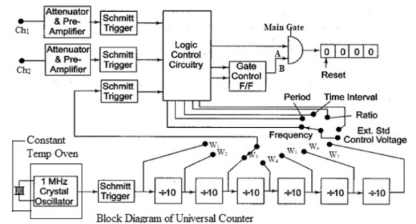
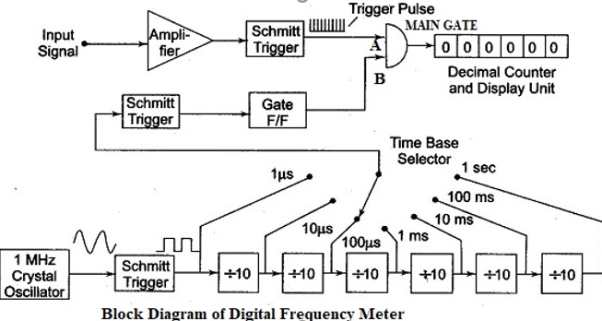
Figure 3. Universal Counter There are two channels for the input named as chl and ch2. The input signal reaches the preamplifiers through attenuators. Two Schmitt trigger circuits are fed from the output of the two preamplifiers. The two Schmitt triggers present their outputs to the Logic Control Circuitry. The second channel is meant for frequency ratio and multiple ratio measurement. The block Logic Control Circuitry contains logic gates that are enabled or disabled depending on the selection of the function by the function switch and on the status of the inputs to the L.C.C. The output from the Logic Control Circuitry directly reaches one input of the Main Gate. The Main Gate output drives a decimal counter. The output of the decimal counter drives a decoder driver which drives the display unit. The second input to the Main Gate is derived from Gate Control Flip Flop. The gate control flip-flop is controlled by the output of the logic control circuit. The crystal oscillator called the clock oscillator generates an output voltage at 1 MHz, and is sinusoidal in nature. The crystal oscillator offers excellent frequency stability. The output of the crystal oscillator is given to a Schmitt trigger circuit. This converts the sinusoidal voltage of the crystal oscillator in to train of pulses. The rate of the pulse train offered by the Schmitt trigger will be equal to the frequency of the clock oscillator. The output from the Schmitt trigger is presented to a chain of decade dividers. The output of the Schmitt trigger, as well as the outputs of the decade dividers is brought over the ways of a selector switch. The selector switch has seven ways w1 to w7, and we can select pulses from 1 μs to 1 s. These are the time base pulses to the logic control circuitry, again through another Schmitt trigger. Q6) Write a short note on digital frequency meter?The input signal whose frequency is to be measured (counted) is given to the first channel of the universal counter. It reaches the preamplifier through the attenuator. The amplified signal reaches the Schmitt trigger where it is converted into square wave. A differentiator circuit, along with a clipper produces a train of pulses. This train of pulses is separated by the period of the input signal. These pulses are applied to the A input of the AND gate. The time base selector switch is selected to the appropriate range. The time base pulses are given to the Schmitt trigger from where they reach the gate control flip-flop. The first- time base pulse triggers gate control flip-flop and its output goes high. Therefore, B input of the AND gate will be held at high state, thus enabling the AND gate. Therefore, the input signal pulses present at input A of the AND gate can reach the decimal counter. The count starts and the AND gate will be enabled if its B input is high. For the second time base pulse, the gate control flip-flop toggles and its output goes low. Hence the B input of the AND gate goes low. The AND gate is disabled, preventing the input signal pulses from reaching the decimal counter.
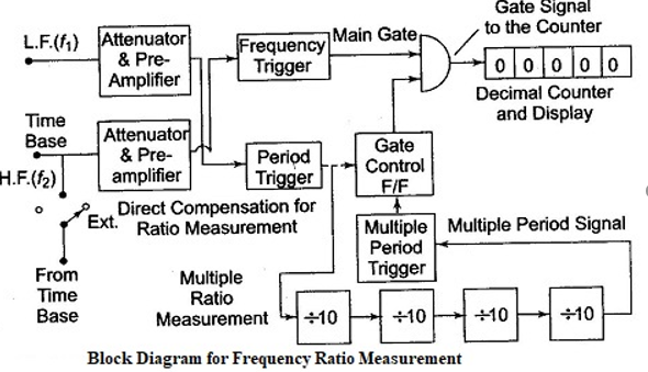
Figure 4. Digital Frequency Meter Thus, the decimal counter will count the input pulses only for the period between the first-time base pulse and the second time base pulse. If we select the time base pulse with 1 second duration, the decimal counter counts the number of input pulses presented during that 1 second. This count will be displayed on the display which is the frequency of the input signal. Q7) Explain measurement of frequency ratio? The frequency ratio measurement section is presented in the figure. The aim is to measure the ratio of two frequencies. Normally one frequency will be higher than the other. The low frequency will be employed as the gating signal and high frequency signal is used for counting.
Figure 5. Measurement of Frequency Ratio From the block diagram the low frequency signal, fL is applied to channel 1. The high frequency signal fH is given to channel 2. The channel 1 preamplifier's output reaches as period trigger to the gate control flip-flop. The channel 2 preamplifier's output reaches the A input of the Main gate. The gate control flip-flop is triggered by the input from channel 1. The output of this flip-flop is applied at the B input of the main gate. The number of cycles of the high frequency signal fH, that occur during the period of the low frequency signal fL are counted and displayed by the instrument. In case of multiple ratio measurement, the period of the low frequency signal can be enhanced by the use of a chain of decimal dividers. Q8) Explain time period measurement? For time period measurement block diagram, the gate control flip-flop is controlled by the input signal presenting the start and stop signals through the two input channels. That is the gating signal is obtained from the input signal whose time period is not known. This input signal controls the enabling and disabling of the main gate.
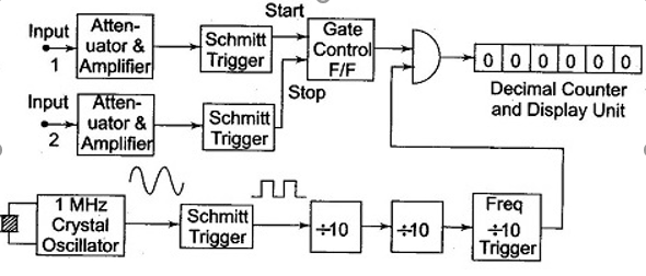
Figure 6. Time Period MeasurementThe other input to the main gate is derived from the decade dividers connected through the Schmitt trigger to the clock oscillator. Now the gate will pass the trigger pulses from the divider to the decimal counter, which counts and displays. The decimal counter counts the number of pulses that occur during one period of the unknown input signal. Q9) What are the applications of digital voltmeter? Digital Voltmeter is used to know the actual voltage of different components. DVM is widely used to check if there is power in the circuit, such as mains outlet. Knowing the voltage across a circuit, current can be calculated. Q10) What are the applications of frequency meter? The equipment’s like radio can be tested using a digital frequency meter It can measure parameters like pressure, strength, vibrations, etc.
|
Pulse generator: Actually, it is a voltage source. It uses digital, analog or both techniques to generate a rectangular pulse. The width and frequency of the rectangular pulse is controlled by the digital circuitry inside the generator while amplitude and rise and fall time is controlled by analog circuitry.AND gate: It gives high output only when both the inputs are high. When a train pulse is fed to it along with rectangular pulse, it provides us an output having train pulses with duration as same as the rectangular pulse from the pulse generator. Q2) Explain the working of Digital Voltmeter?
|
|
|
|
|
0 matching results found

