UNIT 3
Timing Circuits and Oscillators
Q1.What do you understand by RC-timing circuits?
A1. Time Constant: T = R C
The time constant calculations below are needed for designing timing circuits.
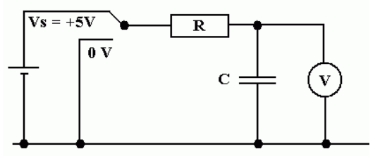
Here is a timing circuit. Click the switch the start charging or discharging
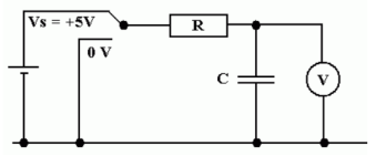
Fig: RC timing Circuit
Q2. Explain the IC 555 work and its application?
A2.
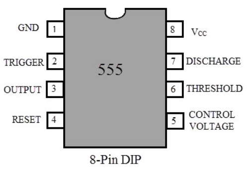
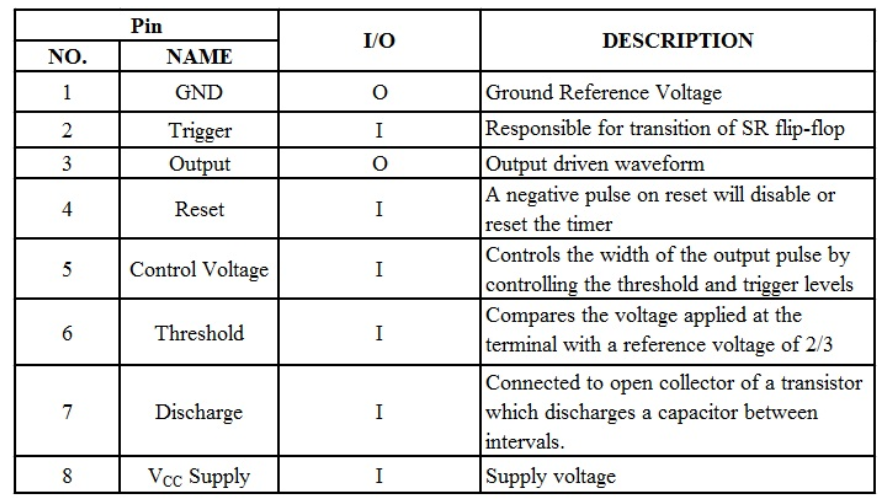
Some of the important features of the 555 timer are
Different Modes Of Operation
Generally, the 555 timer can be operated in three modes: Astable, Monostable (or one-shot) and Bistable.
Astable ModeIn this mode, the 555 work as a free running mode. The output of astablemultivibrator will continuously toggle between low and high, there by generating a train of pulse, which is why it is known as pulse generator.
It is a best example for a perfect square wave generator. They are used as an inverter and also used in many of the internal part of the radio. Selecting a Thermistor as a timing resistor allows the use of the 555 in a temperature sensor.
Monostable ModeIn the monostable mode, as the name suggests, it stays in its stable state until and unless an external trigger is applied. In this mode, the 555 functions as a “one-shot” pulse generator. The best application of a monostable is to introduce a time delay in to a system.
Applications comprise many things viz., timers, missing pulse detection also included bounce free switches, touch switches as well as frequency divider, capacitance measurement and pulse-width modulation (PWM) and many more.
Q3. Write a short note on Positive feedback?
A3. An oscillator is a device that generates AC output signals without any input AC signal. A fraction of output is feedback to the input.
A= Gain of amplifier (open 100Þ)
Β= Feedback gain
V= input signal
Av= Amplified signal at output
A fraction of the signal βAv is feedback to the input. It must be ensured by the feedback circuit that feedback signal βAv must be in phase with input signal v.
Now C is connected to A and input signal is removed. The only signal which is to drive the amplifier is feedback (βAv)
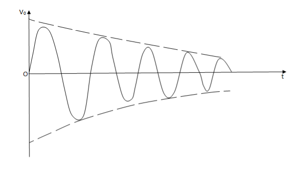
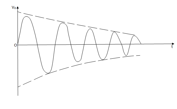
Case (1)- If βA<1, βAv>V and the output signal will die out (damped oscillation)
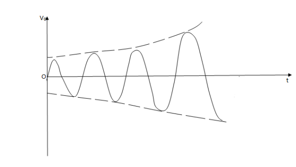
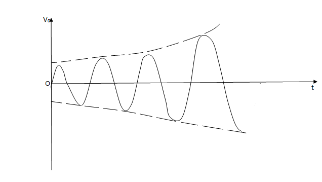
Case (2)- If βA>1, βAv>V and the output signal will built up (growing oscillations)
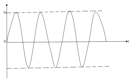
Case(3)- If βA=1, no change occurs in the output and we get an output with constant magnitude (undamped or Sustained oscillations
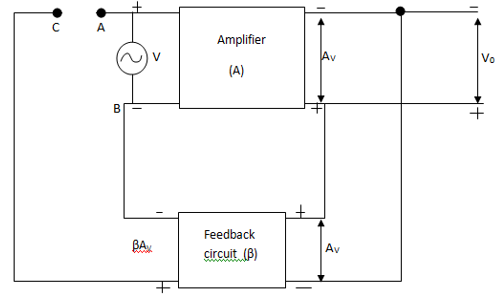
Thus to obtain Sustained oscillations, the loop gain βA of a positive feedback amplifier must be unity(1).
Derivation of overall gain of positive feedback amplifier
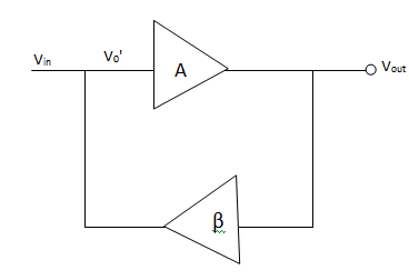
V= Vin + βVout
Vout = Av1
Vout = A(Vin+βVout )
Vout (1-Aβ)=AVin
Or 

AF= 
Where AF is the gain with feedback
Q4. Explain the principle of Barkhausen's criteria for oscillation?
A4. Barkhausen Condition – Condition that are required to be satisfied to operate the circuit as an oscillator are called as Barkhausen condition.
In oscillator circuit there is no input signal hence the feedback signal it say should be sufficient to maintain the oscillations.
Barkhausen condition states that


where n=0,1,2,……..
Types of Oscillator- An oscillator circuit is usually made up of transistor. A transistor can work as an oscillator to produce undamped continuous oscillations of any desired frequency it oscillatory and feedback circuits are properly connected to it. The oscillators differ only in the way of feedback to supply losses to the oscillatory circuit. The following are the important oscillators-
Q5. Give a brief description on Wein bridge oscillator?
A5. Wein Bridge Oscillator- In this, phase shift is produced by using 2 transistors. Each produces a phase shift of 180° and hence phase shift of 360° is obtained
It is a 2 stage amplifier with R-C bridge circuit. The bridge circuit has 4 arms each containing components R1C1 in Series, R2 C2 in parallel, R3 and R4. Q1 acts as an oscillator and amplifier where as Q2 Serves as an inverter
When circuit is closed through switch S, the bridge circuit produces the oscillations of frequency whose expression is given by-
F= 
If R1=R2=R and C1= C2 = C then
F = 
A total phase shift of 360° is obtained at the output of the second transistor. A fraction of this output energy is fed back to the oscillatory circuit (bridge) at the upper terminal. This positive feedback is to meet with the losses in the oscillator and hence undamped oscillations are produced.
Advantages-
Disadvantages-
Q6. In the RC network of a Weinbridge oscillator R1 = R2 = 200kΩ, determine the value of each of the capacitor to obtain a frequency of 5kHz.
A6.
F = 
F = 5kHz, = 5000Hz
R1= R2= 200kΩ = 200×103Ω
5000 = 
C =  = 159.15 pF
Expression for feedback factor (β) and frequency (f)
In order to obtain expression for β and f, we will consider only frequency sensitive arms AD and CD as shown in figure below
Vin is actually the output voltage V0which comes from the amplifier output and voltage across R2C2acts as a feedback voltage VF
Feedback factor β= 
Let impedance of arm AD be Z1 and that of DC be Z2
Therefore VF =  ×Vin{ using voltage divider}
β =  =
=  ………….(1)
Z1= R1 +  =
=  …………..(2)
Z2 = R2 || Xc2=  =
=  ………….(3)
Substituting equation (2) and (3) in (1)
β = 
Substituting jw = S
β = 
β = 
β = 
β = 
Resubstitute jw = S , S2 = j2 w2 = -w2
β = 
β = 
Rationalize the above equation
β =  ……………(4)
The phase shift introduced by the wien bridge circuit at the desired output frequency should be 0°. For that the imaginary part of equation (4) should have a zero value.
wC1R2(1-w2R1R2C1C2) = 0
w2R1R2C1C2 = 1
 =
= 
W = 
F = 
The above equation is the expression for the oscillator frequency.
If we substitute R1 = R2 = R and C1 = C2 = C
F =  or w =
For β, if R1 = R2 = R, C1= C2 = C
β = 
Substituting
W = 
β =  =
=  =
= 
Thus at the oscillator frequency F, the value of feedback factor β is 
Q7. Explain the work faction of RC phase Shift Oscillator?
A7. A typical RC phase shift oscillator using transistor as an active device is shown below
The output V0of the single stage CE amplifier has been connected as an input to the RC phase shift network. The output of the phase shift network is connected at the input of the amplifier.
As the amplifier is CE type it introduces phase shift of 180°. The phase shift network will introduce an additional 180° phase shift
Resistance R3 + Zi = R
Where Ziis input impedance of CE amplifier
Zi = hie || (R1 || R2)
Therefore R1 and R2 are large, we can neglect them
Therefore Zi = hie
So R3 = R- hie
Frequency of Oscillations is given by
F =  *
*  where k =

Derivation:-For this transistor is replaced by hybrid model and current source is replaced by voltage source.
Replace R3 + hie = R and Rc= KR
Apply KVL tw various loops
Loop I therefore hfeIbRc+ I1Rc +  + I1 R – I2 R =0
where RC = KR
hfeIbkR+ I1kR +  + I1 R – I2 R =0
Put S = jw
I1 – I2R = - I2R = - hfeIbkR ………(1)
Loop 2 :-  + I2R – I3R + I2R – I1R = 0
Put S = jw
I2 – I1R – I3R =0 …………….(2)
Loop 3:- + I3R + I3R – I2R = 0
Put S = jw
I3 – I2R = 0 ……………..(3)
Rearranging (1), (2) and (3)
I1 – I2R = - hfeIbkR
-I1R + I2 – I3R = 0
And -I2R + I3 = 0
= 0
Solving above equation for I3 using Cramer’s rule
 =
= 
I3= 
∆ =  - R2
- R2 -R2
-R2
∆ =  -
-  -
- 
∆ = 
Simplifying we get,
∆ = 
 =
= 
 = -hfeIbkR × R2 = - K hfeIb R3
I3=  ………..(4)
 Aββ =
Aββ =  but IC = hfeIb
β = 
gain A =  = hfe
= hfe
therefore Aβ =  × hfe =
Substituting valve of I3 from (4)
Aβ = 
Put S = jw , then S2= -w2, S3 = -w2, S3 = -jw3
Aβ = 
Dividing the numerator and denominator by –jw3R3C3 we get,
Aβ = 
Substituting  = X
= X
Aβ = 
According to Barkhausen Criterion <Aβ = 0° for that the imaginary term of the denominator should be equal to 0
i.e. X3-4kx-6x = 0
X(X2 -4k -6) = 0
X=0 or X2 = 4k + 6 or X = 
 =
= 
Or W = 
Or F = 
This is the required expression of frequency