Module-6
Reciprocating Compressors
Question 1: What is compressor? Explain its types.
Answer: A compressor is a mechanical device that increases the pressure of a gas by reducing its volume. (The fluid here is generally air since liquids are theoretically incompressible).
Classification of compressor:
There are mainly two types of Compressors-
2. Rotary compressor
Question 2: What is Reciprocating compressor? Explain its types.
Answer: In a reciprocating compressor, a volume of gas is drawn into a cylinder; it is trapped, and compressed by piston and then discharged into the discharge line. The cylinder valves control the flow of gas through the cylinder and these valves act as check valves.
Reciprocating compressors can be Single acting or double acting.
Reciprocating compressor types:
Compression is done in single stage or by single cylinder only and it is used for generation of low-pressure air.
2. Double–stage Reciprocating Compressor:
It is a compressor that produces highly pressurized air and mostly it is used nowadays in heavy duty mechanical devices.
Question 3: A single stage double acting air compressor of 150KW power takes air in at 16 bar & delivers at 6 bar. The compression follows the law PV1.35 = C. the compressor runs at 160rpm with average piston speed of 150 m/min. Determine the size of the cylinder.
Given data
Power (P) = 150KW
Piston speed (2lN) = 150m /min
Speed (N) = 160rpm 160/6 0 = 2.7rps
Pressure (P1) = 1bar = 100 KN/m2
Pressure (P2) = 6bar = 600 KN/m2
PV1.35 = C, n = 1.35
Hence it is a polytropic process.
Answer:
It is given that
2lN = 2.5m/s


Since 


We know that
Power (P)=2×W×N (for double acting) For polytropic process, work done (W) is


150 = 2 × 82.899  × 2.7
× 2.7
 = 0.3350
d = 0.57M
Question 4: What is principle single stage reciprocating compressor? Explain with example.
Answer: Working Principle:
•Here, pressure is increased by means of variation in the volume of cylinder obtained by a moving piston.
Construction:
•Single stage single acting air compressor consists of a piston, which reciprocates inside a cylinder having connecting rod and crank mechanism.
•There are inlet and delivery valves mounted in the head of cylinder.
•The inlet and delivery valves are of pressure differential type i.e.; they operate as a result of pressure difference across the valves.
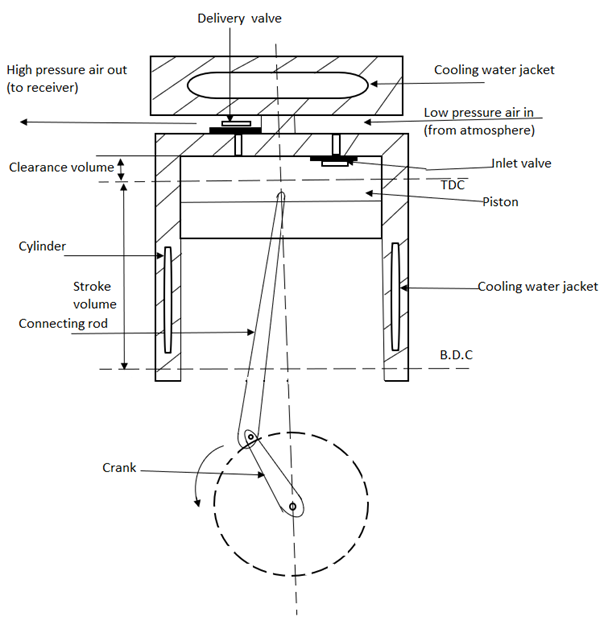
Figure 1: Single stage reciprocating compressor
Working:
Working of single stage reciprocating air compressor is completed in two strokes.
a). Suction Stroke:
b). Compression Stroke:
Question 5: Explain two stage reciprocating compressor with diagram.
Answer: Two stage reciprocating compressor:
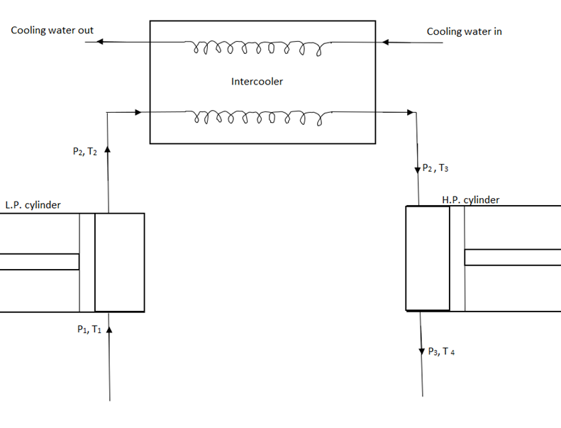
Figure 2: Two stage reciprocating compressor
Question 6: What are the effects of intercooling on Brayton cycle?
Answer: Effects of intercooling on Brayton cycle:
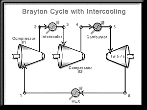
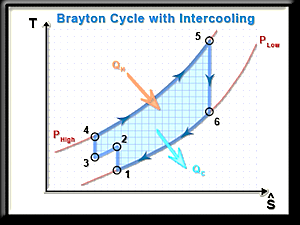
Figure 3: Intercooling on Brayton cycle
For ideal cycle with intercooling
Wc = C p (T 2a -T 1) + (T 2 -T 2b)
Heat supplied
Qs = C p (T 3 -T 2)
Work by turbine: W t =C p (T 3 -T 4)
Thermal efficiency of gas turbine cycle with intercooling:

Question 7: A single stage single acting reciprocating air compressor is required to handle 30m3 of free air per hour measured at 1 bar . the delivery pressure is 6.5 bar and the s peed is 450 r.p.m allowing volumetric efficiency of 75%;an isothermal efficiency of 76% and mechanical efficiency of 80% Find the indicated mean effective pressure and the power required the compressor
Answer: Indicated Mean Effective Pressure
We know that isothermal work done


And Indicated work done = Isothermal work done/ Isothermal efficiency

We know that swept volume of the piston

Indicated mean effective pressure  Indicated work done/ Swept volume


The power required to drive the compressor
We know that work done by the compressor = 

Therefore the power required to drive the compressor 
Question 8: Derive the expression for maximum and minimum work for multistage compressor:
Answer: Maximum work is saved in a two-stage reciprocating air compressor with perfect intercooling. Work required to be done by a two-stage reciprocating air-compressor with complete intercooling is given by-

If the intake pressure and delivery pressure are constant, then the least value of the intermediate or intercooler pressure may be obtained by differentiating the above equation with respect to intercooler pressure. At this value of intercooler pressure, the work required to drive the compressor is minimum.


Now considering  (a constant)


For minimum work input to the compressor of a two stage air compressor, Pressure ratio in each stages are same,

Work required to be done by a two-stage reciprocating air-compressor with complete intercooling is given by-

Minimum power required for compression is given by-

Question 9: A two stages, single acting air compressor compresses air to 20bar. The air enters the L.P cylinder at 1bar and 27oc and leaves it at 4.7bar. The air enters the H.P. cylinder at 4.5bar and 27oc. the size of the L.P cylinder is 400mm diameter and 500mm stroke. The clearance volume In both cylinder is 4% of the respective stroke volume. The compressor runs at 200rpm, taking index of compression and expansion in the two cylinders as 1.3, estimate
1. The indicated power required to run the compressor; and
2. The heat rejected in the intercooler per minute.
Given, Pressure (P4)= 20bar, Pressure (P1) = 1bar = 1× 10⁵ N/m2 Temperature (T1) = 27oC = 27+273 = 300K Pressure (P2) = 4.7bar, Pressure (P3) = 4.5bar, Temperature (T3) = 27oC = 27+273 = 300K Diameter (D1) = 400mm 0.4m Stroke (L1) = 5 00mm = 0.5m, K = 0.04, N = 200rpm ; n = 1.3
Answer: We know the swept volume of the L.P cylinder

And volumetric efficiency


Volume of air sucked by air pressure compressor


And volume of air sucked by H.P compressor

We know that indicated work done by L.P compressor,


And indicated work done by H.P compressor,


Total indicated work done by the compressor,
W = WL + WH = 2123.3 + 2034 .5 = 4157.8 KJ/min
Indicated power required to run the compressor= 4157.8 / 60 = 69.3KW
Question 10: Explain different parts and principle of operation of reciprocating compressors with diagram.
Answer: Different parts of reciprocating compressor:
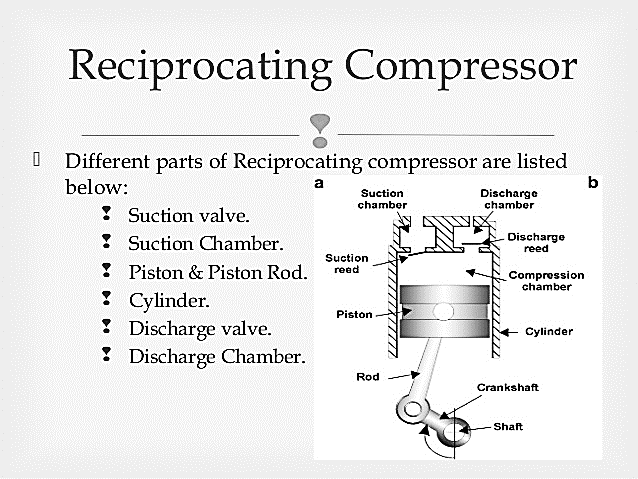
Figure 4: Reciprocating compressor
Principle of Operation:
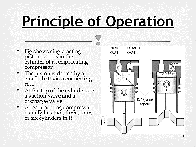
Figure 5: Operation of Reciprocating compressor