Unit-3
Fluid Kinematics
Q1) Define control volume phenomenon in fluid mechanics.
A1) An open system, or a control volume, as it is often called, is a properly selected region in space.
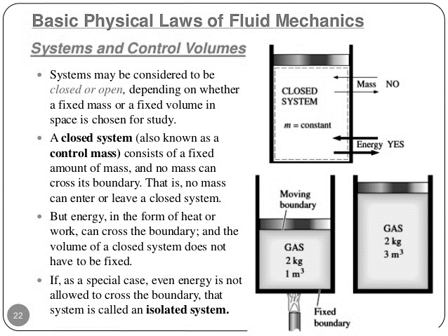
Fig 1: Control Volume
A control volume usually encloses a device that involves mass flow such as a compressor, turbine, or nozzle. Flow through these devices is best studied by selecting the region within the device as the control volume. Both mass and energy can cross the boundary of a control volume.
In continuum mechanics and thermodynamics, a control volume is a mathematical abstraction employed in the process of creating mathematical models of physical processes. In an inertial frame of reference, it is a fictitious volume fixed in space or moving with constant flow velocity through which the continuum flows.
A large number of engineering problems involve mass flow in and out of a system and, therefore, are modelled as control volumes.
A water heater, a car radiator, a turbine, and a compressor all involve mass flow and should be analyzed as control volumes (open systems) instead of as control masses (closed systems).
In general, any arbitrary region in space can be selected as a control volume. There are no concrete rules for the selection of control volumes, but the proper choice certainly makes the analysis much easier.
Q2) Define the control surface in fluid mechanics.
A2) The boundaries of a control volume are called a control surface, and they can be real or imaginary. In the case of a nozzle, the inner surface of the nozzle forms the real part of the boundary, and the entrance and exit areas form the imaginary part, since there are no physical surfaces there.
The surface of the control volume is referred as a control surface and is a closed surface. The surface is defined with relative to a coordinate system that may be fixed, moving or rotating. Mass, heat and work can cross the control surface and mass and properties can change with time within the control volume.
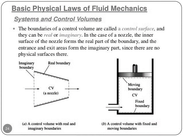
Fig 2: (A) real and imaginary boundaries and (B) with fixed and moving boundaries
Q3) Mention the application of continuity equation.
A3) Application of Continuity equation:
1) We can apply the principle of continuity to pipes with cross sections which change along their length.
A liquid is flowing from left to right and the pipe is narrowing in the same direction. By the continuity principle, the mass flow rate must be the same at each section - the mass going into the pipe is equal to the mass going out of the pipe.
So, we can write-

As we are considering a liquid, usually water, which is not very compressible, the density changes very little so we can say-

This also says that the volume flow rate is constant or that
Discharge at section 1 = Discharge at section 2


As the area of the circular pipe is a function of the diameter, we can reduce the calculation further,


2) Another example is a diffuser, a pipe which expands or diverges as in the figure below:
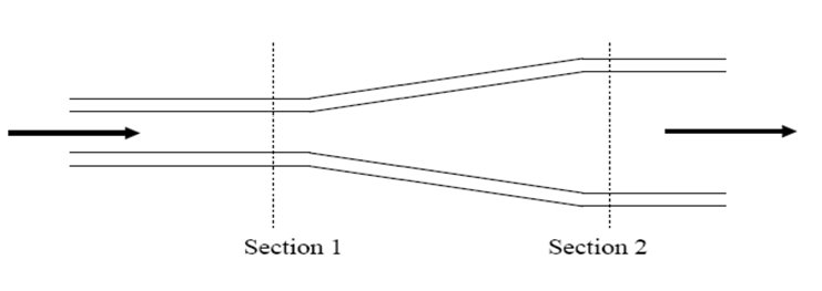
Fig 3: A pipe which diverges
3) The continuity principle can also be used to determine the velocities in pipes coming from a junction.
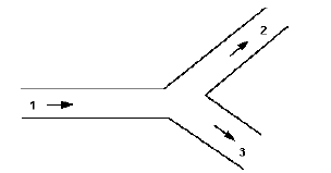
Fig 4: A pipe with a junction
Total mass flow into the junction = Total mass flow out of the junction

When the water flow is incompressible, (Example- water)


Q4) Mention some examples of momentum equations.
A4) The momentum equation is used to determine the resultant force exerted on the boundaries of a flow passage by a stream of flowing fluid as the flow changes its direction or the magnitude of velocity or both.
Following are the practical application of momentum equation:
(1) Flow though bends pipes
(2) Jet propulsion and propellers
(3) Fluid flow though stationary and moving plates or vanes.
(4) Non-uniform flow through sudden enlarged pipes.
(5) Hydraulic jump in open channels
Q5) Explain Bernoulli’s Equation and derive its formula.
A5)
Bernoulli’s Equation:
It states that the sum of kinetic, potential and pressure heads of a fluid particle is constant along a streamline during steady flow when compressibility and frictional effects are negligible. i.e., For an ideal fluid, total head of fluid particle remains constant during a steady-incompressible flow.
Or
Total head along a streamline is constant during steady flow when compressibility and frictional effects are negligible.
The total mechanical energy of the moving fluid comprising the gravitational potential energy of elevation, the energy associated with the fluid pressure and the kinetic energy of the fluid motion, remains constant.


Derivation of Bernoulli’s Equation:
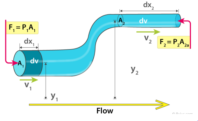
Fig 5: Bernoulli’s Theorem
Assumptions:
Therefore, the work done on the fluid is given as:
dW = F1dx1 – F2dx2
dW = p1A1dx1 – p2A2dx2
dW = p1dV – p2dV = (p1 – p2)dV
We know that the work done on the fluid was due to conservation of gravitational force and change in kinetic energy. The change in kinetic energy of the fluid is given as:
dK=1/2(m2v22)−1/2(m1v12)=1/2ρdV(v22−v12)
The change in potential energy is given as:
dU = mgy2 – mgy1 = ρdVg(y2 – y1)
Therefore, the energy equation is given as:
dW = dK + dU
(p1 – p2)dV = 1/2ρdV(v22−v12) + ρdVg(y2 – y1)
(p1 – p2) = 1/2 ρ(v22−v12) + ρg(y2 – y1)
Rearranging the above equation, we get
p1+1/2ρv12+ρgy1=p2+1/2ρv22+ρgy2
This is Bernoulli’s equation.

It is the important formula.
Q6) Mention one of the applications of Bernoulli’s equation.
A6)
Aerofoil lift
The wings of an airplane (aerofoil) are so designed that its upper surface is more curved than the lower surface and the front edge is broader than the real edge. As the aircraft moves, the air moves faster above the aerofoil than at the bottom as shown in Figure.
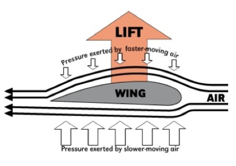
Fig 6: Aerofoil lift
According to Bernoulli’s Principle, the pressure of air below is greater than above, which creates an up thrust called the dynamic lift to the aircraft.
Q7) Define Venturi-meter and derive its formula for coefficient of discharge.
A7): Venturimeter is a device that is used to measure the rate of flow of fluid through a pipe. This device is based on the principle of Bernoulli's Equation.
This device is used to measure the rate of flow (or say flow speed) of the incompressible fluid flowing through a pipe. It works on the principle of Bernoulli’s theorem. It consists of two wider tubes A and A' (with cross sectional area A) connected by a narrow tube B (with cross sectional area a). A manometer in the form of U-tube is also attached between the wide and narrow tubes as shown in Figure. The manometer contains a liquid of density ‘ρm’
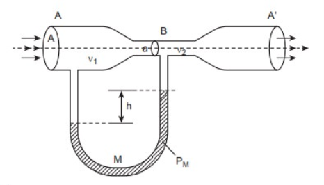
Fig 7: A Schematic diagram of Venturi-meter
Consider a venturimeter is fitted in a horizontal pipe through which fluid (water) is flowing as shown in figure below.
Let a1 = cross-section area of inlet pipe
d1= diameter of inlet pipe
v1 = velocity at inlet pipe
p1 = pressure at inlet pipe
Also,
a2 = cross-section area of throat
d2= diameter of throat
v2 = velocity at throat
p2 = pressure at inlet throat
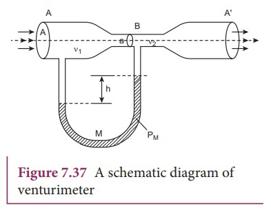
Fig - 8
Applying Bernoull’s equation at section (1) and (2), we get

As the pipe is horizontal, so Z1 = Z2
Hence we get,


(P1 – P2)/ ρg is the difference of pressure heads at section 1 and 2 and is equal to h. So eq (1) becomes.

Now applying continuity at section (1) and (2), we get


Now, Rate of flow of fluid or Discharge (Q) can be stated as:

Substituting value of v2 in this equation, we get

Q is the theoretical discharge under ideal conditions. Actual discharge will be less than this. The actual discharge is given by,

Where Cd is coefficient of venture-meter and its value is always less than 1.
Q8) A Styrofoam cylinder, filled with water, sits on a table. You then poke a small hole through the side of the cylinder, 20 cm below the top of the water surface. What is the speed of the fluid emerging from the hole?
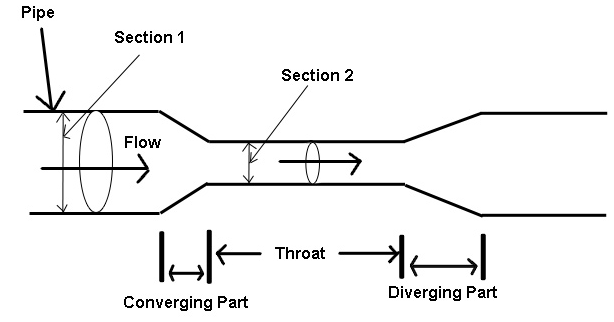
Fig - 9
A8) As usual, begin by drawing a diagram of the situation, as shown in Figure mentioned above. We’re going to apply Bernoulli’s equation, which means identifying two points that we can relate via the equation. Point 2 is outside the container where the hole is, because that is the place where we’re trying to find the speed. Point 1 needs to be somewhere inside the container. Any point inside will do, although the most sensible places are either at the top of the container, where we know the pressure, or inside the container at the level of the hole. Let’s choose a point at the very top, and apply Bernoulli’s equation:

First, we should recognize that, because both of our points are exposed to the atmosphere, we have P1=P2=Patm. The pressure terms cancel in the equation, leaving:

We can cancel factors of density. We are also free to define a zero for our y positions to be anywhere we find convenient. If we say y = 0 at the level of the hole we get y=+20 cm and y2=0, so the equation reduces to:

If we knew the fluid speed at point 1 we could solve for the speed at point 2. This is a good time to bring in the continuity equation, which relates the speeds at the two points A1V1=A2V2 In this case we can say that, because A1 , the cross-sectional area of the cylinder, is so much larger than A2 , the cross-sectional area of the hole, then v1 is much smaller than v2 . Thus, (1/2 v1)2the term is negligible compared to the term (1/2 v2)2. Our equation thus reduces to:

Solving for the speed at which the fluid emerges from the hole gives:

Q9) A wide can of water is filled to height h. At what height from the base should I drill a hole to (i) get the maximum range for the jet that comes out, and (ii) ensure that the jet travels a horizontal distance equal to the vertical distance? (iii) What is the maximum horizontal distance the jet can travel?
A9) Since the can is wide, we can assume that the velocity of the water at the top of the can is zero. If the hole is drilled at height z from the base, then the (horizontal) velocity at the hole is determined by Bernoulli’s equation

Going p back to projectile motion for a moment, a particle dropped from height z takes time t =square root of 2z/g to reach the ground, so it travels a distance R = vt in the horizontal direction. Plugging in the above then gives

i) To make life easy we can maximize the square of R:

ii) This time we solve for

which means z = 4 5 h. Note that the z = 0 solution just means the water comes out at the bottom so it doesn’t travel at all before hitting the ground.
iii) Plugging in the value we found in part (i) into the equation for R, we find that the maximum range is

Q10) A vertical tube of radius 1 cm, open at the top to the atmosphere, contains 2 cm of oil (ρoil = 0.82ρwater) floating on 3 cm of water. What is the gauge pressure (pressure in excess of atmospheric) at the bottom?
A10): Only the depth matters, so that
pgauge = ρoilghoil + ρwaterghwater = ρwaterg(0.82hoil + hwater)
= (1000 kg/m3 )(9.8 m/s 2 )[0.82(0.02 m) + 0.03 m] = 460 Pa.