UNIT-5
Laminar Flow
Q1) Lubricating oil of specific gravity 0.84 and dynamic viscosity 0.137Ns/ pumped at a rate of 0.024
 through a 0.17m diameter 400m long horizontal pipe and the power required to maintain flow.
Given data:
Specific gravity of oil, S=0.84
Dynamic viscosity of oil, μ=0.137Ns/
Rate of flow, Q =0.024
Diameter of pipe, D=0.17m
Length of pipe, L = 400m
A1)
From Hagen-Poiseuille equation, Pressure drop, (


Shear stress at the pipe wall, 


Q2) The Velocity distribution in laminar boundary layer is given by
 . Where,
  Velocity at a distance y from the boundary
 Velocity at a distance δ, the thickness of the boundary layer.
Calculate:
(i) The ratio of displacement thickness to boundary layer thickness
(ii) The ratio of momentum thickness to boundary layer thickness 
A2)
Velocity distribution 
(i) Ratio of displacement thickness to boundary layer thickness 
We know that, 


(ii) The ratio of momentum thickness to boundary layer thickness 


Q3) Explain turbulent through pipes.
A3) Eddy currents are present within the flow and the ratio of the internal roughness of the pipe to the internal diameter of the pipe needs to be considered to be able to determine the friction factor. In large diameter pipes the overall effect of the eddy currents is less significant. In small diameter pipes the internal roughness can have a major influence on the friction factor. The relative roughness of the pipe and the Reynolds number can be used to plot the friction factor on a friction factor chart. The friction factor can be used with the Darcy-Weisbach formula to calculate the frictional resistance in the pipe. Between the Laminar and Turbulent flow conditions (Re 2300 to Re 4000) the flow condition is known as critical. The flow is neither wholly laminar nor wholly turbulent. It may be considered as a combination of the two flow conditions. The friction factor for turbulent flow can be calculated from the Colebrook-White equation:

Turbulence is caused by excessive kinetic energy in parts of a fluid flow, which overcomes the damping effect of the fluid's viscosity. The mixing action of the turbulent flow enhances the temperature averaging effect in addition to the transfer of energy from the hot water to the surrounding fluid. When a hot object is cooled, the mixing action of turbulent flows in the fluid surrounding the object plays an important role in cooling it.
Q4) Explain Darcy- Weibach equation.
A4). In the design of piping systems the choice falls between the selection of diameter and the pressure drop. The selection of a larger diameter leads to higher initial cost. But the pressure drop is lower in such a case which leads to lower operating cost. So in the process of design of piping systems it becomes necessary to investigate the pressure drop for various diameters of pipe for a given flow rate. Another factor which affects the pressure drop is the pipe roughness. It is easily seen that the pressure drop will depend directly upon the length and inversely upon the diameter. The velocity will also be a factor and in this case the pressure drop will depend in the square of the velocity (refer Bernoulli equation).

Hence we can say that
The proportionality constant is found to depend on other factors. In the process of such determination Darcy defined or friction factor f as

This quantity is dimensionless which may be checked. Extensive investigations have been made to determine the factors influencing the friction factor. It is established that in laminar flow f depends only on the Reynolds number and it is given by

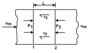
In the turbulent region the friction factor is found to depend on Reynolds number for smooth pipes and both on Reynolds number and roughness for rough pipes. Some empirical equations are given in section and also under discussions on turbulent flow. The value of friction factor with Reynolds number with roughness as parameter is available in Moody diagram. Using the definition of Darcy friction factor and conditions of equilibrium, expression for pressure drop in pipes is derived in this section. Consider an elemental length L in the pipe. The pressures at sections 1 and 2 are P1 and P2.

Fig - 1
The other force involved on the element is the wall shear t0.
Net pressure force in the element is (P1 –P2)
Net shear force in the element is t0 PDL
Force balance for equilibrium yields

From the definition friction factor


Substituting and letting (P1 –P2) to be ΔP.

This reduces to

This equation known as Darcy-Weisbach equation and is generally applicable in most of the pipe flow problems.
Q5) Water flows in a steel pipe (d = 40 mm, k = 0.045x10⁻³ m, µ = 0.001 k/ms) with a rate of 1 lit/s. determine the friction coefficient and the head loss due to friction per meter length of the pipe using: 1- Moody chart? 2- Smooth pipe formula?
A5)
v = Q / A = 0.001 / (π (0.04)2 /4) = 0.796 m/s
Re = ρ v d / µ = (1000x0.796x0.04) / 0.001 = 31840 > 4000
Turbulent flow.
k/d = 0.045x10⁻³ / 0.04 = 0.0011 & Re = 31840 from the chart, f = 0.0065 hf = 4 f L v 2 = 4x0.0065x1x(0.796)2 = 0.0209 m / m of pipe 2 g d 2x9.81x0.04
2. Smooth pipe (Blasius equation):
f = 0.079 / Re 0.25 = 0.079 / (31840) = 0.0059
hf = 4 f L v 2 /2gd
= 4x0.0059x1x(0.796)2/2x9.81x0.04
= 0.02 m / m of pipe
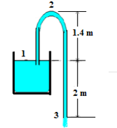
Q6) The pipe of a syphon has 75 mm diameter and discharges water to the atmosphere, as shown in figure. Neglect all possible losses. a. Determine the velocity of flow? b. Find the discharge? c. What is the absolute pressure at the point 2?

Fig - 2
A6)
(a) Applying Bernoulli’s equation between (1) and (3), 2 + 0 + 0 = 0 + 0 + (v 2 3/2g)
v3 = 6.26 m/s
(b) Q = v3 x A = 6.26 x (π (0.075)2 /4) = 0.028 m3 /s
(c) Applying Bernoulli’s equation between (1) and (2),
2 + 0 + 0 = 3.4 + P2/ρg + (6.262 /2g)
P2 = - 3.397 x (1000 x 9.81) = - 33327.8 N/m2 = - 33.33 kPa
P2abs = 64.77 kPa where, (Patm = 98.1 kN/m2 )
Q7) A pipe, 40 m long, is connected to a water tank at one end and flows freely in atmosphere at the other end. The diameter of pipe is 15 cm for first 25 m from the tank, and then the diameter is suddenly enlarged to 30 cm. Height of water in the tank is 8 m above the centre of pipe. Darcy’s coefficient is 0.01. Determine the discharge neglecting minor losses?
A7)

Fig - 3
Loss due to friction, hLf = hf1 + hf2
hf=32fLQ2/ 2 gd5
f = 0.01
Total losses, hT = Q2 ((32 f L1/ 2 gd15)+ (32 f L2 )/ 2 gd2 5 ))
8 = Q2 ((32x0.01) x (25)/(π2g(0.15)5 +(32 x0.01 x15)/ (π2g(0.3)5
Q8) Two reservoirs have 6 m difference in water levels, and are connected by a pipe 60 cm diameter and 3000 m long. Then, the pipe branches into two pipes each 30 cm diameter and 1500 m long. The friction coefficient is 0.01. Neglecting minor losses, determine the flow rates in the pipe system?
A8)
hf = hf1 + hf2
6 = hf1 + hf2
6 = k1 Q12 + k2 Q22
k1 = 32 f1 L1/2gd15= 32*0.01*3000/2×9.81×(0.65)5 = 127.64
k2 = 32 f2 L2/2gd25 = 32*0.01*1500//2×9.81×(0.3)5 = 4084.48
k2 = 32 k1
6 = k1 Q1 2 + 32 k1 Q2 2
hf2 = hf3 & k2 = k3 Q2 = Q3
Q1 = Q2 + Q3 = 2 Q2
6 = k1 Q12 + 8 k1 Q12 = 9 k1 Q1 2 = (9 * 127.64) Q12
= 1148.76 Q12
Q1 = 0.072 m3/s &
Q2 = 0.036 m3/s
Q9) Define friction factor for smooth and rough surface.
A 9) The friction factor or Moody chart is the plot of the relative roughness (e/D) of a pipe against the Reynold's number. The blue lines plot the friction factor for flow in the wholly turbulent region of the chart, while the straight black line plots the friction factor for flow in the wholly laminar region of the chart.
Q10) Describe Moody’s Diagram.
A10)
The Moody chart or Moody diagram is a graph in non-dimensional form that relates the Darcy-Weisbach friction factor, Reynolds number and relative roughness for fully developed flow in a circular pipe. It can be used for working out pressure drop or flow rate down such a pipe.

Pressure drop can then be evaluated as:
 or directly from
Where the density of the fluid is, is the average velocity in the pipe, is the friction factor from the Moody chart, is the length of the pipe and is the pipe diameter.
The Moody chart can be divided into two regimes of flow: laminar and turbulent. For the laminar flow regime, the Darcy–Weisbach friction factor was determined analytically by Poiseuille and is used. In this regime roughness has no discernible effect. For the turbulent flow regime, the relationship between the friction factor and the Reynolds number is more complex and is governed by the Colebrook equation which is implicit in
 turbulent flow.
In 1944, Lewis Ferry Moody plotted the Darcy–Weisbach friction factor into what is now known as the Moody chart.