IC
Unit-4Control Systems Q1) Explain open-loop and close-loop control system. A1): In open loop control system no information on current situation is fed back to element to adjust and maintain the required condition. Consider an example of room heater which have selection switch which allows a 1 kW or a 2 kW heating element to be selected. If a person in room select 1kW switch to heat up the room. If room’s door or window open up then it is impossible to maintain room temperature at required condition. This is an example of open loop control system (Figure 3A) where no information fed back to the element to adjust it and maintain a constant temperature. Now consider a room heater with thermometer to check room temperature regularly and switches the 1kW to 2kW elements on or off, according to difference between actual and required room temperature to maintain it at required level. This is the example of closed loop control system (Figure 3B) in which information is fed back to input system being adjusted according to whether its output is at required level.
A: Open-loop system
B: Closed-loop system Q2) Write a note on basic elements of open-loop and close-loop control system A2): Basic elements of open-loop systemOpen loop system have three basic element (figure 4) discussed as below.Control element: This element determines what action to be taken as a result of the input of the required value signal to the system.Correction element: This element has input from the control element and gives an output of some action designed to change the variable being controlled.Process: This is the process of which a variable is being controlled.
Figure 4: Basic element of control system Basic element of closed-loop systemFunction of each element of closed-loop system (Figure 5) is discuss below Comparison element: The function of this element is to compare required value of variable being controlled with measured value and produces an error signal.Error = measured value – required valueThus if there is a difference between the required value and the measured values of the variable only then there will be an error signal and so required control action is taken. Control unit: This element decides what action are needs to take when receives an error signal. Control plans are used by element to control process e.g. signal which switches on or off when there is an error. Control plan is permanently fixed by the way the elements are connected together known as hard-wired system. Sometimes control plan is programmable systems where the control plan is stored within a memory unit and may be altered by reprogramming it. Correction unit: The correction element takes an action in the process to correct or change the controlled condition. For example: A switch which switches on a heater and so increases the temperature of the process The term actuator is used for the element of a correction unit that provides the power to carry out the control action. Process element: The process is what is being controlled. It could be a room in a house with its temperature being controlled or a tank of water with its level being controlled. Measurement element: This element produces a signal as per required variable condition. For example: a switch which is switched on when a particular position is reached.
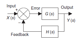
Figure 5: Elements of closed loop system. Q3) Derive the transfer function of feedback control system with 1) Negative feedback2) Positive feedback A3): System with negative feedback.Consider a system with negative feedback loop as shown in figure 8. Where the output Y(s) is fed back via a system with a transfer function H(s) to subtract from the input X(s) to the system having G(s) as transfer function
Figure 8: System with negative feedback.Input for feedback system is Y(s) and output is H(s)Y(s). The error is the difference between the system input signal X(s) and the feedback signal H(s)Y(s)Error= X(s)-H(s)Y(s)
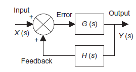
System with positive feedback
Figure 9: System with positive feedback
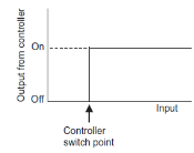
Q4) Explain ON-OFF controller with an exampleA4): ON-OFF controllerON-OFF controller is simplest type of controller. Also known as two position controller. This type of control system is commonly used in domestic system. For example: Heating system, refrigerator etc.ON-OFF controller keep measured value within maximum or minimum value depending upon the controlled variable, whether it is greater or less than the set point.
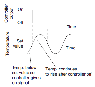
Figure 10: ON-OFF controlConsider a room heating application whose ON-OFF control is shown in figure 11.
Figure 11: Fluctuation of temperature about set value A precise ON-OFF controller will ON when measured value is below set point and controller will be OFF if measured value is above set point. But in actual practice ON-OFF will not work exactly at set point. This is due to transfer or process lag or dead time of instrument. The difference between maximum and minimum level of variable where controller output does not change even ON-OFF is essential is known as dead zone also known as differential gap.ON-OFF control is suitable for following conditionsWhen quick correction actions are need to be take When small and low load change are required When small or no dead zone. Q5) Explain Proportional controllerA5): Proportional control is continuous action operation where output of controller is linear function of error signal i.e. output changes with proportional change of input.Mathematically Where
Where  Controller output
 Error signal
 Gain of controller
 Output of controller when error is zero Constant
  is called proportional sensitivity or gain defined as change manipulated variable cause by unit change in deviation. Mathematically,
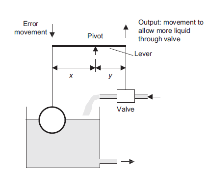
  Controlling the level of water in a cistern using float method is an example of the use of a proportional controller; lever is used to determine the control mode (Figure 12)
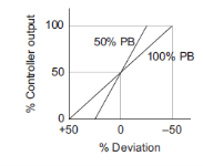
Figure 12: The float-lever proportional controller On controller there is setting for  instead of there is setting for proportional band (PB). Mathematically PB = (1/
 )*100%If PB is high then
  is low i.e. controller is less sensitive or gain decreases causing good control action. On the other hand if PB is low then sensitivity is increases causing output change in large steps.The proportional action is comparatively very fast and control variable settles down close to set point with time. The main drawback of P control method is offset i.e. difference between set point and measured value after measured variable is settles down. And this drawback is permanent feature of proportional control and cannot remove d as it.
Figure 13: Proportional action Q6) write a note on Integral controllerA6): Integral controllerIt is used as reset mode. In integral controller output changes as a rate or speed proportional to magnitude of deviations. Hence larger the deviation faster the correction is applied. If deviation is small then slower the correction is applied.Mathematically Where
Where  Controller output
 Error signal
 Gain of controller
 Integral time If error is not output will begin to increase or decrease till controlled variable reaches exactly to set value. And if error is zero the output stays at value where error is zero. Advantages integral controller
It eliminate offset completely Disadvantages of integral controllerIt keeps oscillating till offset is completely removed. Q7) Write a note on Proportional + integral + derivative control actionA7): For powerful and complex control action PIO control action is used. In PID control action, the output m(t) is a linear combination of Input e(t), the rate of change of input and the time Integral of Input. The control is thus additive information of proportional action, derivative action and integral action. The governing equation of P10 control action is given as,
PID controls are best suited for, Situation which demand very close control that are likely to experience large and sudden fluctuations. PID control is compromise between advantages of PI and PD control offset is eliminated by integral action. Derivative action lowers maximum deviation and elimination of the oscillation occurs in PI control. Derivative action in addition increases the speed of response to set point changes. Q8) Explain Tuning of controller and Explain ultimate tuning method.A8): Tuning While designing of controller involves selecting control modes to be used and control mode setting i.e. selecting which control action P mode, PD mode, PI mode or PID mode choose for particular situation and deciding values of . These determine how the system reacts to a disturbance or a change in the set value, how fast it will respond to changes, how long it will take to settle down after a disturbance or change to the set value, and whether there will be a steady state error.Figure 17 shows types of response that can occur with the different modes of control when subject to a step input (input can be different constant set value or a sudden constant disturbance) P control will give a fast response with oscillations which die away to leave a steady state error. PI control has no steady state error but show more oscillations before settled down. PID control has also no steady state error, because of the integral element, and show fewer oscillations than the PI control. The inclusion of derivative control reduces the oscillations.
Figure 17: Responses to (A) P, (B) PI, and (C) PID controlTuning means methods used to select best controller setting to obtain a particular form of performance, e.g. where an error signal results in the controlled variable oscillating about the required value with an oscillation which decays quite rapidly so that each successive amplitude is a quarter of the preceding one. The following is a description of some of the methods used for tuning. 1) Ultimate Cycle Tuning MethodWith this method, with the closed-loop system, the integral and derivative actions are first reduced to their least effective values. The proportional constant Kp is then set low and gradually increased until oscillations in the controlled variable start to occur. The critical value of the proportional constant Kpc at which this occurs is noted and the periodic time of the oscillations Tc measured. The procedure is thus:1. Set the controller to manual operation and the plant near to its normal operating conditions2. Turn off all control modes but proportional3. Set Kp to a low value, i.e. the proportional band to a wide value4. Switch the controller to automatic mode and then introduce a small set-point change, e.g. 5_10%5. Observe the response6. Set Kp to a slightly higher value, i.e. make the proportional band narrower7. Introduce a small set-point change, e.g. 5_10%8. Observe the response.9. Keep on repeating 6, 7 and 8, until the response shows sustained oscillations which neither grow nordecay. Note the value of Kp giving this condition (Kpu) and the period (Tu) of the oscillation10. The Ziegler and Nichols recommended criteria for controller settings for a system to have quarteramplitude decay are given by Table 1. For a PID system with some overshoot or with no overshoots,the criteria are given by table 2.Table 1: Settings for the Ultimate Cycle Method for Quarter Amplitude Decay
Table 2: Settings for the Ultimate Cycle Method for PI Control
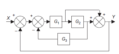
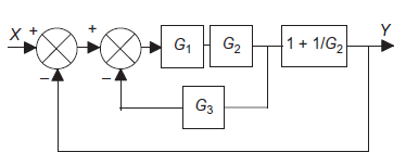
Q9): Use block simplification techniques to simplify the given system
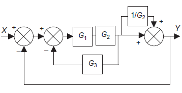
A9): Moving a take-off point
Eliminating a feedforward loop.
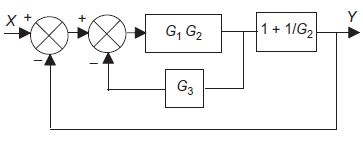
Simplifying series elements
Simplifying a feedback element
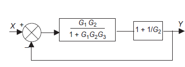
Simplifying series elements
Simplifying negative feedback.
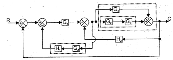
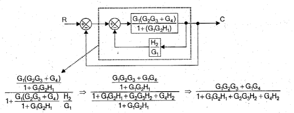
Q10) Use block simplification techniques to simplify the given system
A10):
|
|
|
|
|
This error is input to system G(s) and output is Y(s)
|
|
Error= X(s)+H(s)Y(s) This error is input to system G(s) and output is Y(s)
|
|
|
 Where
Where  Controller output
 Error signal
 Gain of controller
 Output of controller when error is zero Constant
  is called proportional sensitivity or gain defined as change manipulated variable cause by unit change in deviation. Mathematically,
  Controlling the level of water in a cistern using float method is an example of the use of a proportional controller; lever is used to determine the control mode (Figure 12)
|
 instead of there is setting for proportional band (PB). Mathematically PB = (1/
 )*100%If PB is high then
  is low i.e. controller is less sensitive or gain decreases causing good control action. On the other hand if PB is low then sensitivity is increases causing output change in large steps.The proportional action is comparatively very fast and control variable settles down close to set point with time. The main drawback of P control method is offset i.e. difference between set point and measured value after measured variable is settles down. And this drawback is permanent feature of proportional control and cannot remove d as it.
|
 Where
Where  Controller output
 Error signal
 Gain of controller
 Integral time If error is not output will begin to increase or decrease till controlled variable reaches exactly to set value. And if error is zero the output stays at value where error is zero. Advantages integral controller
Substitute d/dt=D and
|
 . These determine how the system reacts to a disturbance or a change in the set value, how fast it will respond to changes, how long it will take to settle down after a disturbance or change to the set value, and whether there will be a steady state error.Figure 17 shows types of response that can occur with the different modes of control when subject to a step input (input can be different constant set value or a sudden constant disturbance) P control will give a fast response with oscillations which die away to leave a steady state error. PI control has no steady state error but show more oscillations before settled down. PID control has also no steady state error, because of the integral element, and show fewer oscillations than the PI control. The inclusion of derivative control reduces the oscillations.
|
Type of controller | Kp | Ti | Td |
P | 0.5Kpu |
|
|
PI | 0.45Kpu | Tu/1.2 |
|
PID | 0.6Kpu | Tu/2 | Tu/8 |
Type of controller | Kp | Ti | Td | |
PID, 1/4 decay | 0.6Kpu | Tu/2 | Tu/8 | |
PID, some overshoot | 0.33Kpu | Tu/2 | Tu/3 | |
PID, no overshoot | 0.2Kpu | Tu/3 | Tu/2 | |
|
|
|
|
|
|
|
|
|
|
|
|
|
|
|
|
0 matching results found


