Unit 3
Friction Devices
Q1. What are the belt drives? Discuss about the velocity ratio, slip and law of belting for the belt drives.
A1.
Belt drives are the drives which are used to transmit power from one shaft to another shaft. these are two types of belt drives flat (rectangular cross- section) and V (trapezoidal cross-section) belts.
Velocity Ratio in Belt Drive
Velocity ration of a belt drive can be defined as the ratio of angular velocity of driven pully to the angular velocity of driving pully. Consider figure 1.
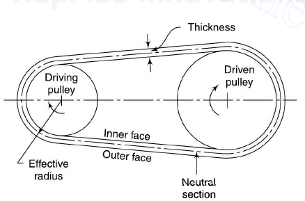
Figure 1 Flat belt drive
Let N1 = rpm of the driving pulley
N2 = rpm of the driven pulley
D1 = diameter of the driving pulley
D2 = diameter of the driving pulley
t = thickness of belt
Assumptions
(i) There is no relative motion between the belt and pulley.
(ii) Belt is inelastic.
Hence, speed of driving pully = speed of driven pulley


If we neglect the thickness of the belt we get,

Slip
Slip in case of the belt drive can be defined as the difference between the velocity of belt and the pully on the driving and driven side. Slip is an undesirable phenomenon which causes reduction in speed of belt on driving shaft which results in decrease in speed of driven shaft.
Let, S1 = slip between the driver and the belt
S2 = percentage slip between the belt and the follower
S = total percentage slip.
Linear speed of belt on driver = 
Linear speed of follower,  =
= 
= 
We know that  and
and 
Substituting, 

Law of Belting
The law of belting states that the center line of the belt as it approaches the pulley must lie in a plane perpendicular to the axis of that pulley, or must lie in the plane of the pulley, otherwise the belt will run off the pulley.
Q2. Discuss about following in brief:
A2.

Where, E = modulus of elasticity of belt material.
b and t are width and thickness of belt.
b. Crowning of pulleys: To prevent the tendency of falling off of the belt from the pulley, face of pulley is provided with a convex curvature, which is known as the crowning of pulley. This phenomenon helps the belt to run in the center of pulley.
c. Compound Belt Drive: Compound belt drive are the drive in which the driven pulley of first pair of drive is mounted on the same shaft on which driver pulley of second pair is mounted. Such an arrangement of compound belt drive is shown in Figure 2. Velocity ration for the compound belt dive is given by following relation.

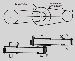
Figure.2. Compound belt drive
Q3. Two pulleys of diameters 450 mm and 150 mm are mounted on two parallel shafts 2 m apart and are connected by a flat belt drive. Find the power which can be transmitted by the belt when the larger pulley rotates at 180 rpm. The maximum permissible tension in the belt is 1 kN, and the coefficient of friction between the belt and the pulley is 0.25. Also find the length of the cross belt required and the angle of arc of contact between the belt and the pulleys.
A3.
Given: Diameter of 1st pulley, d1 = 450 mm, Diameter of 2nd pulley, d2 = 150 mm, distance between the shafts, C = 2 m, Angular speed of larger pulley = 180 rpm, maximum permissible tension in belt T1= 1 kN, coefficient of friction between belt and pulley = 0.25.
To find:
a) Angle of arc of contact between the belt and the pulleys b) Power transmitted by larger pulley
c) Length of cross belt
a) angle of arc of contact for cross belt is given by


b) Power transmitted by a pulley is given by

Where v can be calculated as follows:


Here T1 is given and the value of tension in slack side is calculated as follows:

Substituting the values of , and T1 we get


c) Length of cross belt is given by


Q4. What are clutch? Discuss the types of clutch in brief.
A4: Clutches are the drives which are used to transmit rotary motion between two coincident shafts when desired.
1. Plate Clutch
a. Single plate
b. Multiplate
2. Cone clutch
Single Plate Clutch
A plate clutch consists of a clutch plate attached to a splined hub which slides freely of the driven side in axial direction. Generally, the clutch plate is made of steel having friction lining on each side.
During engagement clutch plate is firmly pressed against the flywheel by the spring-loaded pressure plate. Whereas during disengagement cover attached to the flywheel is pressed by springs and the flywheel and pressure plate rotates with the input shaft. Figure 3 shows the different parts of single plate clutch.
Torque transmitted by such clutches can be calculated using two criteria which are uniform wear and uniform pressure.
Torque transmitted considering the uniform pressure criteria

Torque transmitted considering the uniform wear criteria

![Single Plate Clutch and Multi Plate Clutch [Descriptive Guide]](https://glossaread-contain.s3.ap-south-1.amazonaws.com/epub/1643285428_5320992.jpeg)
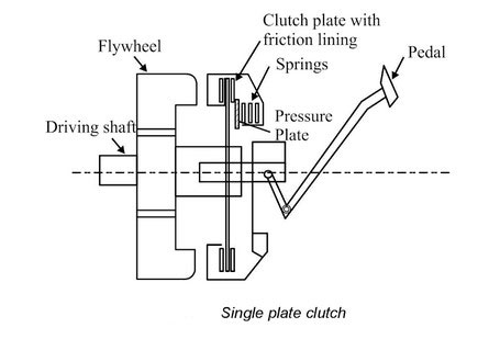
Figure.3. Single plate clutch Figure.4. Multiplate clutch
Multi-Plate Clutch
These kinds of clutches are used at place where limited space is available such as in two wheelers. By increasing the number of plates, the connecting surfaces increase which result in increase in capacity. Figure 4 shows the multiplate clutch.
If n1 be the number of plates on driver shaft and n2 be the number of plates on driven shaft then n will be the number of pairs contact surfaces, which is given by:

The frictional torque T is given by

Where, = coefficient of friction
W = Axial load on the clutch
rm = mean radius of friction surface.
For Uniform pressure criteria

For Uniform wear criteria

Cone Clutch
In case of cone clutch, the contact surfaces are in the shape of cone as shown in figure 5. During engagement the surface A and B are in contact completely due the spring pressure applied on the one cone against all other part of the clutch. While during disengagement the cone B is pulled back with the help of a lever system. In these types of clutches, due to the cone shape the normal force on the contact surface is increases.
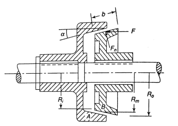
Figure.5. Cone Clutch
In case of cone clutches the frictional torque, T is given by

Where, = coefficient of friction
Fn = Normal force given by

= semi cone angle
Rm = mean radius of friction surface.
Q5. A single-plate clutch, with both sides effective, has inner and outer diameters of friction surface 250 mm and 350 mm, respectively. The maximum intensity of pressure is not to exceed 0.15 MPa. The coefficient of friction is 0.3. Determine the power transmitted by the clutch at a speed of 2400 rpm for (a) uniform wear and (b) uniform pressure.
A5.
Given: inner diameter, di = 250 mm, outer diameter, do = 350 mm, Maximum pressure intensity, pmax = 0.15 Mpa, coefficient of friction = 0.3, Angular speed of clutch, N = 2400 rpm.
To find: Power transmitted for (a) uniform wear and (b) uniform pressure.
Power transmitted by a clutch is given by

T for uniform wear is given by
Where,


b) Uniform pressure


Q6. A plate clutch has three discs on the driving shaft and two discs on the driven shaft, providing four pairs of contact surfaces. The inside and outside diameters of the friction surfaces are 125 mm and 250 mm, respectively. Assuming uniform pressure and coefficient of friction equal to 0.3, find the total spring load pressing the plates together to transmit 30 kW at 1500 rpm.
A6:
Given: number of discs = 3, inner diameter, di = 125 mm, outer diameter, do = 250 mm, coefficient of friction = 0.3, Angular speed = 1500 rpm, power transmitted = 30kW.
To find: Total spring load (W) considering uniform pressure criteria.
We know that, power transmitted by a clutch is given by


And,

For 3 discs n= 4,


Q7. What are brakes? Discuss about shoe brakes and band and block brakes in details.
A7. Brakes are the friction devices which are used to reduces the speed of a moving vehicle or a machine component.
Shoe brakes
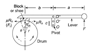
In this kind of brakes there is a shoe which is pressed against the rotating machine pat to reduce its speed or to stop it by applying friction force using lever mechanism. If only one shoe is used for braking, there is a side thrust on the bearing of the shaft supporting the drum. To avoid this side thrust two shoes are used. Brake shoes are generally made of rubber and wood.
Consider figure 6 and it is assumed that the normal reaction and friction forces are being applied at the mid-point of the shoe
Let, r =radius of drum
= coefficient of friction
Rn = normal reaction
F = force applied at the lever
Ff = friction force
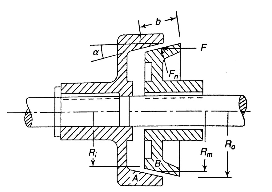
Figure.6. Shoe Brake
Braking torque T = friction force Ff × radius

Rn is obtained by equilibrium condition on the shoe, by taking moment about the point O in Figure 6.


Or

Considering above equation
Case 1: if b= μc, force required to apply brake will be 0 i.e. once the contact between drum and shoe is made the brake will be applied itself. Hence, such brakes are also known as self-locking brakes.
Case 2: as we can see from the equilibrium equation moment of frictional force and the force applied on the lever is in same direction about O, and the friction force is supporting the braking force, hence such brakes are also known as self-energized brakes.
Case 3: if the direction of rotation is reversed the force to be applied on lever will become

Case 4: if pivot lie on the line of action of friction force, c = 0

Here is taken as constant but if the value of > 40° the coefficient of friction is given by

Where outside any trigonometric ratio is to be taken in radians and inside the trigonometric ratio it is to be taken in degrees.
Band and Block Brakes
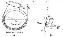 In this kind of brakes number of wooden blocks are held together with the help of flexible steel band. These wooden blocks are pressed against the drum upon application of brake.
Consider figure 7 we can see a diagram of band and block brake in which each block is subtending an angle 2 at the center of drum. Figure 10 shoes the band and block brake (a) and the forces on the block of the brake (b).
Figure.7. Band and block brake
Let us consider
T0 = tension on the slack side of the band
T1 = tension on the tight side of 1st block
Tn = tension on the tight side of the n blocks
= coefficient of friction
Rn = normal reaction on the block
By applying equilibrium


Upon some simplifications we get


So on,

Q8. A bicycle and rider of mass 120 kg are travelling at a speed of 15 km/h on a level road. The rider applies brake to the rear wheel that is 0.9 m in diameter. How far will the bicycle travel before it comes to rest? The force applied on the brake is 100 N and coefficient of friction between the brake and the cycle rim is 0.05. Assume that no other resistance is acting on the bicycle.
A8.
Given: Mass of the bicycle and the rider, m = 120 kg, Speed of the bicycle, v = 15 km/h, diameter of rear wheel = 0.9 m, Force applied on the brakes, R = 100 N, coefficient of friction between brake and rim = 0.05.
To find: the distance travelled by bicycle before stopping.
Friction force can be calculated by


Let ‘s’ be the distance travelled by the bicycle before stopping.
Work done by frictional force before stopping


Kinetic energy possessed by the system,


Upon equating Kinetic energy and Work done
We get,


Q9. A double-shoe brake (Fig. 8) is capable of absorbing a torque of 1500 Nm. The diameter of the brake drum is 300 mm and the angle of contact for each shoe is 90°. The coefficient of friction between the brake drum and the lining is 0.35. Find (a) the spring force necessary to set the brake and (b) width of the brake shoes. The bearing pressure on the lining material is not to exceed 0.25 MPa.
A9. Consider figure 8.
 Given: Torque absorbing capacity, T = 1500 Nm, diameter of brake drum, d = 300 mm, angle of contact of shoe, = 90°, coefficient of friction, = 0.35, maximum bearing pressure allowed = 0.25 MPa.
To find: a) the spring force necessary to set the brake and (b) width of the brake shoes.
a) Let P be the spring force to set the brake. Since the angle of contact is greater than 60°, therefore,
equivalent coefficient of friction


Taking moments about the fulcrum O1, we have


Now taking moments about O2, we have


Let the spring force,

Torque capacity of the brake,


b) Let b be the width of the brake shoes in mm.
Projected bearing area for one shoe,


The normal force is maximum on the left-hand side shoe.


Q10. A band and block brake, with 15 blocks, each of which subtends an angle of 15°, is applied to a drum of 1 m diameter, as shown in Fig.9. The drum and the flywheel mounted on the same shaft has a mass of 1500 kg and a combined radius of gyration of 500 mm. Find (a) maximum braking torque, (b) angular retardation of the drum, and (c) time taken by the system to come to rest from the rated speed of 380 rpm. The coefficient of friction between the drum and the blocks can be taken as 0.25.
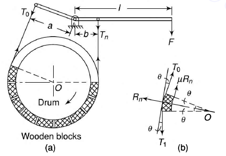
Figure.9. band and block brake
A10.
Given: number of blocks = 15, angle of arc of contact = 15°, diameter of drum = 1 m, mass of drum and flywheel, m = 1500 kg, radius of gyration = 500 mm, Rated speed = 380 rpm.
To find a) maximum braking torque, b) angular retardation of the drum and c) time taken by the system to come to rest.
(a) The braking torque will be maximum when the drum rotates counter-clockwise and the force
P is upwards. Taking moments about O, we have


Braking torque,


b) Let be the angular retardation of the drum


(c) Let t be the time taken to come to rest
Initial angular speed,

Final angular speed,


