Module - 4
Design of Clutches
Q1) Define clutches and basic requirements of clutches.
A1) Mechanism which enables rotary motion of shaft to be transmitted to the second shaft axis, which is coincident with the first. OR
Clutch is a device to connect driving and driven shafts of a machine, where the driven shaft can be disconnected almost instantaneously from the driving shaft as desired by the operator or driver.
Requirements of clutch:
1. Torque Transmission
2. Gradual Engagement: Clutch should take the drive gradually without occurrence of sudden jerks.
3. Heat Dissipation: During clutch application large amount of heat is generated, the rubbing surfaces should have sufficient area and mass to absorb the heat generated. The design of clutch should ensure proper ventilation or cooling for adequate dissipation of heat.
Q2) Explain friction clutch and its working principle.
A2) The friction clutches work on the fact that friction is caused when two rotating discs come into contact with each other.
Principle for friction clutches:

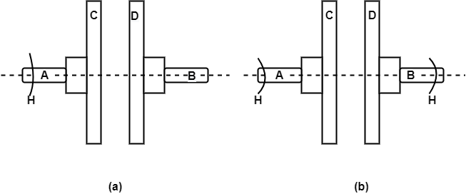
Figure: Principle for friction clutch
Let the shaft A and Disc C be revolving at some speed say N rpm. Shaft B and disc D keyed to it are stationary, initially when the clutch is not engaged.
Now apply some axial force W to disc D, so that it comes in contact with Disc C. As soon as the contact is made the force of friction between C and D will come into play and consequently the disc D will also start revolving.
The speed of D depends upon friction force present, which in turn is proportional to the force W applied.
If W is increased gradually, the speed of D will be increased correspondingly till the stage comes when speed of D becomes equal to speed of C.
Then clutch is said to be fully engaged.
Let W = axial load applied. µ= coefficient of friction R= effective mean radius of friction surface. Then, T = W R
Q3) Elaborate the centrifugal clutch with diagram.
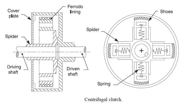
A3) In fully centrifugal type clutches, the springs are eliminated altogether and only centrifugal force is used to apply the required pressure for keeping the clutch in engaged position.
The centrifugal clutches are usually incorporated into the motor pulleys. It consists of a number of shoes on the inside of a rim of the pulley, as shown in Fig. The outer surface of the shoes is covered with a friction material. These shoes, which can move radially in guides, are held against the boss (or spider) on the driving shaft by means of springs. The springs exert a radially inward force which is assumed constant. The mass of the shoe, when revolving, causes it to exert a radially outward force (i.e. centrifugal force). The magnitude of this centrifugal force depends upon the speed at which the shoe is revolving. A little consideration will show that when the centrifugal force is less than the spring force, the shoe remains in the same position as when the driving shaft was stationary, but when the centrifugal force is equal to the spring force, the shoe is just floating. When the centrifugal force exceeds the spring force, the shoe moves outward and comes into contact with the driven member and presses against it. The force with which the shoe presses against the driven member is the difference of the centrifugal force and the spring force. The increase of speed causes the shoe to press harder and enables more torque to be transmitted.

Q4) Define internal expansion elements with diagram.
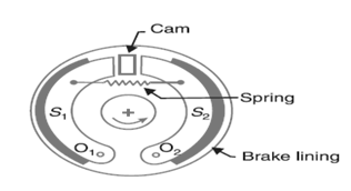
A4) An internal expanding brake consists of two shoes S] and S2 as shown in Fig. The outer surface of the shoes are lined with some friction material (usually with Ferodo) to increase the coefficient of friction and to prevent wearing away of the metal.
Each shoe is pivoted at one end about a fixed fulcrum O1 and O2 and made to contact a cam at the other end. When the cam rotates, the shoes are pushed outwards against the rim of the drum. The friction between the shoes and the drum produces the braking torque and hence reduces the speed of the drum.

Figure: Inner Expanding Brake
Q5) Discuss the assumptions for clutch and brake designing.
A5) The following assumptions are implied by the preceding analysis:
Q6) What is an external contraction element explain with figure?
A6) External expanding brakes contract to make contact with the rotating drum.
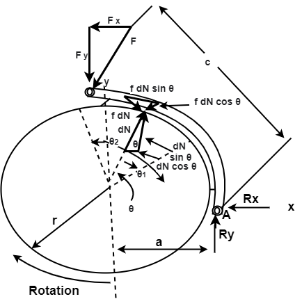
The notation for external contracting shoes is shown in Fig.

The moments of the frictional and normal forces about the hinge pin are the same as for the internal expanding shoes.
Q7) Derive the expression for the external contraction elements for braking.
A7)
External expanding brakes contract to make contact with the rotating drum.
The notation for external contracting shoes is shown in Fig.


Both these equations give positive values for clockwise moments (Fig 16-11) when used for external contracting shoes. The actuating force must be large enough to balance both moments

The horizontal and vertical reactions at the hinge pin are found in the same manner as for internal expanding shoes. They are


By using Eq.(16-8) and Eq. (c) from Sec. 16-2, we have


If the rotation is counter clockwise, the sign of the frictional term in each equation is reversed. Thus Eq. (16-11) for the actuating force becomes

And self-energization exists for counterclockwise rotation. The horizontal and vertical reactions are found, in the same manner as before, to be


When external contracting designs are used as clutches, the effect of centrifugal force is to decrease the normal force.
Thus, as the speed increases, a larger value of the actuating force F is required.
Q8) What is the band type brake? Explain.
A8) A band brake is a primary or secondary brake, consisting of a band of friction materials that tightens concentrically around a cylindrical piece of equipment either to prevent it from rotating or to slow it.
A band brake consists of a flexible band of leather, one or more ropes, or a steel lined with a friction material, which embraces a part of a circumference of the drum. It is also termed as simple band brake.
In this one end of the band is attached to a fulcrum of the lever while the other end is attached to the lever at the distance b.
When the force P is applied to the lever C, the lever turns about the fulcrum O and tightens the bands and hence the brakes are applied. Band is the wrapped part round a rotating drum.
Q9) Explain the classifications of brake.
A9) A Brake is device by means of which artificial frictional resistance is applied to a moving machine member, in order retard or stop the motion of a machine. In the process of performing this function, the brake absorbs either kinetic energy of the moving member or potential energy given up by objects being lowered by hoists, elevators etc. The energy absorbed by brakes is dissipated in the form of heat. This heat is dissipated in the surrounding air (or water which is circulated through the passages in the brake drum) so that excessive heating of the brake lining does not take place. The Capacity of brake depends upon the following factors:
CLASSIFICATION
Air brakes are used in trucks, buses, trailers, and semi-trailers. George Westinghouse first developed air brakes for use in railway service. He patented a safer air brake on March 5, 1872.
Hydraulic brakes: The hydraulic brake is an arrangement of braking mechanism which uses brake fluid, typically containing ethylene glycol, to transfer pressure from the controlling unit. In 1918 Malcolm Lougheed developed a hydraulic brake system.
Electrical brakes: Electric brakes are used in electrically driven utilities and machines in industries and mainly in electric automotive such as electric locos. This was designed as an alternative to the conventional braking system of applying friction over the wheels to slow them.
Mechanical brakes: In mechanical brake friction force is applied by giving pressure on the surface of drum or disk. It may further divide axial brake and radial brake as per the direction of force acting on drum. Radial break may internal or external.

 Disc brakes: A brake disc is usually made of cast iron, reinforced carbon-carbon or ceramic matrix composites. This is connected to the wheel and/or the axle. To stop the wheel, friction material in the form of brake pads (mounted on a device called a brake caliper) is forced mechanically, hydraulically, pneumatically or electromagnetically against both sides of the disc.

Figure: Short and long shoe brake
Q10) Explain the construction of band brake.
A10) Construction of band brake:
Brake band is made of a rope or belt band which is lined with a friction material.
Band is wrapped partially around a drum with its free ends to a lever. An external force can be applied to the free ends of this lever for braking.
Due to the external forces, there is a friction between the bands. Due to this friction force, the band is tightening and a tangential force acts on the drum.
This tightness in the band will create the tension in the band, as a result it stops the wheel connected.

Let T1= Tension in the tight side of the band
T2= Tension in the slack side of the band
Θ= Angle of lap, µ= coefficient of friction between the band and the drum.
r= radius of the drum
t= thickness of the band
re= effective radius of the drum=r+t/2