Unit- 2
Turning Moment Diagram
Question:1. Determine the expression of Maximum Fluctuation of energy.
A1: Expression for maximum fluctuation of energy
Let  = maximum speed during the cycle.
 = minimum speed during the cycle.
N = mean speed of flywheel =
And  = co-efficient of fluctuation of speed
The mean kinetic energy of the flywheel


Question:2. Derive the expression for Energy Stored in a fly wheel.
A2:
A flywheel is shown in Fig. We have discussed in that when a flywheel absorbs energy, its speed increases and when it gives up energy, its speed decreases.
Let, m = Mass of the flywheel in kg,
k = Radius of gyration of the flywheel in meters
I = Mass moment of inertia of the flywheel about its axis of rotation in kg

 maximum and minimum speeds during the cycle in r.p.m
N =mean speed during the cycle in r.p.m = 
 = mean angular speed during the cycle in r.p.m =
 coefficient of fluctuation of speed =
We know that the mean kinetic energy of the fly wheel.

As the speed of the fly wheel changes from ω1 to ω2 the maximum fluctuation of energy.
 = maximum K.E – minimum K.E

 -------1


 (in N- m or joules)
Question:3. Derive the expression for dimension of flywheel.
A3:
Expression for Dimensions of Flywheel:
D= mean diameter of rim.
R= mean radius of rim.
A= cross- sectional area of rim.
 = density of rim material
N = speed of flywheel
 Angular velocity of flywheel.
 Tensile (or hoop) stress due to centrifugal force, and
V= linear velocity at the mean radius.

2. Consider a small element of rim which subtends an angle  at the centre of the flywheel.
3. Volume of the small element and, mass of the small element = AR 
Dm=Density ×volume
=
4. Centrifugal force that acts radially outwards

=
5. Vertical component of dF= dF sin 
= 
6. Total vertical upward force tending to burst the rim across the diameter XY,
 ………1
………1
7. This vertical upward force will produce hoop stress (or centrifugal stress or circumferential stress) and it is resisted by 2p, such that
 …………….2
8. On equating eq. (1) and eq. (2)


the mass of rim, m= volume × density
=

Using equations (1) and (2), we can find the value of the mass radius and cross- sectional area of the rim.
If the cross- sectional area of the rim is rectangular then,
 , where

 Thickness of the rim
Question:4. The mass of flywheel of an engine is 6.5 tonnes and the radius of gyration is 1.8 metres. It is found from the turning moment diagram that the fluctuation of energy is 56 kN-m. If the mean speed of the engine is 120 r.p.m., find the maximum and minimum speeds.
A4: Given: m = 6.5 t = 6500 kg ; k = 1.8 m ;
 = 56 kN-m = 56 ×
  N-m; N = 120 r.p.m.
Let  and
and  = Maximum and minimum speeds respectively

= 27 715 ( )
)
But,  = 56 ×
  /27 715 = 2 r.p.m. …………….(i)
that mean speed (N),
 ……………..(ii)
From equations (i) and (ii)
 = 121 r.p.m., and
 = 119 r.p.m. ……………….Ans.
Question:5. A horizontal cross compound steam engine develops 300 kW at 90 r.p.m. The coefficient of fluctuation of energy as found from the turning moment diagram is to be 0.1 and the fluctuation of speed is to be kept within ± 0.5% of the mean speed. Find the weight of the flywheel required, if the radius of gyration is 2 metres.
A5:
Given: P = 300 kW = 300 ×  W; N = 90 r.p.m.;
  = 0.1; k = 2 m
We know that the mean angular speed, = 2
= 2  N/60 = 2
  × 90/60 = 9.426 rad/s
Let  = Maximum and minimum speeds respectively.
Since the fluctuation of speed is ± 0.5% of mean speed, therefore total fluctuation of speed, = 1%
= 1% = 0.01
and coefficient of fluctuation of speed,
Cs = w1-w2/w =0.01
We know that work done per cycle
= P × 60 / N = 300 ×  × 60 / 90 = 200 ×
  N-m
N-m
Maximum fluctuation of energy,
∆ E = Work done per cycle x CE = 200 x 10 3 x 0.1 = 20 x 10 3 N-m
Let m = Mass of the flywheel.
maximum fluctuation of energy ( E),
E),
20 x 10 3 = m.k2 . w2. Cs = m x 2 2 x (9.426) 2 x 0.01 = 3.554m
m =20 ×  /3.554 = 5630 kg …………..Ans.
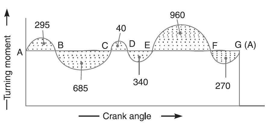
Question:6. The turning moment diagram for a petrol engine is drawn to the following scales: Turning moment, 1 mm = 5 N-m; crank angle, 1 mm = 1°. The turning moment diagram repeats itself at every half revolution of the engine and the areas above and below the mean turning moment line taken in order are 295, 685, 40, 340, 960, 270  . The rotating parts are equivalent to a mass of 36 kg at a radius of gyration of 150 mm. Determine the coefficient of fluctuation of speed when the engine runs at 1800 r.p.m.
A6:
Given: m = 36 kg; k = 150 mm = 0.15 m; N = 1800 r.p.m. or
= 2  × 1800/60 = 188.52 rad /s

Fig.1.1 Turning moment diagram for a petrol engine
Since the turning moment scale is 1 mm = 5 N-m and
crank angle scale is 1 mm = 1° =  /180 rad,
1  on turning moment diagram,

Let the total energy at A = E, therefore
Energy at B = E + 295 ... (Maximum energy)
Energy at C = E + 295 – 685 = E – 390
Energy at D = E – 390 + 40 = E – 350
Energy at E = E – 350 – 340 = E – 690 ...(Minimum energy)
Energy at F = E – 690 + 960 = E + 270
Energy at G = E + 270 – 270 = E = Energy at A
maximum fluctuation of energy,
 E = Maximum energy – Minimum energy
= (E + 295) – (E – 690) = 985 
=985 x π/36 = 86 N-m = 86J
Let  = Coefficient of fluctuation of speed.
Maximum fluctuation of energy ( E)
E)
86 = m. k2 w2 .Cs = 36 x (0.15)2 x(188.52) 2 CS = 28787 CS
 = 86 / 28 787 = 0.003 or 0.3% …………Ans.
Question:7. Define the maximum fluctuation of speed, the coefficient of fluctuation of speed with proper expression.
A7:
The fluctuation of speed can be defined as the variation in speeds of device or object (crank shaft) during a cycle and the difference between the maximum and minimum speeds during a cycle is called the maximum fluctuation of speed.
The difference between the maximum and minimum speeds during a cycle is called the maximum fluctuation of speed. The ratio of the maximum fluctuation of speed to the mean speed is called the coefficient of fluctuation of speed.
Let  = Maximum and minimum speeds in r.p.m. during the cycle, and
N =mean speed in r.p.m. = 
Coefficient of fluctuation of speed.

(
 (in terms of linear speeds)
Question:8. Describe the Turning Moment Diagram for a Four Stroke IC Engine.
A8: A turning moment diagram for a four-stroke cycle internal combustion engine is shown in Fig. We know that in a four-stroke cycle internal combustion engine, there is one working stroke after the crank has turned through two revolutions, i.e. 720° (or 4 π radians).

Fig.1.2: Turning moment diagram for a four-stroke cycle internal combustion engine
Since the pressure inside the engine cylinder is less than the atmospheric pressure during the suction stroke, therefore a negative loop is formed as shown in Fig. During the compression stroke, the work is done on the gases, therefore a higher negative loop is obtained. During the expansion or working stroke, the fuel burns and the gases expands, therefore a large positive loop is obtained. In this stroke, the work is done by the gases. During exhaust stroke, the work is done on the gas, therefore a negative loop is formed. It may be noted that the effect of the inertia forces on the piston is taken into account in Fig.
Question:9. Describe Turning Moment Diagram for a Single Cylinder Double Acting Steam Engine.
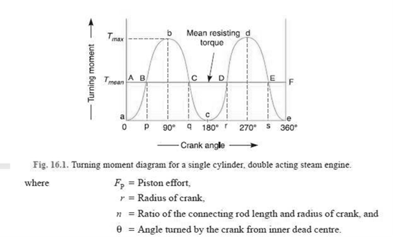
A9: A turning moment diagram for a single cylinder double acting steam engine is shown in Fig. 16.1. The vertical ordinate represents the turning moment and the horizontal ordinate represents the crank angle.
We know that the turning moment on the crankshaft is written as:


From the above expression, we see that the turning moment (T) is zero, when the crank angle (θ) is zero.
The turning moment in crank shaft is maximum when the crank angle is 90° and it is again zero when crank angle is 180°.
This is shown by the curve abc in Fig. given above and it represents the turning moment diagram for outstroke. The curve cde is the turning moment diagram for in stroke and is somewhat similar to the curve abc.
Since the work done is the product of the turning moment and the angle turned, therefore the area of the turning moment diagram represents the work done per revolution. In actual practice, the engine is assumed to work against the mean resisting torque, as shown by a horizontal line AF. The height of the ordinate a A represents the mean height of the turning moment diagram. Since it is assumed that the work done by the turning moment per revolution is equal to the work done against the mean resisting torque, therefore the area of the rectangle aAFe is proportional to the work done against the mean resisting torque.
Question:10. Define
A10:
CE = Maximum fluctuation of energy / Work done per cycle.