Unit-5
Effects of inertia of reciprocating masses on engine frame:
Question1.: Explain the effect of inertia of reciprocating mass on engine frame.
A1:

Fig.5.1. Reciprocating engine mechanism
Let FR = Force required to accelerate the reciprocating parts
Fi= Inertia force due to reciprocating parts
FB = Force acting on the crankshaft bearing or main bearing.
Since FR and FI are equal in magnitude but opposite in direction they balance each other. The horizontal component of FB acting along the line of reciprocation is also equal and opposite to FI. This force FBH = FV is an unbalanced force or shaking force and required to be properly balanced.
Question 02: Derive the Unbalanced primary and secondary forces and couples.
A2: Let, m = Mass of the reciprocating parts,
l = Length of the connecting rod PC,
r = Radius of the crank OC,
θ = Angle of inclination of the crank with the line of stroke PO,
ω = Angular speed of the crank,
n = Ratio of length of the connecting rod to the crank radius = l / r.
The acceleration of the reciprocating parts is-
aR = w 2 . r ( cos  + cos 2
 /n)
/n)
 m. w 2 . r ( cos
  + cos 2
 /n)
/n)
The horizontal component of the force exerted on the crank shaft bearing (i.e.,  ) is equal and opposite to inertia force (
 ). This force is an unbalanced one and is denoted by
  .
.
Unbalanced force,
Fv = m. w 2 . r ( cos  + cos 2
 / n) = m. w2 . r cos
  + m . w 2 . r x cos 2
 /n = Fp + Fs
= (m . w 2 . r cos  ) is known as primary unbalanced force and
( m . w 2 . r cos  /n) is called secondary unbalanced force.
Question 03: Define In-line engine and conditions that must be satisfied in order to give the primary balance of the reciprocating parts of a multi-cylinder engine.
A3: In-line engines:
The multi-cylinder engines with the cylinder centre lines in the same plane and on the same side of the centre line of the crankshaft, are known as In-line engines.
The following two conditions must be satisfied in order to give the primary balance of the reciprocating parts of a multi-cylinder engine:
1. The algebraic sum of the primary forces must be equal to zero. In other words, the primary force polygon must close.
2. The algebraic sum of the couples about any point in the plane of the primary forces must be equal to zero. In other words, the primary couple polygon must close.
Question 04: Describe the Balancing of Secondary Forces of Multi-cylinder In-line Engines.
A4:
When the connecting rod is not too long (i.e., when the obliquity of the connecting rod is considered), then the secondary disturbing force due to the reciprocating mass arises. The secondary force,

i.e.,


Fig.5.2. Balancing of Secondary Forces of Multi-cylinder In-line Engines.
In multi-cylinder in-line engines, each imaginary secondary crank with a mass attached to the crankpin is inclined to the line of stroke at twice the angle of the actual crank. The values of the secondary forces and couples may be obtained by considering the revolving mass.
The following two conditions must be satisfied in order to give a complete secondary balance of an engine:
1. The algebraic sum of the secondary forces must be equal to zero. In other words, the secondary force polygon must close.
2. The algebraic sum of the couples about any point in the plane of the secondary forces must be equal to zero. In other words, the secondary couple polygon must close.
Question 05: A single cylinder reciprocating engine has speed 240 rpm, stroke 300 mm, mass of reciprocating parts 50 kg, mass of revolving parts at 150 mm radius 30 kg. If all the mass of revolving parts and two-third of the mass of reciprocating parts are to be balanced, find the balance mass required at radius of 400 mm and the residual unbalanced force when the crank has rotated 60 from IDC.
A5:
N = 240 rpm
L = 300mm
m=50kg
mp = 30kg
r = ½ = 150mm
w = 2 π N /60 = 2 π x 240/60 = 25.13 rad/sec
(i) Mass to be balanced at crank pin = cm + mp = 2/3 x 50 + 30 = 63.33 Kg
mc rc = mr
mc x 400 = 63.33 x 150
mc = 23.75 kg
(ii) Unbalanced force at 
= √[(1-c) mrw 2 cos  ] 2 + [cm rw 2 sin
  ] 2
] 2
= √(1-2/3) x 50 x 0.15 x (25.13) 2 cos 60 ] 2 + [ 2/3 x 50 x 0.15 x (25.13) 2 sin 60] 2
= √ (789.36) 2 + (2734.55) 2
= 2846.2 N
Question 06: Explain the types of locomotive in detail.
A6: Locomotives are of two types, coupled and uncoupled. If two or more pairs of wheels are coupled together to increase the adhesive force between the wheels and the track, it is called a coupled locomotive. Otherwise, it is an uncoupled locomotive.
Locomotives usually have two cylinders. If the cylinders are mounted between the wheels, it is called an inside cylinder locomotive and if the cylinders are outside the wheels, it is an outside cylinder locomotive. The cranks of the two cylinders are set at 90° to each other so that the engine can be started easily after stopping in any position. Balance masses are placed on the wheels in both types.
In coupled locomotives, wheels are coupled by connecting their crankpins with coupling rods. As the coupling rod revolves with the crankpin, its proportionate mass can be considered as a revolving mass which can be completely balanced.
Thus, whereas in uncoupled locomotives, there are four planes for consideration, two of the cylinders and two of the driving wheels, in coupled locomotives there are six planes, two of cylinders, two of coupling rods and two of the wheels. The planes which contain the coupling rod masses lie outside the planes that contain the balance (counter) masses. Also, in case of coupled locomotives, the mass required to balance the reciprocating parts is distributed among all the wheels which are coupled. This results in a reduced hammer blow.
Question 07: Explain the Balancing of Primary force and couple forces.
A7: Balancing of Primary force and couple:
The multi-cylinder engines with the cylinder centre lines in the same plane and on the same side of the centre line of the crankshaft are known as In-line engines.
The following two conditions must be satisfied in order to give the primary balance of the reciprocating parts of a multi-cylinder engine:
The algebraic sum of the primary forces must be equal to zero. In other words, the primary force polygon must close and
Primary force, FPF =  r w 2 cos
The algebraic sum of the couples about any point in the plane of the primary forces must be equal to zero. In other words, primary couple polygon must close.
Primary couple , FPC =  r l w 2 cos
The primary unbalanced force due to the reciprocating masses is equal to the component, parallel to the line of stroke, of the centrifugal force produced by the equal mass placed at the crankpin and revolving with it. Therefore, in order to give the primary balance of the reciprocating parts of a multi-cylinder engine, it is convenient to imagine the reciprocating masses to be transferred to their respective crankpins and to treat the problem as one of revolving masses.
Question 08: Explain the following term
A8:
1.Balancing of Rotating Masses
Whenever a certain mass is attached to a rotating shaft, it exerts some centrifugal force, whose effect is to bend the shaft and to produce vibrations in it. In order to prevent the effect of centrifugal force, another mass is attached to the opposite side of the shaft, at such a position so as to balance the effect of the centrifugal force of the first mass. This is done in such a way that the centrifugal forces of both the masses are made to be equal and opposite. The process of providing the second mass in order to counteract the effect of the centrifugal force of the first mass is called balancing of rotating masses.
2.Balancing Machines
A balancing machine is able to indicate whether a part is in balance or not and if it is not, then it measures the unbalance by indicating its magnitude and location.
Question 09: A two-cylinder locomotive has the following specifications; Reciprocating mass per cylinder = 306 Kg
Crank radius = 300 mm Angle between cranks = 90°
Driving wheels diameter = 1800 mm Distance between cylinder centers = 650 mm
Distance between driving wheel planes = 1550 mm
Determine (a) The fraction of reciprocating masses to be balanced, if the hammer blow is not to exceed 46 KN at 96.5 Km/hr.
(b) The variation in tractive force.
(c) The maximum swaying couples.
A9: Given-
m = 300 kg D = 1.8 m or R= 0.9 m
r = 0.3 m Hammer blow = 46 kN
v = 96.5 km/h = 26.8 m/s
The mass of the reciprocating parts to be balanced = c.m = 300c kg
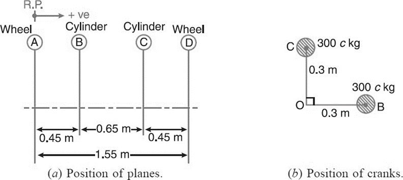

Fig.5.3. Table
Now the couple polygon, to some suitable scale, may be drawn with the data given in Table 5.3. (column 7), as shown in Fig. 5.3. The
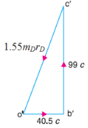 closing side of the polygon (vector c′o′) represents the balancing couple and is proportional to 1.55 B.b.
From the couple polygon,
1.55 mD rD = √(40.5c) 2 + (99c) 2 = 107 c
mD rD= 69 c
Angular speed w = v/R
= 26.8/0.9 =29.8 rad/s
Hammer blow = mD rD w 2
46000 = 69c(29.8) 2
c = 0.751
Variation tractive effort =  √2(1-c) mr w2
= √2 (1-0.751) x 300 x0.3 x(29.8) 2
= 28140 N
Swaying couple  1/√2 (1-c) m r w2
=1/√2 (1-0.751) x 300 x0.3 x(29.8) 2 x 0.65 = 9148 Nm
Question 10: A four crank engine has the two outer cranks set at 120° to each other, and their reciprocating masses are each 400 kg. The distance between the planes of rotation of adjacent cranks are 450 mm, 750 mm and 600 mm. If the engine is to be in complete primary balance, find the reciprocating mass and the relative angular position for each of the inner cranks. If the length of each crank is 300 mm, the length of each connecting rod is 1.2 m and the speed of rotation is 240 r.p.m., what is the maximum secondary unbalanced force?
A10:
m1 = m4 = 400kg N = 240 rpm r = 300mm = 0.3 m
w = 2 π N / 60 = 2 π x 240/60= 25.14 rad/s
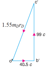


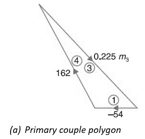
Fig.5.4. primary couple polygon
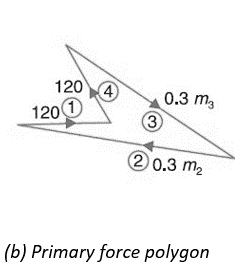
Since the engine is to be in complete primary balance, therefore the primary couple polygon and the primary force polygon must close. First of all, the primary couple polygon, as shown in Fig.5.4. (a), is drawn to some suitable scale from the data given in in order to find the reciprocating mass for crank 3. Now by measurement, we find that 0.225 m3= 196 kg-m2; m3 = 871 kg.
and its angular position with respect to crank 1 in the anticlockwise direction,
θ3= 326°.
Now in order to find the reciprocating mass for crank 2, draw the primary force polygon, as shown in Fig. (b), to some suitable scale from the data given in Tab. Now by measurement, we find that 0.3 m2 = 284 kg-m
m2 = 947 kg.
and its angular position with respect to crank 1 in the anticlockwise direction,
θ2 = 168
(a) Secondary crank positions (b) Secondary force polygon
Fig.5.5. secondary crank positions
The secondary crank positions obtained by rotating the primary cranks at twice the angle, is shown in Fig.(a). Now draw the secondary force polygon, as shown in Fig.(b), to some suitable scale, from the data given in Table (column 6). The closing side of the polygon shown dotted in Fig. (b) represents the maximum secondary unbalanced force. By measurement, we find that the maximum secondary unbalanced force is proportional to582 kg-m.
∴ Maximum Unbalanced Secondary Force,
U.S.F. = 582 * 
USF = 582 x (25.14) 2/ 1.2 /0.3
USF = 91960 N