Tooling for conventional and non-conventional machining processes
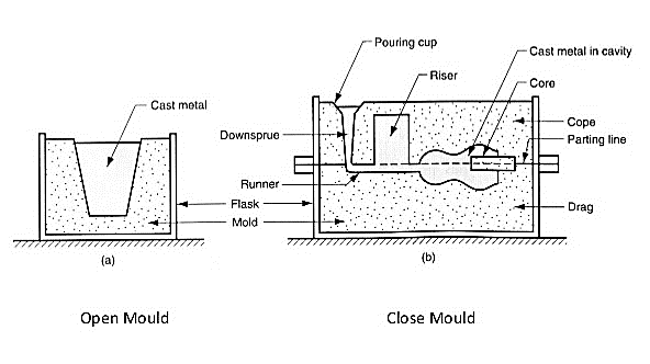
Q1) What do you mean by mould. Write its types?
A1)
Types of moulding:

Q2) What are cutting tool materials. Name them.
A2)
Cutting-Tool Materials:
• Tool bits generally made of seven materials: -
1) Molybdenum-base (Group M)
2) Tungsten-base (Group T)
2. Cast alloys (such as stellite):
1) High hardness
2) High resistance to wear
3) Excellent red-hardness
3. Cemented carbides
4. Ceramics
5. Cermets
6. Cubic Boron Nitride
7. Polycrystalline Diamond
Q3) What do you mean by jig and fixtures. Write its uses.
A3)
Jigs and Fixtures:
Uses of Jigs and Fixtures:
There use partially automates the machine tool.
Q4) What is the purpose of using jigs and fixture?
A4)
Purpose of Using Fixtures and Jigs
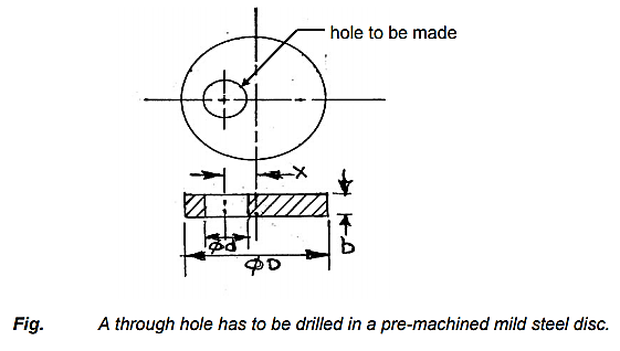
Either adjusting the vise position w.r.t. the fixed drill axis.
Or moving the drilling machine table and then locking the table position.
Or moving the radial arm and the drilling head, if it is a radial drilling machine.

Fig. A through hole has to be drilled in a pre-machined mild steel disc
- To eliminate marking, punching, positioning, alignments etc.
- Easy, quick and consistently accurate locating, supporting and clamping the blank in alignment of the cutting tool
- Guidance to the cutting tool like drill, reamer etc.
- Increase in productivity and maintain product quality consistently
- To reduce operator’s labor and skill – requirement
- To reduce measurement and its cost
- Enhancing technological capacity of the machine tools
- Reduction of overall machining cost and also increase in interchangeability.
Q5) What is the design consideration of Jigs?
A5)
Design of Jigs:
Design Consideration in Jigs:
(a) The main frame of jig must be strong enough so that the deflection of jig is as minimum as possible. This deflection of jig is caused due to the forces of cutting, clamping of the workpiece or clamping to the machine table. The mainframe of the jig should have the mass to prevent vibration and chatter.
(b) Frames should be built from simple sections so that frames can be fastened with screws or welded, whenever necessary. Those parts of the frame that remain intact with the jig may be welded. The parts needing frequent changing may be held with the screws. Where the body of jig or fixture has complex shape, it may be cast from good grade of cast iron.
(c) Clamping should be fast enough and require least amount of effort.
(d) Clamps should be arranged so that they are readily available and may be easily removed.
(e) Clamps should be supported with springs so that clamps are held against the bolt head wherever possible.
(f) If the clamp is to swing off the work, it should be permitted to swing as far as it is necessary for removal of the workpiece.
(g) All locators, clamps should be easily visible to the operator and easily accessible for cleaning, positioning or tightening.
(h) Provision should be made for easy disposal of chip so that storage of chips doesn’t interfere with the operation and that their removal during the operation doesn’t interfere with the cutting process.
(i) All clamps and support points that need to be adjusted with a wrench should be of same size. All clamps and adjustable support points should be capable of being operated from the fronts of the jig.
(j) Workpiece should be stable when it is placed in jig. If the workpiece is rough, three fixed support points should be used. If workpiece is smooth, more than three fixed support points may be used. Support point should be placed as farthest as possible from each other.
(k) The three support points should circumscribe the center of gravity of the workpiece.
(l) The surface area of contact of support should be as small as possible without causing damage to the workpiece. This damage is due to the clamping or work forces.
(m) Support points and other parts are designed in such a way that they can be easily replaced on failure.
Q6) What is the design consideration in fixtures?
A6)
Fixture
Design Consideration in Fixtures
(a) The main frame of fixture must be strong enough so that deflection of the fixture is as minimum as possible. This deflection of fixture is caused because of forces of cutting, clamping of the workpiece or clamping to the machine table. The main frame of the fixture should have the mass to prevent vibration and chatter.
(b) Frames may be built from simple sections so that frames may be fastened with screws or welded whenever necessary. Those parts of the frame that remain permanently with the fixture may be welded. Those parts that need frequent changing may be held with the screws. In the situation, where the body of fixture has complex shape, it may be cast from good grade of cast iron.
(c) Clamping should be fast enough and require least amount of effort.
(d) Clamps should be arranged so that they are readily available and may be easily removed.
(e) Clamps should be supported with springs so that clamps are held against the bolt head wherever possible.
(f) If the clamp is to swing off the work, it should be permitted to swing as far as it is necessary for removal of the workpiece.
(g) All locator’s clamps should be easily visible to the operator and easily accessible for cleaning, positioning or tightening.
(h) Provision should be made for easy disposal of chip so that storage of chips doesn’t interfere with the operation and that their removal during the operation doesn’t interfere with the cutting process.
(i) All clamps and support points that need to be adjusted with a wrench should be of same size. All clamps and adjustable support points should be capable of being operated from the fronts of the fixture.
(j) Workpiece should be stable when it is placed in fixture. If the workpiece is rough, three fixed support points should be used. If workpiece is smooth, more than three fixed support points may be used. Support point should be placed as farthest as possible from each other.
(k) The three support points should circumscribe the center of gravity of the workpiece.
(l) The surface area of contact of support should be as small as possible without causing damage to the workpiece. This damage is due to the clamping or work forces.
(m) Support points and other parts are designed in such a way that they may be easily replaced if they break.
Q7) Write various types of vise fixtures and its applications.
A7)
Types of Fixtures and Its Industrial Applications:
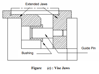
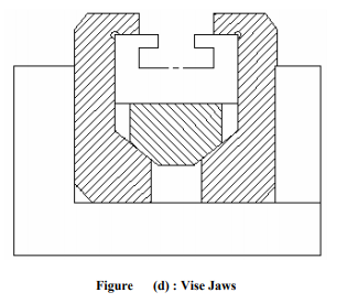
Vise Fixture


Q8) What do you mean by press working and write its features?
A8)
Q9) What do you mean by punch design?
A9)
Punch Design

Q10) What do you understand by Die forging and write its types?
A10)
Die Forging is a manufacturing process involving the shaping of metal using localized compressive forces. Forging is often classified according to the temperature at which it is performed: "cold", "warm", or "hot" forging. Forged parts can range in weight from less than a kilogram to 580 metric tons. Forged parts usually require further processing to achieve a finished part.
Forging can produce a piece that is stronger than an equivalent cast or machined part. As the metal is shaped during the forging process, its internal grain deforms to follow the general shape of the part. As a result, the grain is continuous throughout the part, giving rise to a piece with improved strength characteristics.
Types of forging:
It involves the shaping of heated metal parts between a top die attached to a ram and a bottom die attached to a hammer anvil or press bed. Metal parts are worked above their recrystallization temperatures-ranging from 1900°F to 2400°F for steel-and gradually shaped into the desired configuration through the skillful hammering or pressing of the work piece.
2. Close Die forging:
It is the forming of complex-shaped parts from a metal semi-product between two engraved tools (dies) by hammering or pressing with a closed-die forging press.