Back to Study material
MT

Unit - 4

Unconventional Machining Processes


Q1) Explain the Water Jet Machining.

A1)

Water Jet Machining

  • Water Jet Machining (WJM) is a mechanical energy based non-traditional machining process used to cut and machine soft and non-metallic materials.
  • It involves the use of high velocity water jet to smoothly cut a soft workpiece. It is similar to Abrasive Jet Machining (AJM).
  • In water jet machining, high velocity water jet is allowed to strike a given workpiece. During this process, its kinetic energy is converted to pressure energy. This induces a stress on the workpiece. When this induced stress is high enough, unwanted particles of the workpiece are automatically removed.
  • Construction:

  • Water from the reservoir is pumped to the intensifier using a hydraulic pump.
  • The intensifier increases the pressure of the water to the required level. Usually, the water is pressurized to 200 to 400 MPa.
  • Pressurized water is then sent to the accumulator. The accumulator temporarily stores the pressurized water.
  • Pressurized water then enters the nozzle by passing through the control valve and flow regulator.
  • Control valve controls the direction of water and limits the pressure of water under permissible limits.
  • Flow regulator regulates and controls the flow rate of water.
  • Pressurized water finally enters the nozzle. Here, it expands with a tremendous increase in its kinetic energy. High velocity water jet is produced by the nozzle.
  • When this water jet strikes the workpiece, stresses are induced. These stresses are used to remove material from the workpiece.
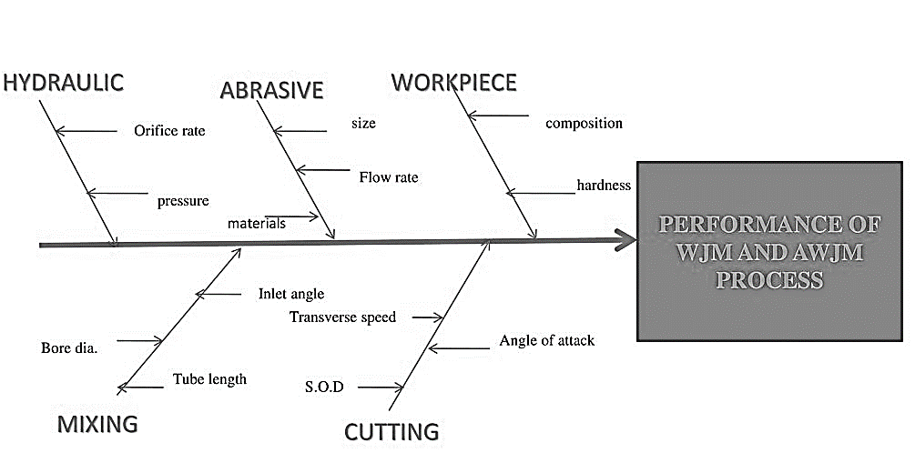
  • Fig. Process Parameters


  • MRR depends on the reactive force F of the jet.
  • Reactive force = Mass flow rate (m) X jet velocity (v)

    Hence,

    MRR α m α v

  • Depends on fluid pressure
  • Depends on fluid pressure (p) and nozzle diameter
  •  


    Q2) Explain the working of Abrasive jet machining.

    A2)

  • In AJM, the material removal takes place due to impingement of the fine abrasive particles. These particles move with the high-speed air (or gas) stream.
  • The abrasive particles are typically of 0.025 mm diameter and the air discharges at a pressure of several atmosphere.
  • Working of Abrasive jet machining (AJM):
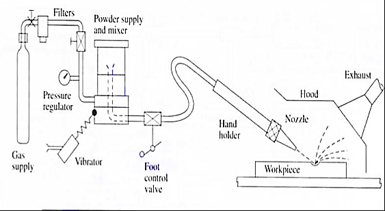
    Fig. Abrasive jet machining

  • The nozzle is made of a hard material like Tungsten Carbide here fine-grained abrasive particles are fed from the Hooper into the mixing chamber.
  • High pressure air is forced in to the mixing chamber.
  • The stream of abrasive particles bombards the work piece at a very high speed and removes the work material due to erosion.
  • The abrasive particle feed rate is controlled by the amplitude of vibration of the mixing chamber.
  •  

    Q3) Explain the principle and working of Ultrasonic machining

    A3)

    Principle of Ultrasonic machining (USM):

    In this method with the help of piezoelectric transducer tool is vibrate at high frequency in a direction normal to the surface being machined abrasive slurry are used for the remove the metal from work piece.

    Working of USM:

    Fig. Ultrasonic machining

  • The USM diagram shown in figure.
  • In ultrasonic machining a tool vibrate longitudinally at 20 to 30 kHz with amplitude between 0.01 to 0.06 mm is pressed on to the work surface with light force.
  • The electronic oscillator and amplifier are also known as generator.
  • It converts the electrical energy of low frequency to high frequency.
  • At the time high frequency current is passed through the coil therefore change in electromagnetic field which produces longitudinal strain.
  • As the tool vibrate with specific frequency the abrasive slurry mix with water and grain of definite proportion is made to flow under pressure through the tool work piece interface. The flow of slurry through the work tool interface actually causes thousands of microscopic grains to remove the work material by abrasion.
  •  

    Q4) Explain the working of EDM.

    A4)

    Electrical discharge machining (EDM), sometimes also referred to as spark machining, spark eroding, burning, die sinking, wire burning or wire erosion, is a manufacturing process whereby a desired shape is obtained using electrical discharges (sparks).

    Material is removed from the work piece by a series of rapidly recurring current discharges between two electrodes, separated by a die-electric liquid and subject to an electric voltage. One of the electrodes is called the tool-electrode, or simply the "tool" or "electrode", while the other is called the workpiece- electrode, or "workpiece".

    Working of EDM:

    Fig. Electrical discharge machining

  • The diagram of electro discharge machining shown in figure.
  • EDM is thermal erosion process whereby material is melted and vaporized from an electrically conductive work piece immerse in a liquid dielectric with a series of spark discharge between the tool electrode and the work piece created by a power supply.
  • The electrode and the work piece are separated by a dielectric medium.
  • The dielectric medium is like as kerosene, paraffin or light oil.
  • The strong electrostatic field between the electrode and work piece produce emission of electrons from the cathode.
  • In this gap between tool and work piece get ionized. The liquid is force to sparking zone.
  • Due to high temperature, the metal at the sparking zone melts instantaneously. 
  • The material of the tool is usually a material which conduct electricity and which can be easily shaped.
  • Advantages: -

  • Smaller holes can be easy machined.
  • No contact between tool and work piece then tool life is increase.
  • Any complex shape can be machined.
  • Disadvantages: -

  • Tool life is no longer.
  • Power consumption is high.
  •  

    Q5) Describe surface finish and defined their factors.


    A5) Surface finish:

    The outermost boundary of a body adjacent to the air is called surface. When this surface deformed by a sharp cutting edge, the term surface finish describes the boundary.

    A good surface is affected by many variables in single or multiple point machining.

    Surface finish is defined in terms of 4 factors:

  • Roughness – closely spaced surface irregularities, resulting from the manufacturing process or tools.
  • Lay – the overall direction of the roughness pattern which can be affected by the machine and setup.
  • Waviness – longer spaced irregularities caused by machine vibration and material warping among other factors.
  • Flaws – unique surface imperfections in the material or processing.
  •  


    Q6) Describe wire EDM in short.

    A6)

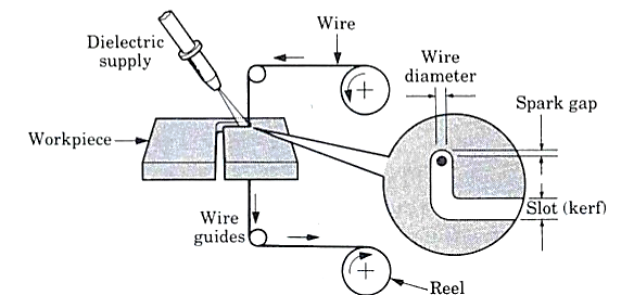
  • This process is similar to contour cutting with a band saw.
  • A slow-moving wire travels along a prescribed path, cutting the work piece with discharge sparks.
  • Wire should have sufficient tensile strength and fracture toughness.
  • Wire is made of brass, copper or tungsten. (About 0.25mm in diameter).
  • Fig. Wire EDM


    Q7) Define ECM and explain its working.

    A7)

  • Electrochemical Machining (ECM) is one of the newest and most useful non-traditional machining (NTM) process belonging to Electrochemical category.
  • Electrochemical machining (ECM) is used to remove metal and alloys which are difficult or impossible to machine by mechanical machining process.
  • The reverse of electroplating.
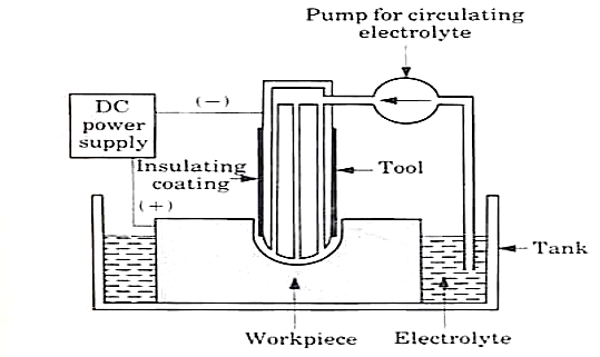
  • This machining process is based Michael Faraday’s classical laws of electrolysis, requiring basically two electrodes, an electrolyte, a gap and a source of D.C power of sufficient capacity.
  • Working of ECM:

  • In the actual process of ECM, the cathode is tool shaped (mirror image of work-piece) and anode is the work-piece.
  • A gap (0.05 to 0.7 mm) is provided between the tool and work-piece and electrolyte flows through the gap at a velocity of 30 to 60 m/s and it completes the electrical circuit.
  • Electrolyte is pumped at high pressure of 20 kgf/
    (1.96 MPa) through the gap.
  • Electrolyte must be circulated at a rate sufficiently high to conduct current between them and to carry heat.
  • Metal is removed from the work-piece by dissolution
  • The electric current is of the order of 50 to 40,000 A at 5 to 35 V D.C for current density of 20 to 300 A/
    .
  • Power of 3 KWh is needed to remove 16
    of metal which is almost 30 times the energy required in the conventional process (when the material is readily machinable).
  • Fig. Electro-chemical machining


    Advantages of ECM:

  • Process leaves a burr free surface.
  • Does not cause any thermal damage to the parts.
  • Lack of tool force prevents distortion of parts.
  • Capable of machining complex parts and hard materials.
  • ECM systems are now available as Numerically Controlled machining centers with capability for high production, high flexibility and high tolerances.
  •  


    Q8) Explain MRR.

    A8)

    Material removal rate (MRR):

  • Material removal rate (MRR) is an important characteristic to evaluate efficiency of a non-traditional machining process.
  • In ECM, material removal takes place due to atomic dissolution of work material which is governed by Faraday’s laws of Electrolysis.
  • MRR = m / tρ = IA / Fρν

    where m = ItA/Fv = mass of material dissolve

    I = current

    A = Atomic weight

    v = valency

    F = Faraday’s constant = 96500 coulombs

    ρ = density of the material

    Power Supply:

    1. Type: direct current

    2. Voltage: 2 to 35 V

    3. Current: 50 to 40,000 A

    4. Current density: 20 A/cm2 to 300 A/cm2


    Q9) Explain the working of the Laser-beam machining.

    A9)

    Laser-beam machining is a thermal material- removal process that utilizes a high-energy, coherent light beam to melt and vaporize particles on the surface of metallic and non- metallic work pieces.

    Lasers can be used to cut, drill, weld and mark. LBM is particularly suitable for making accurately placed holes.

    Principle of Laser beam machining (LBM):

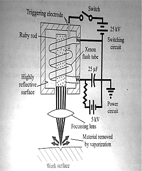
  • Conversion of electrical energy into heat energy to emit laser beam energy.
  • Laser beam is focused on lance then create high energy the high energy concentration on work piece then work piece is melt and vaporized of metal.
  • Working of LBM

    Fig. Laser Beam Machining

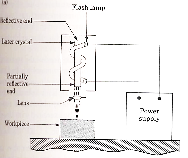
  • The diagram of LBM is shown in figure.
  • Laser is stand for Light Amplification by Simulated Emulsion of Radiation.
  • The work piece is placed on the aluminum work table which material is hard not cut by laser beam.
  • Ruby rod is used into form of cylindrical crystal both ends of ruby rod are finished to optical tolerance.
  • The flash lamp wound around the ruby rod and connected to power supply.
  • The ruby rod becomes highly efficient on low temperature and low efficient on high temperature. It is thus continuous cooled with water, air or liquid nitrogen.
  • When the light beam has been amplified sufficiently and intensity beam of light comes out form partially reflected end it is focused on the work piece at the focused very high temperature which vaporized and removes the metal on work piece.
  • Applications: -

  • LBM can make very accurate holes as small as 0.005 mm in refractory metals ceramics, and composite material without warping the work pieces.
  • It is used for welding of thin metal sheet.
  • Leaser can be used for cutting as well as drilling.
  • Heat treatment.
  • It is used for cutting complex profile.
  •  


    Q10) Explain the Plasma Arc Machining process.

    A10)

    Plasma Arc Machining is used to remove material from the workpiece. In this process, a high velocity jet of high-temperature gas is used to melt and remove material from the workpiece. This high velocity of hot gas is also known as plasma jet.

    When a gas or air is heated at a temperature of more than 5000 °C, then it will start getting ionized into positive ions, negative ions and neutral ions. When the gas or air is ionized its temperature reaches from 11000 °C to 28000 °C and this ionized gas is called plasma.

    The gas or air is heated with arc and the plasma produced by heating gas is used to remove material from the workpiece. So, the whole process is called Plasma Arc Machining.
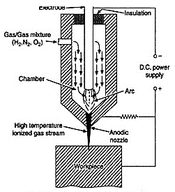
    Fig. Plasma Arc Machining

  • In this case, the high velocity electrons of are collide with the gas molecules & metal to form ionization of beam.
  • The plasma gas is forced through nozzle duct & is made to direct on the work piece to be machined.
  • Much of the heating takes place in duct at about 1600 degree Celsius & metal removal is due to electron bombardment & hot plasma.
  • Mechanism of Metal Removal:

  • The metal removal in PAM is due to high temperature of gases.
  • The heating of work piece is due to direct electron bombardment plus convective heating of hot plasma.
  • The heat produced is sufficient to raise the temperature above its melting point.  Approximately 45% of electrical power delivered to torch is used for removal metal from work piece.
  • PAM is used for cutting, spraying, & surfacing operations.
  •  

    Advantages of Plasma arc Machining:

  • Rapid Cutting Speeds:
  • Plasma arc cutting is faster than oxyfuel for cutting steel up to 50 mm thick and is competitive for greater thickness.
  • Plasma cutting achieves speeds greater than those of laser cutting systems for thickness over 3 mm.
  • The fast-cutting speeds result in increased production, enabling systems to pay for themselves in as little as 6 months for smaller units.
  • 2.     Wide Range of Materials and Thickness:

  • Plasma cutting systems can yield quality cuts on both ferrous and nonferrous metals. Thickness from gauge to 80 mm can be cut effectively.
  • 3.     Easy to Use:

  • Plasma cutting requires only minimal operator training. The torch is easy to operate, and new operators can make excellent cuts almost immediately. Plasma cutting systems are rugged, are well suitable for production environments, and do not require the potentially complicated adjustments associated with laser cutting systems.
  • 4.     Economical:

  • Plasma cutting is more economical than oxyfuel for thickness under 25 mm, and comparable up to about 50 mm. For example, for 12 mm steel, plasma cutting costs are about half those of oxyfuel.
  •  

    Disadvantages of Plasma Arc Machining:

  • The cutter's electrode and nozzle sometimes require frequent replacement which adds to the cost of operation.
  • Non-conductive materials such as wood or plastic cannot be cut with plasma cutters with transferred arc type.
  • Another minor drawback is that the plasma arc typically leaves a 4–6-degree bevel on the cut edge, although this angle is almost invisible on thinner material, it is noticeable on thicker pieces.
  •