Unit - 3
Fluid Dynamics
Q1) What is fluid dynamics?
A1)
- The study of force which produced motion in a fluid is called fluid dynamic. Newton's second law of motion is the fundamental principle on which fluid dynamics are based.
- It states that, the resultant force on the fluid element is directly proportional to the rate of change of momentum and take place in the direction of force.
- Net force = Mass x Acceleration
∴ ΣF = m.a
Q2) What are Non-dimensional number?
A2)
The ratio of two forces is called as dimensionless parameter or number. The following are the important dimensionless numbers used in fluid mechanics.
- Reynold's number
- Froude's number
- Weber's number
- Euler's number
- Mach's number.
Reynold’s Number:
- The ratio of inertia force to the viscous force is called as Reynold's number. It is denoted by Re.
=
=
=
=
= =
=
= =
= =
= =
= ∵v=
∵v=
Applications of Reynolds number:
- Motion of completely submerged bodies like submarine, aeroplanes and automatic with low velocity, Incompressible flow through pipes, flow through low-speed turbo machine in which viscous forces are predominant.
Froude's Number:
- The square root of the ratio of inertia force and gravitational force is called Froude's number. It is denoted by F
∴Fr=
=
=
= ∵V=
∵V= =T=
=T=
= =
= =
=
Application:
- Open hydraulic structure such as spillways, wiers, open channel flow, sluices etc. in which force due to gravity are predominant.
Weber's Number
- The square root of the ratio of the inertia force to the surface tension force. It is denoted by We.
We= =
=
= ∵A/T=Q=V.A
= ∵A=L2=
Application:
- Capillary movement of water in soils, flow of blood in veins and arteries where the surface tension effects are predominant.
Euler's Number:
- The square root of the ratio of inertia force to the pressure force is called as Euler's ratio.
= =
=
= =
= =
=
= ∵A/T=Q=V.A
Application:
- In cavitation study where pressure force is predominant.
Mach's Number or Cauchy's Number:
- The square root of the ratio of inertia force to the elastic force is called as Mach's number or Cauchy's number.
MN = =
=
= =
= =
=
= ∵A/T=Q=V.A
Application:
- In compressible fluid flow, problems at high speed such as high velocity flow in pipes, water hammer, motion of high-speed objects like aeroplane, projectile and missiles. Where the elastic force (compressibility effect) is predominant.
Q3) Explain Euler’s equation along a streamline?
A3)
- Consider steady flow of an ideal fluid along the shown tube.
- Separate out a small element of fluid of cross- sectional area dA and length ds from stream tube as a free body from the during fluid.
- Fig. Shows such a small elements LM of fluid of cross Section area dA and length ds.
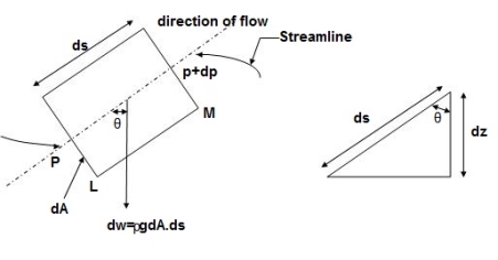
Fig.: Equation of motion Diagram
- Let, p= Pressure of the elements at L
p + dp = Pressure on the element at M, and
V=Velocity of the fluid element.
- The external forces tending to accelerate the fluid elements in the direction of streamline are as follows:
- Net pressure force in the direction of flows is, p.dA – (p+dp)dA = -dp. DA
- Component of the weight of the fluid elements in the direction of flows is
= - .g.dA.ds.cos
=-  .g.dA.ds (dz/ds) (:. Cos = dz/ds)
= -  .g.dA.dz
- Mass flow of the fluid element =
 .dA.ds
 - The Acceleration of the fluid element,
a = dv/dt = dv/ds * ds/dt = v. Dv/ds
- Now, according to Newton’s second law of motion, force= mass x acceleration.
∴ – dp. DA. -  .g.dA.dz=
 .dA.ds x v.dv/ds
Dividing both sides by rho. DA, we get
-dp/- . g.dz= v.dv
Or dp/ + v. Dv + g.dz=0
- This is the required Euler’s equation for motion.
Integrating the Euler’s equation of motion, we get
1/ ∫ d p +∫v. d v+ ∫g.dz=constant
p/ ρ + v2 /2 + g z = constant
Dividing by g, we get
p/  g + v 2/2g + z = constant
p /w + v 2/2g + z = constant
Or in other words, P1/ W+V1 2 / 2 g +Z1=P2/ W+V22 / 2g+Z2
Which proves Bernoulli’s equation.
Q4) Explain Bernoulli’s equation & its application to siphon?
A4)
- Bernoulli's equation is based on Euler's theory of fluid flow and it obtained by integrating the Euler's equation of motion.

Integrating,

For incompressible flow,  is constant

This equation is called as Bernoulli's equation.
Bernoulli's Theorem:
- It states that in a steady, ideal flow of an incompressible fluid, the total energy at any point of the fluid is always constant.
∴Total Energy = constant
Pressure energy+ Kinetic every + Potential energy = Constant
∴ 
Where, = pressure energy or pressure head per unit weight
 kinetic energy or kinetic head per unit weight
Z = potential energy or datum energy or datum head per unit weight
Assumptions made in Bernoulli's Equation:
- The fluid is ideal.
- The flow is steady and continuous,
- The flow is incompressible.
- The flow is one-dimensional i.e., along steam-line.
- Velocity is uniform over the cross-section and is equal to the mean velocity.
- The gravity force and pressure force are curly considered.
- The flow is irrotational.
Modified Bernoulli’s Equation
- All practical fluids are viscous and offer resistance to fluid flow. So that there are some losses in fluid flow between two sections. Bernoulli's equation was derived on the assumption that fluid is non-viscous i.e., frictionless. Which is not applicable of practical fluid and hence Bernoulli's equation is modified by considering losses.
- Modified Bernoulli's equation for real fluid.

Where hL = loss of energy between point 1 and 2.
Modified Bernoulli's equation in K.E. Correction factor ' ' considered

Modified B.E. If some energy is taken out from 1 to 2

Modified B.E. If energy is added from 1 to 2.

Limitation of Bernoulli's Equation:
- It is applicable to ideal incompressible flow.
- The heat transfer into or out of fluid should be zero.
- The temperature remains constant so that internal energy does not change.
- The effect of presence of any mechanical device between two sections is ignored.
Practical Applications of Bernoulli's Equation
- Orifice meter
- Submerged orifice
- Venturi-meter
- Pitot tube
- V-notch
Q5) Explain about Venturimeter?
A5)
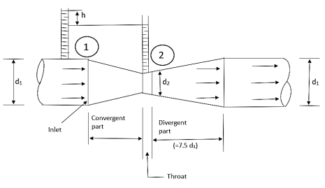
Fig: Venturimeter
Use:
- Venturimeter is the device used for measuring the rate of flow of fluid flowing through the pipelines.
Principle:
- It is based on Bernoulli’s equation that is the velocity head increases in an accelerated flow by reducing the cross-sectional area of the flow passage. Due to which the pressure head is reducing at that section, a pressure difference is created which enables to the determination of the discharge through the pipe.
Construction:
- It consists of a short converging conical tube which has a total included angle of 21 ± 1° leading to a cylindrical portion of short length, known as throat, diameter of throat varies 1/3 to ¾ between roof main pipe diameter, (preferable ½) which is followed by a diverging section Known as diffuser having total included angle 5° to 7° (preferably 6%) which is again connected to the main pipe lines.
- Angle of diversion cone is smaller because when water is passing through throat, its velocity is more since area as throat is less.
- As this water passes through diversion cone there is chance of separation of fluid flow from boundary of diversion cone causing cavitation. That is why to increase area of flow gradually, the angle of divergent cone is less and its length is more.
- The pressure difference from which the volume rate of flow can be determined is measured between the entry section 1 and the throat section 2, often by means of a U-tube manometer.
- The axis of venturimeter may be horizontal or inclined or vertical.
Derivation
- Consider a venturimeter fitted in a horizontal pipe through which a fluid is flowing as shown in Fig.
Let
P₁ = Pressure at section 1,
V₁ = Velocity at section 1,
a₁= Area at section 1,
Z₁ = Datum head at section 1
P2, V₂, a2, Z₂ are the corresponding value at section 2
Assuming that is no loss of energy and apply Bernoulli's equation to section

Since the meter is horizontal Z₁ = Z₂

∴
 is the pressure head difference between section 1 and 2, and it is denoted by h.
∴h= … (1)
… (1)
Now applying continuity equation,
Q = a₁V₁= a₂ V₂
V₁ = …... (2)
Put the value of V1 in Equation (1)
∴ h= =
=
=  …. (3)
∴
∴  …. (4)
Discharge through venturimeter
Q= …. (5)
This is the discharge under ideal condition, called as theoretical discharge.
But Actual discharge = Coefficient of discharge x Theoretical discharge
Q =  … (6)
… (6)
Where Cd= Coefficient of discharge
Differential pressure head for venturimeter (h)
- Case 1: Differential nanometer contains a liquid heavier than the liquid flowing through pipe.

Where X=Deflection in manometric liquid in U-tube
Sm = Specific gravity of manometric liquid
S = Specific gravity of flowing liquid.
- Case 2: Differential manometer contains a liquid the liquid flowing through pipe.

- Case 3: When pressure head at section 1 and 2 known,
 +
+
If venturimeter is horizontal, Z₁ = Z₂

Q6) Explain about Orificemeter?
A6)
- Orifice meter is a device used to determine the rate of flow through pipe.
- It consists of flat circular plate which has sharp edge hole called orifice concentric in pipe.
- The orifice diameter is generally kept half of the diameter of the pipe.
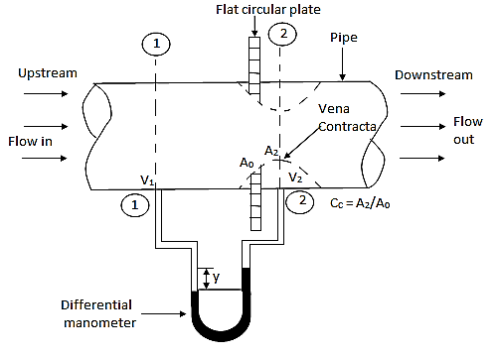
Fig: Orificemeter
- It is based on the same principle of venturimeter.
- The value of Cd, varies between 0.60 to 0.65
- This is economical and less space is required for fitting.
Consider an orificemeter fitted in a horizontal which fluid is flowing.
Let P1= Pressure at section 1,
V₁ =Velocity at section 2
a₁= Area at section 1,
Z1= Datum head at section 1
 are the corresponding value of section 2 i.e., at orifice.
Assuming no loss of energy and apply Bernoulli's equation at section 1 and 2.

Since the pipe is horizontal, Z1 = Z0

∴ … (1)
… (1)
Applying continuity equation
Q=
∴ … (2)
… (2)
Substitute, the value of V1 in Equation (1)

∴2gh=
∴
∴ …. (3)
Discharge through orificemeter

This is the theoretical discharge.
Now,
Actual discharge = 
Q = 
Where, Cd = Coefficient of discharge.
Q7) What is Pitot tube?
A7)
- A pitot tube is the simple device used for measuring the velocity of the flow at the required point in a pipe or a stream. It is also called as impact tube or stagnation tube.
- It is based on the principle that if the velocity of flow at a point becomes zero, the pressure is increased due to conversion of kinetic energy into pressure energy.
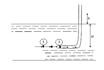
Fig.: Pitot tube
- In its simple form, a pitot tube consists of a transparent glass tube bent through 90° and with ends unsealed.
- Diameter of tube is larger enough to neglect capillary effects.
- One leg called as the body is inserted into the flow at upstream and aligned with the direction of flow whereas the other leg, called as stem, is vertical and open to atmosphere.
- The liquid is rise in the tube due to changes in energy.
- The velocity is determined by measuring the rise in the tube.
- Consider a section 1 and 2 at a same level just in front of inlet of the tube.
Apply Bernoulli's equation

∴ Z₁ = Z₂ as they are at same level
V₂ = 0 because flow of particle comes to rest at point 2.
h =Rise in tube,
H = Head of pressure at 1 (static head)
h+H = Stagnation head
Substitute above value in Bernoulli's Equation (1)
∴H+ =h+H ∴h=
V₁ = 
This is the theoretical velocity.
Actual velocity
V = Cv, Vtheoretical = Cv =
Where Cv= Coefficient of velocity
Q8) Explain Loss due to friction?
A8)
- The major loss of energy is due to friction. It is determined by Darcy-Weisbach formula
 Darcy-Weisbach formula
Where, f = Darcy's coefficient of friction;
C = Chezy's constant.
- The loss due to friction is much more in case of long pipelines as compare to other losses and hence it is classified as a major loss. It depends on roughness of pipe, length, velocity and diameter of pipe.
Q9) Explain Minor energy losses in pipes?
A9)
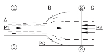
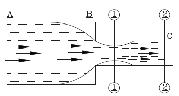
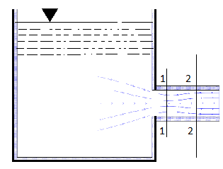
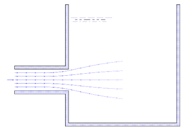
- The losses due to disturbance in the flow pattern is called as minor losses.
- It occurs due to sudden contraction or expansion, valves, fittings, bends etc. and at entrance and exit from pipe.
- In case of short pipe, minor losses are to be consider. Whereas in long pipe, it does not make any serious effect.
Loss due to sudden enlargement,

Loss due to sudden contraction,

 if Cc is not given.
Loss at the entrance,

Loss at exit from pipe,
hL= 
Loss due to bends or pipe fitting,

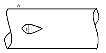
Head loss due to an obstacle in a pipe,

Q10) What is Hydraulic Gadient line?
A10)
- It is the sum of pressure head and datum head w.r.t. Datum line.
- Hydraulic grade line less below total energy line by
 .
.
Q11) What is Total energy line?
A11)
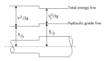
- Total energy line is the sum of velocity head, pressure head and datum head.
- Total energy line has above hydraulic grade line by

Q12) Explain Power transmission in the fluid flow in pipes?
A12)
- Power is transmitted through pipe by allowing water to flow through a pipe.
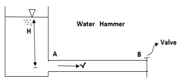
- Now consider a pipe AB connected to a tank as shown in Fig.
Let,
H = Head of water at inlet
L = Length of the pipe
d = Diameter of the pipe
V = Velocity of flow in pipe
hf = Head loss due to friction
Head available at the outlet of the pipe,
= Head at inlet - Head loss due to friction =H-
Weight of water flowing through pipe/sec.
W = x Volume of water/sec.
= x Area x Velocity =
Power transmitted at outlet of the pipe,
P = Weight of water per sec x Head at outlet
P= … (1)
… (1)
Efficiency of power transmitted,
ɳ=
ɳ=
=
ɳ=
Condition for Maximum Transmission of Power:
- The condition for maximum transmission of power is obtained by differentiating Equation 1 with respect to V and equating the same to zero.
∴


H=
∴
- The Equation is the condition for maximum transmission of power.
Maximum Efficiency of Transmission of Power:
- Efficiency of power transmission through pipe is given by, ɳ=

- For maximum power transmission,

∴Maximum efficiency, ɳ=
∴ɳ% = 66.67%
Q13) Explain Fluid flow in pipes in series?
A13)
- When the pipes of different lengths and diameters are connected to each other to form a pipeline then such a pipeline is called as a compound pipe or pipes in series.
- As the pipes are in series, the discharge through each pipe will be same (continuous)

- If a pipeline connecting two reservoirs by compound pipes, then the difference in liquid surface level is equal to the sum of the head losses in all the sections.
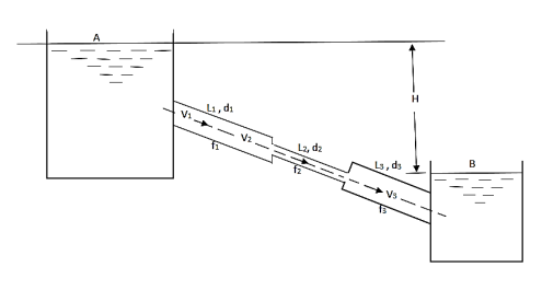
Let Q = Discharge through pipeline
H = Total loss of head
d₁ = Diameter of pipe 1
L₁ = Length of pipe 1
f₁ = Darcy's coefficient of friction
d2, L2, f2 =Corresponding value of pipe 2,
d3, L3, f3 =Corresponding value of pipe 3.
1. Considering all losses,
Total loss of head = Major losses + Minor losses
H=
∴Major losses = Head loss due to friction in each pipe

=
∴Minor losses = Entrance loss+ Contraction loss+ Expansion loss+ Exit loss

2. If minor losses are neglected, then Total loss of head = Major losses

3. If discharge through the pipe is given, then
H=
Q14) Explain Fluid flow in pipes in parallel?
A14)
- When a pipeline divides into two or more parallel pipes which again join together at downstream as shown in Fig., then that pipe is said to be in parallel.
- In order to increase the discharge passing through the main pipe, the pipes are connected in parallel.
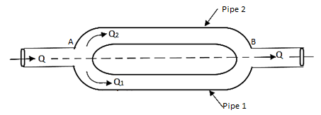
- The discharge in the main pipe is equal to sum of the discharge in each of the parallel pipes.
∴Q =
- When the pipes are arranged in parallel, the loss of head in each parallel pipe is same.


Q15) Water is flowing through a tapered pipe having diameters 300 mm and 150 mm at section 1 and 2 respectively. The discharge through the pipe is 40 litre/sec. Section 1 is 10 m above datum and section 2 is 6 m above datum. Find the intensity of pressure at section 2 if that at section 1 is 400KN/m2.
A15)
Given
Q = 40 litre/sec=0.04 m²/sec
Z₁ = 10m
Z₂ =6m
d₁ =300mm=0.3 m
d2 = 150 mm-0.15m
P1 = 400 kN/m²
To find: P:
Area


By continuity equation,


By Bernoulli's equation


The intensity of pressure of section 2 is 436.84 kN/m²
Q16) A pipe has a length of 200 m with a slope of 1 in 100. The diameter of pipes changes from 1.0 m at higher end to 0.5 m at lower end. Find the pressure at the lower end if the discharge flowing through pipe is 5.00 m/min and pressure at higher end is 45 kN/m².
A16)
Given:
L = 200 m,
P₁ =45 kN/m²
Slope = 1 in 100. z₁ = 0,
d₂ -0.5 m
Q = 5 m/min =5/60 = 0.0833 m/sec
To find: P₂
Slope of pipe is 1 in 100


(Since it is below z₁ i.e., datum, it is considered negative) = -2m
By continuity equation


By Bernoulli's equation


Multiplying by 9.81

Q17) The top and bottom diameters of a 2m long vertical tapering pipe are 100 mm and 50 mm respectively. Water flows down the pipe at 30 liters por second. Find the pressure difference between the two ends of the pipe.
A17)
Given:
Q = 30 Lps = 0.03 m³/sec,
d1 = 0.05 m. d₂ = 0.1 m, z₁ = 0, z₂ = 2 m
Area


By continuity equation,


By Bernoulli's equation


:. The pressure difference between two ends of pipe is 10.415x 10³ Pa
Q18) A venturimeter has an area ratio 9.1, the large diameter being 30 cm. During the flow, the recorded pressure head in the large section is 7.75 m and that at the throat is 5.5 m. Find the discharge through the meter if C,0.98.
A18)
Given:


Discharge of inlet
d1 = 0.3 m
Pressure at inlet 
Pressure head at throat 
Coefficient of discharge Cd, = 0.98
Area


Pressure head

Discharge


Q19) A venturimeter is to be fitted to a pipe of area 0.01787 m² A maximum discharge of 5 m/min under a pressure of 4.5 m flows through the pipe. Find the diameter at the throat for no negative pressure at the throat.
A19)
Given:
a1 = 0.01767 m². Q = 5 m²/min=0.08333 m/sec
Pressure head = 4.5 m
To find: Diameter of throat i.e., d
Considering the venturimeter to be horizontal
Applying Bernoulli’s equation at section (1) and (2)


But Z1=Z2
And as there is no negative pressure at throat considering


Discharge Q

(Assuming C=0.98)


Q20) A venturimeter is fitted to 25 cm diameter pipe. A discharge 10 m³/s flowing through venturimeter, develops a venturi head of 3.5 m of water. Find the minimum diameter of throat so that there is no negative head developed.
A20)
Given:
D = 25 cm = 0.25 m, Q = 10 m³/s,
To find:
d for no negative head developed.
a₁ = area of inlet = 

Cd=1


Squaring both side


Q21) A pitot tube records of 7.85 kN/m² as the stagnation pressure when it is head at the centre of pipe of 250 mm diameter conveying water. The static pressure in the pipe is 40 mm of mercury (gauge-vacuum). Calculate the discharge through the pipe assuming that the mean velocity of flow is 0.8 times the maximum velocity. Take C, = 0.98.
A21)
Given:
Stagnation pressure p₁= 7.85 kN/m²
Pressure at center of pipe = 40 mm of mercury
P2 = -0.04×13.6 x 9.81-5.336 kN/m
Mean velocity = 0.8 x maximum velocity
Pressure head

Maximum velocity

Mean velocity (V)=0.8 x Maximum velocity = 0.8 x 5.033=4.0264 m/sec
Discharge Q

Discharge through the pipe 197.65 Lps.
Q22) A pitot static tube is used to measure velocity of an aeroplane. U-tube differential manometer gives deflection of 100 mm of water. If specific weight of air is 12 N/m and coefficient of pitot tube is 0.98. Determine speed of aeroplane. Neglect compressibility effects.
A22)
Given:
C = 0.98. Ya = 12 N/m².
x = 100 mm of water = 0.1m
To find: Speed of aero plane V =?
Specific gravity of air

Specific gravity of water
Sw = 1

Speed of aircraft

The speed of aeroplane is 39.28 m/s.
Q23) An Orifice of diameter 12 cm is inserted in a pipe of 24 cm diameter. The end pressure gauge fitted upstream and 2 downstream of the orifice metre gives readings 29.43 N/cm and 14.72 N/cm respectively. Co-efficient of discharge of orifice metre is given by 0.6. Find the discharge of water through pipe.
A23)
Given:
d, = 24 cm = 0.24 m, p, 29.43 N/cm² = 294.3 kN/m² 4-12 cm-0.12 m. p₂= 14.72 N/cm² Cv= 0.6
Area A₁


Pressure difference

Discharge, Q


The discharge through the pipe is 120 Lps.
Q24) Two reservoir at different elevations are connected with a compound pipe of 1 km total length; consisting of two sections. First section connect to higher level reservoir is 500 m long and 200 mm in a diameter and other half is connected to lower-level reservoir and has 100 mm diameter. Darcy Weisbach friction factors for the pipes are 0.019 and 0.02 respectively. If velocity of flow of water in the second section is 1.5 m/s. Find the difference in water levels in the reservoirs considering all losses. Find the rate of flow of water also. Find diameter of single uniform diameter pipe replace the above pipeline to carry same discharge. Take f = 0.018 for the pipe.
A24)
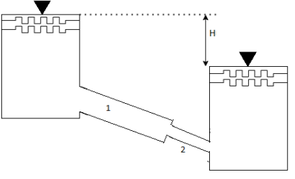
Given:
d₁= 200 mm = 0.2 m
f₁ = 0.019 d₂ = 100 mm = 0.1 m
f₂ = 0.02
L = 1 km
By continuity equation,
A₁V₁ = A₂V₂


Case I:
Major losses = Loss due to friction Loss due to friction in pipe 1 in pipe 2


Minor losses = Loss at entry + Loss due to contraction + loss at exit


Total losses = Major losses+ Minor losses

Case II: New pipe with uniform diameter


The diameter of single equivalent pipe is 114.16 mm.
Q25) Three pipes 300 m, 150 m, 200 m long having diameters 300 mm, 200 mm and 250 mm respectively are connected in a series in the same order. Pipe having 300 mm diameter in connected to the reservoir. Water level in the reservoir is 15 m above the pipe are 0.018, 0.02 and 0.019. Determine the flow rate, magnitude of loss in each pipe section, and the diameter when the three pipes are replaced by a single pipe (f = 0.016) to give the same discharge. Neglect the minor losses.
A25)
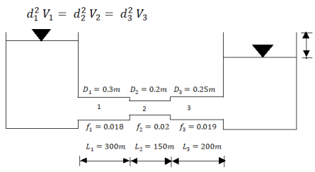
Let V, V, and V, are the velocities in the pipe 1, 2, 3 respectively.
By continuity equation


Major loss = hf1+hf2+hf3


Flow rate

Head loss in each pipe


Diameter when three pipes are replaced by single pipe
Using Dupit’s equation

