Unit - 3
Design of highway pavements
Q1) Explain design of highway pavement in detail.
A1) Design of highway pavements:
In addition to these, composite pavements are also available.
Q2) What do you mean by flexible pavement?
A2) Flexible Pavement
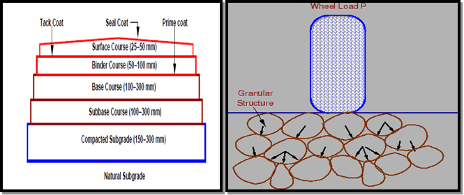 Fig.: Flexible Pavement
A flexible pavement invariably consists of all the courses as shown in Fig 9. Thus, it is a multi-layered system with low flexural strength.
The external loads are largely transmitted to the sub grade through the intervening layers-the base and the sub-base – by means of interlocking at the grain-to-grain contacts in the granular structure.
Lateral distribution of the compressive stresses on to a larger area with increasing depth is the basic mechanism of stress transfer.
The thicknesses of the intervening courses are so designed as to keep the stresses transferred to the sub grade soil less than the allowable bearing pressure to ensure that deformations or settlements remain within permissible limits.
Q3) Explain rigid pavement with neat sketch.
A3) Rigid Pavements
A rigid pavement, in contrast to a flexible one, derives its capacity to resist loads by virtue of its flexural strength.
Flexural strength allows the pavement to bridge over minor irregularities or weak spots in the sub grade or other courses such as the base or sub-base upon which it rests.
Thus, the inherent strength of the pavement slab itself plays a major role in resisting the wheel loads; this, however, cannot under-rate the need for a strong sub grade.
It simply means that, provided a certain minimum support is derived from the sub grade, the performance of the rigid pavement is governed by the strength of the pavement slab rather than by that of the sub grade.
Rigid pavements consist of cement concrete (OPC), which may be plain, reinforced or pre-stressed concrete.
The primary difference between a rigid pavement and a flexible one is in the structural behavior; the critical condition of stress is the maximum flexural stress in the pavement slab not only due to the wheel load, but also due to warping caused by changes in temperature in the summer and winter seasons, and during the day and night.
The warping of the slab is caused by the temperature gradient between the top and bottom, and the consequent flexure.
Further, temperature changes tend to cause stresses due to friction at the interface between the slab and the layer below, which opposes the movement of the slab.
A rigid pavement can serve the dual purpose of a base and a wearing course. However, it is not normally laid directly over the sub grade when the latter consists of fine-grained soil.

Fig.: Typical Cross section of Rigid pavement
Rigid pavements can be classified into four types:
Q4) Explain flexible pavement and their design I detail.
A4) Flexible pavements and their design
Flexible pavements are so named because the total pavement structure deflects, or flexes, under loading. A flexible pavement structure is typically composed of several layers of materials. Each layer receives loads from the above layer, spreads them out, and passes on these loads to the next layer below. Thus, the stresses will be reduced, which are maximum at the top layer and minimum on the top of subgrade. In order to take maximum advantage of this property, layers are usually arranged in the order of descending load bearing capacity with the highest load bearing capacity material (and most expensive) on the top and the lowest load bearing capacity material (and least expensive) on the bottom.
For flexible pavements, structural design is mainly concerned with determining appropriate layer thickness and composition. The main design factors are stresses due to traffic load and temperature variations. Two methods of flexible pavement structural design are common today: Empirical design and mechanistic empirical design.
An empirical approach is one which is based on the results of experimentation or experience. Some of them are either based on physical properties or strength parameters of soil subgrade. An empirical approach is one which is based on the results of experimentation or experience. An empirical analysis of flexible pavement design can be done with or without a soil strength test. An example of design without soil strength test is by using HRB soil classification system, in which soils are grouped from A-1 to A-7 and a group index is added to differentiate soils within each group. Example with soil strength test uses McLeod, Stabilometer, California Bearing Ratio (CBR) test. CBR test is widely known and will be discussed.
There are three different approaches for considering vehicular and traffic characteristics, which affects pavement design.
Fixed traffic: Thickness of pavement is governed by single load and number of load repetitions is not considered. The heaviest wheel load anticipated is used for design purpose. This is an old method and is rarely used today for pavement design.
Fixed vehicle: In the fixed vehicle procedure, the thickness is governed by the number of repetitions of a standard axle load. If the axle load is not a standard one, then it must be converted to an equivalent axle load by number of repetitions of given axle load and its equivalent axle load factor.
Variable traffic and vehicle: In this approach, both traffic and vehicle are considered individually, so there is no need to assign an equivalent factor for each axle load. The loads can be divided into a number of groups and the stresses, strains, and deflections under each load group can be determined separately; and used for design purposes. The traffic and loading factors to be considered include axle loads, load repetitions, and tyre contact area.
Q5) Give review of old methods in detail.
A5) Review of old methods
In fairness, the Carthaginians are generally credited with being the first to construct and maintain a road system (about 600 B.C.) according to Tillson [1900]. The Romans eventually decided that their neighbors across the Mediterranean were a bit of a threat to the empire destroying Carthage in 146 B.C. (The Carthage ruins are located in Tunisia (Northern Africa) next door to Algeria (on the left) and Libya (on the right — so to speak).) It is suggested that the Romans took up the practice of a military road system from the Carthaginians. It is estimated that the Romans built about 87,000 km of roads within their empire (about equal to the length of the U.S. Interstate system).
The Roman design for their primary U.K. roads generally consisted of four layers (top to bottom) as follows [Collins and Hart, 1936]:
The total thickness was as much as 0.9 m and road widths of 4.3 m or less. An illustration of Roman pavement structure near Radstock, England, is shown as Figure 1. Roman roads in some countries have been up to 2.4 m thick. These structures had crowned (sloped) surfaces to enhance drainage and often incorporated ditches and/or underground drains.
As one might expect, Roman road building was varied to suit local conditions and materials — not unlike today actually. The Romans departed the U.K. about AD 406. Road design and construction languished for about 1,200 years thereafter.
Unlike the stone roads constructed in ancient times, roads today are not designed or constructed to last forever, mainly for economical reasons. In most US states, roads are typically designed to last 15 to 20 years. Though, with frequent and proper maintenance, the design life may be extended considerably. Typically, the cost of reconstruction of a deteriorated road due to lack of maintenance may be more than three times the cost of preserving a frequently maintained road. Road conditions are an important factor in the US economy and leading civil engineering institutions, such as the American Society of Civil Engineers (ASCE), continue to produce articles regarding the need to improve roads and other infrastructures. According to, currently half of the major roads in the US are considered in poor condition with almost 25 % of roads in urban areas (and in some areas even up to 60 %) considered poor. Researchers such as have been reviewing the conditions of America’s highways since 1983 to provide awareness to the general public and legislators.
The cost of maintenance and rehabilitation is high. In 2008, an estimated $182 billion were spent in the US on capital improvements and maintenance of federal highways. Although billions are spent annually, many consider this insufficient. For example, the ASCE currently gives the nation’s transportation infrastructure (which includes not only roads and bridges, but dams, rail, levees, etc.) an overall grade of D (on a traditional grading scale ranging from A-F) and estimates $2.2 trillion in improvements are needed.
Q6) What is CBR test?
A6) California Bearing Ratio (C.B.R.) Test
The California Bearing Ratio (CBR) test is a measure of resistance of a material to penetration of standard plunger under controlled density and moisture conditions.
It was developed by the California Division of Highways as a method of classifying and evaluating soil- sub grade and base course materials for flexible pavements.
CBR test may be conducted in remolded or undisturbed sample. Test consists of causing a cylindrical plunger of 50mm diameter to penetrate a pavement component material at 1.25mm/minute.
The loads for 2.5mm and 5mm are recorded.
This load is expressed as a percentage of standard load value at a respective deformation level to obtain CBR value.
The aim of this test is the determination of California Bearing Ratio value of the sub grade soil.

Q7) Explain the procedure of CBR test.
A7) Procedure of California Bearing Ratio Test
CBR (%) =  100
100
CBR(2.5mm) =  X 100
X 100
CBR(5.0mm) =  X 100
X 100
CBR = Higher of CBR2.5 mm/ CBR5.0 mm
Standard Load (2.5 mm Penetration) = 1370 Kg
Standard pressure/stress @ 2.5 mm = 
= 70 Kg/cm2
Standard pressure/stress @ 5.0 mm = 
= 105 Kg/cm2
CBR of a soil sample is average of CBR of three specimens prepared from same sample.
Generally, 2.5 mm CBR is more than 5 mm CBR. But if 5 mm CBR is more than 2.5 mm CBR, than test must be rep Repeated again and again. If same result comes then higher value is considered as CBR i.e., CBR @ 5 mm.
Empirical formula for thickness, (T)cm= 
(Applicable for CBR>12%)
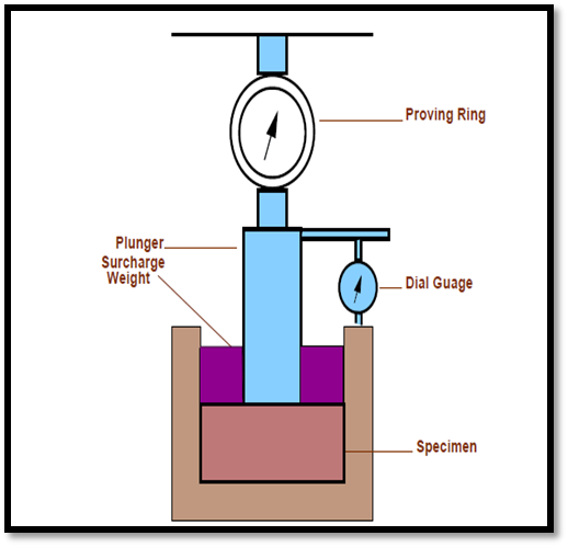
Fig.: California Bearing Ratio Test
Q8) Why IRC: 37-2012 is used?
A8) IRC: 37-2012
1. The guidelines on design of flexible pavement were first brought out in 1970, which were based on California Bearing Ratio (CBR) of subgrade and traffic in terms of number of commercial vehicles (more than 3 tones laden weight). These guidelines were revised in 1984 in which design traffic was considered in terms of cumulative number of equivalent standard axle load of 80 kN in millions of standard axles (msa) and design charts were provided for traffic up to 30 msa using an empirical approach.
2. The guidelines were revised again in 2001 when pavements were required to be designed for traffic as high as 150 msa. The revised guidelines used a semi-mechanistic approach based on the results of the MORTH’s research scheme R-56 implemented at IIT Kharagpur. The software, FPAVE was developed for the analysis and design of flexible pavements. Multilayer elastic theory was adopted for stress analysis of the layered elastic system. A large number of data collected from different parts of India under various research schemes of MORTH were used for the development of fatigue and rutting criteria from eld performance data.
3. The traffic pattern has changed since then and so has the technology. The volume of tandem, tridem and multi-axle vehicles has increased manifold and heavier axle loads are common. Experience has been gained on the use of new form of construction and materials such as stone matrix asphalt, modified bitumen, foamed bitumen, bitumen emulsion, warm asphalt, cementitious bases and sub-bases, since the publication of the last revision of the guidelines. Conventional as well as commercially available chemical soil stabilizers are being successfully used in trial sections. Attention is focused on fatigue resistant bituminous mixes with high viscosity binders for heavy traffic with a view to construct high performance long life bituminous pavements. The guidelines contained in this document reflect the current knowledge in the subject.
4. Conventional construction material like aggregates is becoming progressively scarce on account of environmental concerns as well as legal restrictions on quarrying while the construction activity has expanded phenomenally. This has shifted focus from large scale use of conventional aggregates to use of local, recycled and engineered marginal aggregates in construction.
5. It is recognized that research as well as performance trials have not been very extensive in India for some of the new materials but these have been included in the guidelines in the light of extensive performance reports and current practice in Australia, South Africa and other countries with due safeguards in design for heavy axle loads. Some trials in India have performed well (Annex XI).
Q9) What do you mean by rigid pavement? Give the types of rigid pavement.
A9) Rigid pavements
A rigid pavement, in contrast to a flexible one, derives its capacity to resist loads by virtue of its flexural strength.
Flexural strength allows the pavement to bridge over minor irregularities or weak spots in the sub grade or other courses such as the base or sub-base upon which it rests.
Thus, the inherent strength of the pavement slab itself plays a major role in resisting the wheel loads; this, however, cannot under-rate the need for a strong sub grade.
It simply means that, provided a certain minimum support is derived from the sub grade, the performance of the rigid pavement is governed by the strength of the pavement slab rather than by that of the sub grade. Rigid pavements consist of cement concrete (OPC), which may be plain, reinforced or pre-stressed concrete.
The primary difference between a rigid pavement and a flexible one is in the structural behavior; the critical condition of stress is the maximum flexural stress in the pavement slab not only due to the wheel load, but also due to warping caused by changes in temperature in the summer and winter seasons, and during the day and night.
The warping of the slab is caused by the temperature gradient between the top and bottom, and the consequent flexure.
Further, temperature changes tend to cause stresses due to friction at the interface between the slab and the layer below, which opposes the movement of the slab.
A rigid pavement can serve the dual purpose of a base and a wearing course. However, it is not normally laid directly over the sub grade when the latter consists of fine-grained soil.

Fig.: Typical Cross section of Rigid pavement
Types of Rigid Pavements:
Rigid pavements can be classified into four types:
Q10) Explain jointed plain concrete pavement and jointed reinforced concrete pavement.
Jointed Plain Concrete Pavement:
Because of their cost-effectiveness and reliability, the vast majority of concrete pavements constructed today are JPCP designs.
They do not contain reinforcement.
They have transverse joints generally spaced less than 5 to 6.5 m apart.
They may contain dowel bars across the transverse joints to transfer traffic loads across slabs and may contain tie bars across longitudinal joints to promote aggregate interlock between slabs.
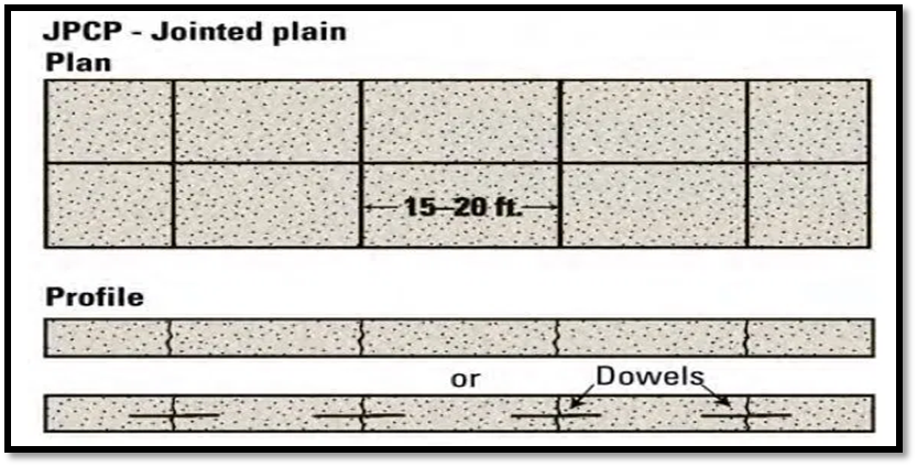
Fig.: Jointed Plain Concrete Pavement
Jointed Reinforced Concrete Pavement:
Although reinforcements do not improve the structural capacity significantly, they can drastically increase the joint spacing to 10 to 30m.
Dowel bars are required for load transfer.
Reinforcement’s help to keep the slab together even after cracks.
The reinforcement, distributed throughout the slab, composes about 0.15 to 0.25 percent of the cross-sectional area and is designed to hold tightly together any transverse cracks that develop in the slab.
It is difficult to ensure that joints are cut where the reinforcement has been discontinued.
This pavement type is not as common as it once was on State highways, but it is used to some extent by municipalities.
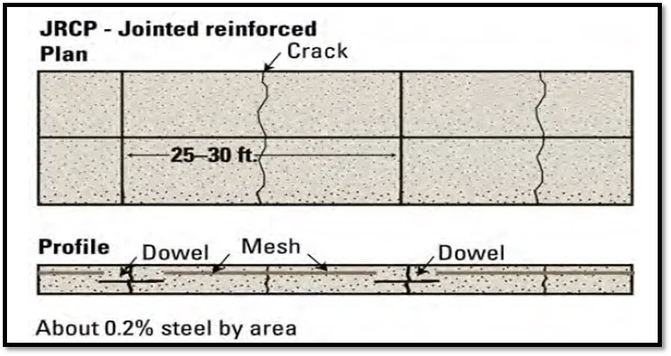
Fig.: Jointed Reinforced Concrete Pavement
Q11) Explain continuous reinforced concrete pavement.
A11) Continuous Reinforced Concrete Pavement:
CRCP designs have no transverse joints, but contain a significant amount of longitudinal reinforcement, typically 0.6 to 0.8 percent of the cross-sectional area.
Transverse reinforcement is often used.
The high content of reinforcement both influences the development of transverse cracks within an acceptable spacing (about 0.9 to 2.5 m apart) and serves to hold cracks tightly together.
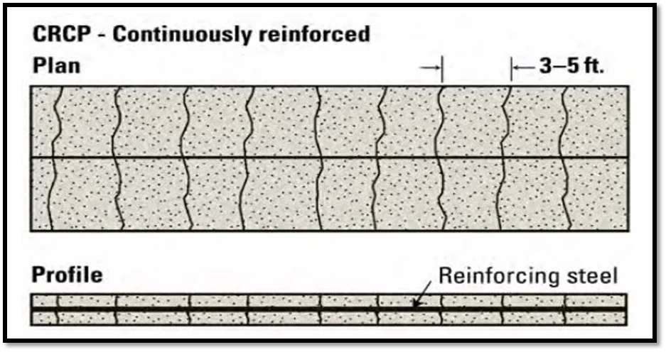
Fig.: Continuous Reinforced Concrete Pavement
Q12) Explain stress in rigid pavement.
A12) Stress in rigid pavement
Notation
Q13) Explain IRC design method in detail.
A13) IRC design method (IRC: 58-2011)