Unit - 5
Design of water tanks
Q1) Explain Design of water tank?
A1)
To fulfill or meet the daily requirement of water by industries society each building of town and cities various types of reinforced cement concrete water tanks are used. The water can be classified based on location and based on shape.
The tank resting on ground and underground tanks have flat bottom slab but elevated tanks have flat bottom of conical bottom.
The water tanks are not only design for strength but also for imperviousness. To design water tanks impervious following points are considered in the design.
- Increase water cement ratio of concrete
- Use of richer concrete mix minimum M20 can be used.
- Give smaller diameter of bars at closer interval
- Proper mixing, good compaction and good curing is required.
- Keep tensile stresses low in conc etc.
The behavior of wall of water tank is more complex. They need sophisticated method of analysis. Use of sophisticated analysis makes the design more economical. However, there are approximate method of analysis commonly used in the design in the approximate method.
- It is assumed that is case of circular tanks bottom 1/3 rd height of 1 m Whichever is greater is predominantly under cantilever action.
- In case of rectangular tanks bottom ¼ height or 1 m whichever is greater is mainly under cantilever action. Rest of the wall is resisting water pressure by forces developed in horizontal directions. Approximate method is always on safer side and hence design is uneconomical. However, it has the following advantages:
- It is simple
- It gives feel of the structural behavior
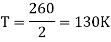
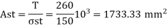
Q2) Design the section of a circular water tank with flexible base and resting on ground. The wall is subjected to a maximum hoop tension of 260 KN Use Fe500 grade of steel and M35 grade of concrete. The limiting design surface crack width may be taken as 0.1 mm
A2)
Given:
Maximum hoop tension: 260 KN
Fe500 
M35 hence
Step 1 Design constant
- Modular ratio
2. NA depth factor
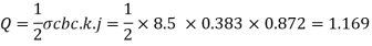
3. Lever arm factor
4. Moment resistance factor
Step 2 Design of tank walls
Since tank is flexible base tanks wall are designed only for hoop action
As the given maximum hoop tension equal to 260 KN
- Design at bottom of wall
S= 110 mm
b. Design of wall at mid height
Hoop tension at mid height

Spacing S= 230 mm
Step 3 Design of base slab
Provide base slab of minimum thickness = 150 mm


Spacing S= 170 mm
Q3) What is Design requirements?
A3)
In water keeping shape a dense impermeable concrete is required therefore, percentage of pleasant and direction aggregates to cement have to be together with to provide excessive exceptional concrete. Concrete blend weaker than M20 isn't always used. The minimal amount of cement within side the concrete blend will be now no longer much less than 30 kN/m 3. The layout of the concrete blend will be such that the consequent concrete is sufficiently impervious. Efficient compaction ideally with the aid of using vibration is essential. The permeability of the very well compacted concrete is depending on water cement ratio. Increase in water cement ratio increases permeability, whilst concrete with low water cement ratio is hard to compact. Other reasons of leakage in concrete are defects together with segregation and honey combing. All joints have to be made water-tight as those are capability re assets of leakage.
Design of liquid keeping shape isn't like normal R.C.C, systems because it calls for that concrete have to now no longer crack and for this reason tensile stresses in concrete have to be inside permissible limits. A bolstered concrete member of liquid keeping shape is designed on the same old concepts ignoring tensile resistance of concrete in bending. Additionally, it has to be ensured that tensile pressure at the liquid keeping face of the equal concrete phase does now no longer exceed the permissible tensile power of concrete as given in desk 1. For calculation purposes the duvet is likewise taken into concrete area.
Cracking can be brought on because of restraint to shrinkage, enlargement and contraction of concrete because of temperature or shrinkage and swelling due to moisture consequences. Such restraint can be as a result of ñ (i) The interplay among reinforcement and urban in the course of shrinkage because of drying. (ii) The boundary situations. (iii) The differential situations winning via the big thickness of huge concrete.
Pdf Machine: A pdf creator that produces exceptional PDF documents with ease! Produce exceptional PDF documents in seconds and maintain the integrity of your unique documents. Compatible across almost all Windows platforms, if you may print from a home windows software you may use pdf Machine. Get yours now! 5 Use of small length bars located properly, results in nearer cracks however of smaller width. The hazard of cracking because of temperature and shrinkage consequences can be minimized with the aid of using restricting the modifications in moisture content material and temperature to which the shape as an entire is subjected. The hazard of cracking also can be minimized with the aid of using lowering the restraint at the free enlargement of the shape with lengthy partitions or slab based at or below floor level, restraint may be minimized with the aid of using the availability of a sliding layer. This may be supplied with the aid of using founding the shape on a flat layer of concrete with interposition of a few fabrics to interrupt the bond and facilitate motion. In case duration of shape is big it has to be subdivided into suitable lengths separated with the aid of using motion joints, in particular wherein sections are modified the motion joints have to be supplied. Where systems must save warm liquids, stresses as a result of difference in temperature among outside and inside of the reservoir have to be taken into account. The coefficient of enlargement because of temperature alternate is taken as eleven x 10 -6 /° C and coefficient of shrinkage can be taken as 450 x 10 -6 for initial shrinkage and two hundred x 10 -6 for drying shrinkage.
Is 3370 (reaffirmed in 2009) is the code of practices used for concrete structure for the storage of liquids i.e., Water tanks was first published in 1965. The code is available in four parts:
IS 3370: 2009 (Part I): General requirement.
IS 3370:2009 (Part II) Reinforced concrete structures
IS 3370 -1967 (Part III): Pre stressed concrete structure
IS 3370 -1967 (Part IV): Design Tables
Limit state method of design is not used in water tanks to avoids leakage problems. IS 456-2000 is silent about permissible stresses in direct tension. Hence IS 3370-2009 is used. The permissible stresses of concrete and steel are shown in table
Q4) Explain Design of tanks on ground?
A4)
These tanks are preferred for large capacities depending upon the connection of wall with base, circular tanks are classified as,
- Circular tanks with flexural base
- Circular tanks with rigid base
Circular tanks can have flexible base or rigid base. In case of flexible joints, the wall is free to move outward when internal water pressure is applied and hence the wall is subjected to hoop force T only.

Where
 = Unit weight of water
H= Height of tank
D= Diameter of circular tank
The reinforcement for hoop stress is to be given in horizontal direction. In vertical direction only minimum steel is to be provided.
In case of rigid joint lower portion is having predominantly cantilever action while upper portion is mainly in hoop tension
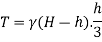
Maximum hoop tension at D
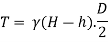
For circular tank h may be taken as H/3 or 1 m whichever is more.
Free board:
In all water tanks a free board of about 200 mm is to be given in other words depth of water tanks is kept 200 mm more than the required depth for the full capacity. However, for the design depth of water is taken as the total depth only since occasionally a stagnant water upon full height may be stored.
Q5) What is Design step of tank?
A5)
Step I
Find Design Constants
Step II
Fixation of dimensions
1) Diameter of tank D
2) Thickness of tank wall(t)
- 150 mm
- 30mm per meter depth +50mm
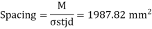
- Tensile stress= T/(b.t+(m-1) Ast
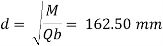
Where T= Hoop Tension = 
Step III
Design of tank wall
Step IV
Design of distribution steel
Step V
Design of base slab
Step VI
Detailing
Q6) Design a circular tank with flexible base for 5 lakh liter capacity. Use M25 Fe 415 Adopt of water excluding free board as 3.5 m. Assume stress in steel as 150 N/mm^2
A6)
Step I Design Constants
Concrete grade M25 and Steel Fe 415
According To IS: 456-2000
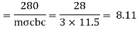
1) Modular ratio(m)
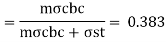
2) N.A depth factor (k)
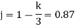
3) Lever arms factor (j)
4) Moment resisting factor
Step II Fixation of dimensions
1) Diameter
Shape of circular with internal diameter D
Total height= 3.5 m
Free board= 200mm
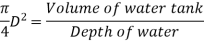
Volume of tank = 5 Lakh liter = 5x10^5x10^3 cm^3= 500m^3
= Area x Depth
Area = 500/3.5 = 142.85 m^2
D= 14.28 m = 15m
Internal diameter of tank= 15m
2) Thickness of tank wall: Thickness of tank wall will be from the following two
- 150 mm thickness of wall
- t = 30 x H+50= whichever is more
t= 30 x 3.5 +50= 155mm
c. Let us adopt t= 200mm (thickness is checked for limit tensile stress in concrete to 1.2 MPa)
Step III
Design of water tank walls: Since tank is with flexible base it will be designed as circular system cylinder subjected to water pressure
- Design for bottom part of wall: Consider the bottom =3.5/3 = 1.16 m
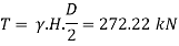
Hoop tension at bottom
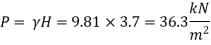
Maximum pressure intensity corresponding to the 1 m height of wall
Ast calculation
Permissible stress= 150 MPa
Ast required= T/permissible stress= (272.22 x 10^3)/150 = 1814.3 mm^2
Provides t= 200 mm

So, provide Ast required
Let us adopt  = 16 =
Spacing S= 1000ast/Ast= 1000 x (201/1814.8) = 110.78mm
So, provide  16 @110 mm c/c along the wall upto 1 m@ 220 mm c/c. This reinforcement is applicable from B to D.
2. Design for middle part of wall
- Hoop tension at middle part
Consider 1.16 m in middle part of wall
i.e., F to D
Hoop tension at D can be found out
Similarly, P= 9.81 x (3.7 – 1.16) = 24.91 kN/m^2
Hoop tension at D= 24.91 x 15 / 2 = 186.88 kN
Consider same tension for 1.16 m above D i.e. From D to F
b. Ast calculation
Ast = To/permissible stress = 186.88 x 10^3 /150 = 1245.86 mm^2
Ast min. = 600 mm^2
Now Ast required > Ast min
Hence provide Ast required
Provide  16 mm, ast =
Spacing
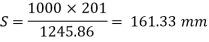
Provide  16 mm@160 mm c/c divide this reinforcement in two parts. i.e Provide
  16 mm@ 320 mm near and away from water face for F to D 1.16 m height of wall
Q7) Design of top 1.36 mm height of wall: for top 1.36 m height of wall maximum hoop tension will be at point F
A7)
Hoop tension of F = 72.10 kN
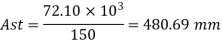
But Ast min = 600 mm^2
Ast required < Ast min
Provide  10 mm
10 mm
Spacing
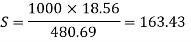
Provide 
Divide the reinforcement in two parts
S= 2x 160 = 320 mm c/c
Step: Distribution Steel
Provide 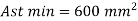
Provide  10 mm@320 mm c/c
Step:
Provide base slab of minimum thickness = 150mm
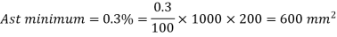
Ast = Ast min = 0.3 % Ag = 0.3 /100 x 1000 x 200= 600 m62
Provide  10 mm
10 mm
Ast = 78.54 mm^2 @120mm c/c
Q8) Design a square water tank resting on ground for a capacity of 75 of liter. Use M30 grade of concrete and steel of grade Fe500 Sketch the details of reinforcement
A8)
Step 1 Fixation of dimensions
- Volume of tank = 75000 lit = 75 m^3
Consider water tank of size 5mx5mx3m
2. Thickness of wall
This will not be less than
- 150 mm
- 30 mm per m depth +50 mm = 30 x3+50 = 140 mm
- 60 mm per meter length of the side = 60 x 5 = 300 mm
Provide thickness of 300 mm
Effective span of slab = 5+0.3 = 5.3 m
Step 2 Design of wall
Consider a level 1 meter above the floor water pressure intensity of this level
= 9810 x2 = 1920 N/m^2
Bending moment per meter height at this level at corners
Pull in the wall per meter height at this level
T= 19620 x5/2 = 49050 N
1) Design of corner section
Providing a cover of 25 mm and using 18 mm bar effective depth
300-25-18/2 = 266 mm
Effect bending moment at corners

Since BM produce tension near the water face the stresses and the design coefficient to be adopted are
T = 150 N/mm^2
C= 10 N/mm^2
M^2 = 9.33


Steel for bending moment
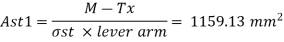
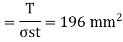
Settle for pull Ast2 = Pull/ = 327 mm^2
Total steel required
Ast1+Ast2 = 1159.13+327 = 1487 mm^2
Spacing of 18 mm bars
S= 170 mm
Provide 18 mm  @ 170 mm c/c
3. Design of mid span section
Section moment = 34445 NM
Pull= 49050 N
Effect bending moment M-Tx
= 3445 x 1000 -49050 (266-150) = 28755200 Nmm
Since this bending moment produce tension away from the water face the stresses and the design coefficient to be adopted are
t = 190 N/mm^2
c = 10 N/mm^2
M= 9.33
a = 0.87 d
Steel for BM

4. Design of the bottom 1 meter height of wall
This will be designed as a cantilever 1 meter height and subject to a triangular load ranging from zero at the top to the cantilever to 980x3 = 29430 N/m^2 at the bottom
Maximum pressure force on this cantilever
= ½ x 29430 x 1 = 14715 or acting at 1/3 m from base
Bm for the cantilever = 14175 x 1/3 = 4905 Nm
Provide 10 mm fi vertical bars @160 mm c/c near each face. The vertical bars near face are enough to result cantilever moment
Q9) Design a rectangular water tank resting on ground. The tank dimensions are 7 m x 3m x 3m high use M 30 and Fe 500 grade material.
A9)
Step 1 Design of wall
L= 7 m
D = 3 m
L/d = 7/3 = 2.33 >2 m
Long wall is designed as vertical cantilever tension in the long wall
Tension per meter height of long wall


T = 9800(3-1)/2 x 3 = 29400 N
Maximum bending moment at the base of wall

Step 2 Design constants
Modular ratio


Depth required
Provide total depth as 210 mm and 40 mm as effective cover d = 210-40=170 mm
Area of steel required


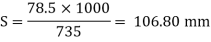
Hence provide 10 mm diameter bars
At 106.80 x 2 = 213.60 = 220 mm c/c on both faces.
Q10) Explain Underground and elevated water tanks?
A10)
Compared with different ground storage structures, underground tanks are usually small, with volumes ranging 20 to 150 m3. They permit irrigation of small plots of land and livestock watering and are appropriate to smallholder irrigation as character farm storages. A most important limitation is the dearth of ok information at village stage to layout and assemble underground tanks. Also, the layout and production faces extra demanding situations of functionality, safety, water abstraction and opportunity of failure compared to floor tanks. However, underground tanks proportion a whole lot of the functions of floor tanks concerning production substances and methods. Water harvesting from conventional huts in the case of grass thatched or different conventional homes e.g., “Mayetta”, in which roof catchment with floor tank is not feasible, underground tanks can be used to supply domestic water.
For grass-thatched homes, round trenches can be dug and placed to receive runoff directly below the roof eves and trench gutters dug around 3 hemispherical conventional homes. The miter drains from the ditch acts as a gutter and need to be placed at the facet or behind the residence to be accessible. The miter drains deliver runoff into an underground tank.
There are many types of underground tank, categorized according to shape, size, capacity, lining material, creation and utilization. The maximum not un usual place kinds of tanks encompass.
Cisterns: A cistern is a small underground reservoir of approximately 10 to 500 m3 capacity. The time period is from time to time synonymous with underground tank. Cisterns are indigenous water harvesting structures commonly observed within side the Middle East and different dry areas. They are usually used for human and livestock water consumption, and are mostly located at or near homesteads.
In many areas, they are dug into the rock, or they could be constructed as underground tanks lined with concrete. In this system, runoff water is accrued from catchments including roofs, domestic compounds, rocky surfaces, roads or open areas. Stilling basins are from time to time had to lessen sediment entry. Since the water is saved beneath ground. A lifting device, e.g., pump, bucket and twine are used to deliver water to the surface for use. Other than domestic use, cisterns are also used for irrigation of small gardens. Cisterns require very little area above ground, and as a result are unobtrusive, that's a protection feature. The main problems associated with this system encompass the cost of creation, the cistern’s constrained capacity, and inflows of sediments and pollution from the catchment.
Rectangular coated tanks: One of the simpler approaches of building underground tanks takes the form of a rectangle or square. However, maximum square tanks have a trapezoidal profile in volume. This form accords good garage with clean layout and creation features, as developers use directly lines. The tank can be coated with geo-membrane plastics, concrete, bricks, and other water resistant material. Lined underground tanks have the benefit of applicability on nearly any soil type.
The layout additionally makes it simpler to roof or cowl the tank with galvanized iron sheets, grass, polythene, wood or other material. The tank is particularly popular for runoff harvesting for agricultural purposes, mainly supplemental irrigation of small plots.


