Unit - 2
Bearing Capacity and Shallow Foundation
Q1) What is Bearing Capacity?
A1)
- Bearing capability of foundation is that the most average intensity of applied pressure that a finite loaded space will carry before underlying material fails in shear.
- The criteria for the determination of bearing capacity of a foundation are supported the wants for the steadiness of the muse. These are declared as follows:
- Shear failure of the foundation or bearing capacity failure, because it is usually called, shall not occur. (This is related to plastic flow of the soil material beneath the foundation, and lateral expulsion of the soil from underneath the footing of the foundation); and,
- The probable settlements, differential as well as total, of the muse should be restricted to safe, tolerable or acceptable magnitudes. In different words, the anticipated settlement beneath the applied pressure on the foundation mustn't be harmful to the steadiness of the structure.
Q2) Explain the terms related to bearing Capacity?
A2)
Various terms involving bearing capacity are as follows:
- Ultimate bearing capacity (UBC),
- Net bearing capacity (NBC),
- Safe Bearing capacity (SBC),
- Unit sol pressure,
- Allowable soil pressure,
Ultimate bearing capacity (UBC)
It is defined as the minimum gross pressure intensity at the bottom of the muse at that the soil fails in shear.
Net bearing capacity (NBC),
In the ultimate B.C. (UBC) - surcharge result
q u n = q u –q
q u n = c N C + q (N q -1) + 0.5  B N q
B N q
Safe Bearing capacity (SBC),
Foundation ought to be designed for pressure Intensity a lot of smaller than the last word Bearing capability (UBC) to produce an appropriate issue of safety. F r
SBC for footing placed at depth D r
q F = q u n /F s+  D f
D f
If surcharge q =  D f isn't effective (if removed thanks to erosion).
q f = q u n / F s
Foundation pressure are generally surface intensities or net pressure for foundation below the ground surface appropriate overburden surcharge must be considered as additional pressure if it is known to be permanent
Safe soil pressure, q f = q u n /F s +  D f
D f
Unit soil pressure
It is the applied pressure that produce an average unit settlement of the foundation known as tolerable settlement
Allowable soil pressure
It is the maximum net intensity of loading that can be imposed on the soil with no possibility of shear failure or the possibility of excessive settlement
Hence it is the smaller of the net safe bearing capacity and safe bearing pressure
Q3) Explain Rankine’s analysis?
A3)
Rankine attempted to determine ultimate bearing capacity of the soil by considering the equilibrium of two elements of the soil, one below the footing and another outside the footing adjacent to the first one.
Following is the equation for ultimate bearing capacity as per Rankine’s theory for cohesionless soil:


Where Kp is the Rankine’s coefficient of passive earth pressure.


Where Ka is the Rankine’s coefficient of passive earth pressure.
Q4) Explain General shear failure?
A4)
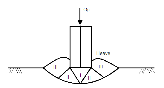
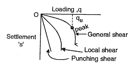
Fig.: General shear failure
Dense sand, stiff and hard clays
Io >85, N > 30,  > 36
> 36
Tri axial test shows pronounced peak and failure at small strain
Base failure occurs at very small vertical strain accompanied by large lateral strain with surface heave
Sinking of base less than 7% base width
Failure zone is well defined
In load settlement curve, failure load is well defined and peak load is the ultimate load
Q5) Explain Local shear failure?
A5)
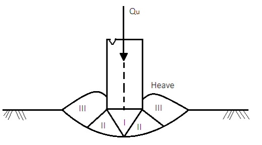
Fig.: Local shear failure
Loose and medium sands medium to soft clay
Io = 15 - 65, N = 10 -30,  < 30
< 30
No peak and failure at large strains
It occurs at large vertical strain and very small lateral strain with no surface heave
Sinking may range from 15 - 20 % base width
Failure zone is difficult to define
From land settlement graph, first indication of failure is large deformation in soil in early stage of loading which is difficult to distinguish during an incremental load test.
Q6) Explain Punching Shear Failure?
A6)
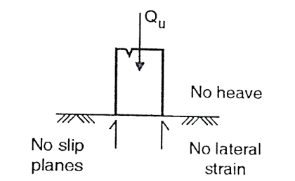
Fig.: Punching Shear Failure
Very loose and soft saturated clay.
Io < 15, N < 10
Failure with heavy compression.
No lateral strain only large vertical strain.
Sinking may ranges from > 20% base width.
Failure is by sinking and indicate no slip planes.
Load settlement curves indicates failure at very small loads and excessive settlement.
Q7) Explain Terzaghi’s analysis?
A7)
Terzaghi analysis although not terribly rigorous permits USA to work out final bearing capability of shallow strip footing with rough base.
Assumptions concerned within the Terzaghi theory:
- The footing is rough (This is common actual field condition)
- It is shallow i.e., its depth below the surface isn't greater than the dimension.
- The shear strength of the soil between the bottom level and also the bottom footing is neglected and this soil is taken into account solely as surcharge imposing uniform pressure on the horizontal plane at foundation level.
- General shear failure is assumed which the degree of the soil before and when failure is unchanged.
- A wedge of soil forthwith below the bottom in state of elastic equilibrium LE. It's half and parcel of the footing.
- Passive pressure Pp consists of 3 parts which might be calculated on an individual basis and intercalary though the essential surfaces for these parts aren't identical.
- Failure zones don't extend on top of the horizontal plane through the bottom of the footing i.e., the shear resistance of soil on top of the bottom is neglected and also the impact of soil round the footing is taken into account akin to a surcharge q=YD.
- The footing is continuous. This makes the matter a two dimensional one. For isolated footings, however, Terzaghi future counseled some correction factors to be applied to tie bearing capability values figured out for continuous footing.
Based on these assumptions, the last word bearing capability ratio is figured out as mentioned below:
Derivation of equation for bearing capacity
On application of load intensity alphabetic character on the footing, the soil wedge bedrock tends to maneuver downward with lateral displacement of zone three and a couple of. But this lateral displacement is resisted by the forces functioning on the planes CB and CA
The forces functioning on these planes
- Cohesion c acting on the surfaces CB and CA
- The resultant of passive pressure Pp. Creating associate angle o with the traditional to the surfaces CB and CA. Now, when the surface AC associated BC build an angle o with the horizontal, then the passive pressure P would act vertically upward. At failure, the downward and therefore the upward forces on the wedge ACB of unit length should be equal. Additionally, during this position, the building load alphabetic character can represent the final word bearing capability of the soil, and therefore may be substituted by q u r. Hence, the downward forces per m run.
- q u l t
- The load of the wedge ACB =1/2 B (height of
 )
) = ½ B B/2
 - Tan
 = ¼
= ¼  B2 tan
The upward forces are: (1) the passive pressures Pp on every of the surface AC and BC i.e., 2 Pp: and (2) the upward element of cohesion is, acting on CA and CB
= 2 CA c sin  = 2 ((B/2)/ Cos
 ) c sin
  = B c tan
Equating downward and upward forces, we get
q u l t. B + ¼  B2 Tan
  = 2 Pp + B .c tan
q u l t B = 2 Pp + b c tan  - ¼
- ¼  B2 tan
The total passive pressure Pp encompass the subsequent
- Passive pressure because of the load of the soil shear zone ACFG. It depends upon
 and therefore is written as Pp .it acts joined third distance from C on CA or CB
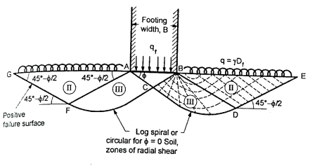
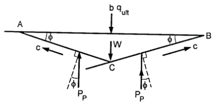
Fig.: Failure under a strip footing supported on the ground surface (footing base rough as per Terzaghi)
- Passive pressure due to soil cohesion, acting at midpoint of CA or CH. It depends upon c, and thence is written as Pp(c)
- Passive pressure attributable to surcharge (q), working at middle purpose of CA or CB. Since it depends on g. Allow us to write it as Pp(q)
- Equation becomes
q u l t B = 2 [Pp( ) + Pp(c) + Pp(q)] + B c tan
  - ¼
- ¼  B2 tan
Since the term (2 Pp( ) – ¼
) – ¼  B2 tan
  ) depends on
Let us express it as N .
. B2
B2
2 Pp ( ) – ¼
) – ¼  B2 tan
  = (N
= (N )
)  B2/2
B2/2
2 P p(c) + B c tan = N c B c
2 P p(q) = N q B  D f
D f
Where N , N c and N q are dimensionless
 bearing capability factors, counting on The Equation then becomes:
C= cohesion
D = depth of foundation
 = unit weight of soil
- Terzaghi gave the subsequent expression for the bearing capability face
N q =  2 / [2 Cos 2 (45+
  /2)]
/2)]
N c = (N q-1) cot 
And
N  = tan
= tan  /2 [(K p y /cos2
 )-1]
)-1]
K p  = Passive earth pressure constant depend upon
- The values of N
 at
at  = 0, 34, 45, are 0, 35, 297.5
Q8) What is Brinch Hansen Analysis?
A8)
It takes under consideration the. Influence of depth dc", form shape of base S and inclination of loading.
UBC is expressed within the general kind as
q u = c N c s c d c I c + q N q S q d q I q + 0.5  B N
B N s
s  d
d  I
I 
And is in shut agreement with expected result for cohesive soil
Factors N c N q N  values area unit somewhat smaller than corresponding Terzaghi values.
Increase exhaustive shows important increase in bearing capability N issue
Here N q = tan 2 [(45 + )] e
)] e  tan
tan 
N c = (N q -1) cot 
N  = 1.8 (N q-1) tan
Vesic Analysis: it's just like Hansen's equation only there's slight distinction in worth of N, and variation on some Hansen's inclination, form and depth factors.
Vesic's formula for N  states
N  = 2 (N c +1) tan
Hansen's and Vesic's bearing capability factors area unit satisfactory for non-cohesive likewise as cohesive soils.
 | N c | N q | N y | N y (versis) |
0 | 5.14 | 1 | 0.0 | - |
5 | 6.48 | 1.57 | 0.09 | 0.45 |
10 | 8.34 | 2.47 | 0.47 | 1.22 |
15 | 10.97 | 3.94 | 1.42 | 2.65 |
20 | 14.83 | 6.4 | 3.54 | 5.39 |
25 | 20.72 | 10.66 | 8.11 | 10.88 |
30 | 30.14 | 18.4 | 18.08 | 22.4 |
35 | 46.13 | 33.29 | 40.69 | 48.03 |
40 | 75.32 | 64.18 | 95.41 | 109.41 |
45 | 133.89 | 134.85 | 240.85 | 271.76 |
50 | 266.89 | 318.96 | 681.84 | 762.89 |
B = form issue to account for impact of form of foundation in developing failure surface.
d = Depth issue to account for embedment depth and therefore the further cut resistance within the prime soil
i = Inclination issue to account for each horizontal and vertical parts of foundation hundreds.
S FACTOR:
Sc | Sq | Sf | ||
A | Strips | 1 | 1 | 1 |
B | Rectangular | 1 + 0.2 B/L | 1 + 0.2 B/L | 1- 0.4 B/L |
C | Square | 1.3 | 1.2 | 0.8 |
D | Circle | 1.3 | 1.2 | 0.6 |
d FACTOR: (for B Df)
Df)
d c = 1+ 0.2 ∆f/B (√N Q)
d q = 1 for  < 10
< 10
d q = 1+ 0.1 ∆f/B (√NQ)
Where
N Q = tan² (45+  /2)
/2)
I -FACTOR:
I c = (1-  /
/ )2
)2
Q9) What is Meyerhof’s analysis?
A9)
- He extended the analysis of plastic equilibrium of a surface footing to shallow and deep foundations.
- It yields bearing capability of strip footing on a rough base.
It differs from Terzaghi's equation as
- It involves the lateral stress constant that ranges between the active and passive values, betting on unit weight, angle of friction and deformation condition
- The shear zone extends higher than the bottom level Angle of wedge
 is bigger than
 =45+
=45+  /2
/2
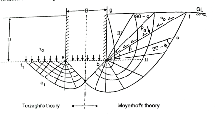
Fig.: Shallow Foundation
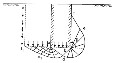
Fig.: Deep foundation
- In Meyerhof's analysis, a b d is that the elastic zone, b d e is that the radial shear zone and b e f g is that the zone of mixed shear within which she varies between radial and plane shear relying for the most part upon the depth and roughness of foundation.
- The plastic equilibrium in these zones will be established from the boundary conditions ranging from the muse shaft.
- To alter the analysis, Meyerhof's introduced a parameter 'B' the angle to define line b to f, wherever the assumed boundary failure slip line intersects the soil surface,
- The resultant roll in the wedge of soil b f g is painted by the conventional and tangential stresses P o and So on bf.
- Plane bf is termed because the equivalent free surface and P o and so are eliminated because the equivalent free surface stresses.
- Angle B will increase with depth, and becomes 90° for deep foundation.
- Though Terzaghi analysis differs with Otto Fritz Meyerhof, Terzaghi's general equation will be used with Meyerhof's bearing capability factors.
- Bearing capability values obtained are on
 the point of experimental values and lie between general shear and native shear values of Terzaghi equation for shallow foundation (D, s B), however up to abundant higher for deep foundations
 - Hence Meyerhof recommended the employment of reduced price of zero. When tan
 = 0.85 tan
  for deep foundation
Q10) Explain Vesic’s Bearing Capacity Equation?
A10)
In Terzaghi's analysis value of Nc, is taken as 5.7; and does not take into account effect of depth of footing. Skempton carried out exhaustive research on cohesive soils taking into account depth D, length L and width B of footing and gave his findings as under:

Where D/B  2.5;
2.5;
c = cohesion.

Where L = B = square or circular footing and D=0

=7.2c if D=B
=9.c when D/B and footing is square or rectangular
Enclosed Fig. Shows values of N, for various D/B ratios for rectangular and strip footing as recommended by Skempton.
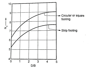
Fig.: Skempton value for 
Q11) What is the effect of water table on Bearing capacity?
A11)
When the water table is above the base of the footing, the submerged weight  should be used for the soil below the water table. When the water table is located somewhat below the base of footing a suitable reduction factor should be used with the last term i.e.,
  . For any position of the water table, B.C. Can be found out using following equation:

Where Rw1 and Rw2 are the reduction factors for water table and can be computed as shown in Fig.
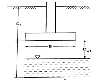
Fig.: GWTL below base of footing
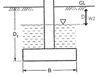
Fig.: GWTL above base of footing
Q12) Explain IS code method for computing bearing capacity?
A12)
The ultimate net bearing capacity of strip footing is given by the following equation
For the case of general shear failure:
q n f = c N c + q (N q -1) + 1/2  B N
B N 
For the case of local shear failure:
q n f =2/3 c N c’ + q (N q’ -1) + 1/2  B N
B N 
Where
q = effective surcharge at the base level of foundation
N c, N q, N f = bearing capacity factors
These factors are computed from the following equation:


=2(
Q13) Explain Plate load test and its limitations?
A13)
- Instead of relying on the values of safe bearing capacity given in code of practice, many times plate bearing test is carried out at work site as follows:
- At first, pit is excavated of dimensions which should be as shown in Fig. And levelled upto depth at which test is to be carried out.
- A thin layer of sand or plaster of Paris is spread over it. A thick square plate of size 30 to 75 cm is placed at the centre below the bottom of test pit.
- Hydraulic jack is placed over these plates and a proving ring is placed underneath steel truss and over hydraulic jacks.
- By applying pressure through hydraulic jack, effort is made to lift the load on main steel girder. This causes compression of proving ring.
- Compression of proving ring is proportional to the load applied. Compression of ring is noted by a dial gauge. Thus, indirectly the dial gauge will indicate the load applied.
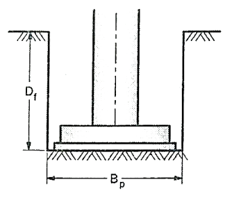
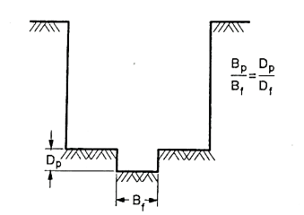
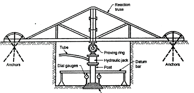
Fig.: Plate bearing test using reaction frame
- To know the settlement / sinking of plate, three dial gauges @120° are placed over the steel plates. The dial gauges themselves are supported by datum bar, which is far away from the plates.
- M. S. Plate of 2.5 cm thickness of size as under is provided:
Clayey, sandy and silty soils 60 cm x 60 cm.
Gravelly and dense sandy soils 30 cm x 30 cm.
- At the start, seating load of 70g/cm² (7 kN/m²) is applied and released.
- Then load in increments of 200 kg or 1/5th of approximate load bearing capacity, whichever is less is applied, till about 1.5 times the expected ultimate bearing capacity or ultimate load is reached.
- Sometimes it becomes difficult to arrange for kentledge. As an alternative, as shown in Fig. Reaction frame consisting of steel truss is anchored down suitably by connecting it to anchor pile or by driving anchor rods.
- The steel truss thus, offers necessary reaction. It must be ensured that, the reaction offered by the steel truss should be far in excess of the maximum load that will be applied on the plate.
- A heavy steel proving ring is placed below deep and strong steel beams and over these beams’ heavy loads in the form of steel joists or cement bags are placed. By trying to lift the load on beam, pressure is exerted over steel plates.
- Then load, settlement graph as shown in Fig. Is plotted, from which ultimate bearing capacity and hence safe bearing capacity can be determined.
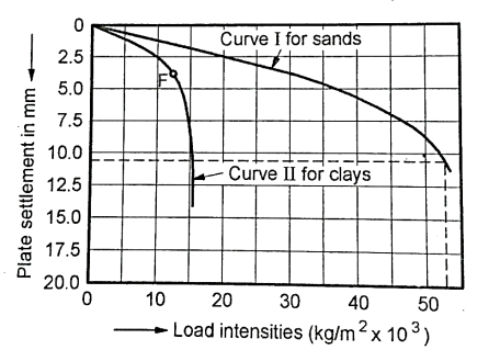
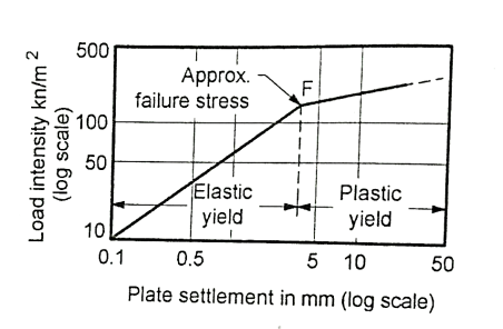
- Fig. Shows typical load-settlement curves for different soil conditions. Terzaghi and Peck (1948) have recommended that the settlement of a footing on a cohesionless (that is, granular) soil can be extrapolated from the settlement experienced by a test plate at the same load intensity, by the following equation:

Where, Sf = Settlement of a foundation of width B, (cm)
Sp = Settlement of the test plate of width B, (cm) at the same load intensity as on the foundation
- A plate load test is of short duration. The settlement measured is only the immediate settlement.
- In granular soils, immediate settlement can be taken as the total settlement, while in cohesive soils, consolidation settlement, which constitutes most part of the total settlement, cannot be predicted through this test.
- Hence the plate load test is not of much relevance in clayey soils for which the settlement criterion is very important in the determination of the allowable bearing pressure of a foundation.
- Thus, the equation,

- If the load test is carried out above the natural water table, the settlement computed from the load-settlement curve will have to be corrected if there is a likelihood of a rise in water table at a future date, leading to submergence of the soil below the foundation.
- The actual settlement is calculated thus:
Actual settlement = 
Limitations of Plate Bearing Test:
- Test is carried on a small area and the results are used for larger area. Ultimate bearing capacity in respect of clayey strata, remains unaffected, whether the test is carried on small area or large area. However, in case of cohesionless soils, bearing capacity increases with size of footing.
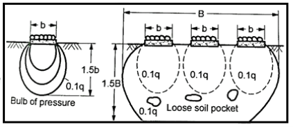
- If q is the intensity of loading on plate, then, at depth equal to twice the width of plate (i.e., 2 B.) stress intensity reduces to only 0.1 q which is negligible. Thus, with this test, soil upto a depth of twice the width of steel plate is tested.
But in practice, B, the width of footing is far more than B. Hence, if loose weak soil pockets are present within a depth of 2 B, then results obtained from the plate bearing test will not hold good.
- With rise in water table, bearing capacity reduces. This aspect needs consideration while finalizing bearing capacity, especially of non-cohesive soils. As per I.S. Water table should be brought artificially at the depth,
- At which test is to be carried out by consolidating and flooding the test pit, if water table is below the test level.
- However, if water table level is above the test level, it should be lowered upto test level, by pumping out water.
- It is difficult to carry out test at great depths.
- The results of test carried on small square plate cannot be used for continuous footing.
- Settlement in respect of cohesive soils take lot of time, as such, ultimate settlement of cohesive soils cannot be determined in short period. Test carried for short period does not give correct idea of bearing capacity.
- In case of sandy and non-cohesive soils, the bearing capacity increases with increase in the size of plate footing, whereas in case of clayey soils, bearing capacity of large foundation is the same on that of test plate. Thus, the results depend upon the size of plate and type of soil strata.
Q14) Explain Standard penetration test?
A14)
- The tests essentially consist in diving a split spoon sampler of 50 mm outside diameter into the soil
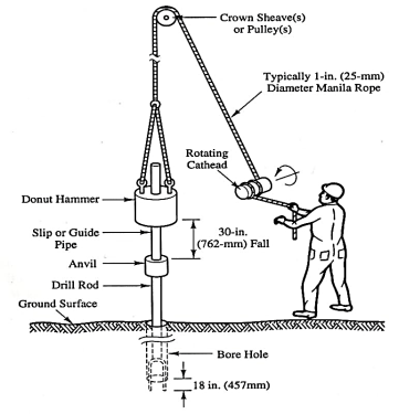
- The sample should to be driven at rock bottom of borehole that is cased in a very pipe is forced into the bore hole and take a look at conducted at rock bottom of the bore hole.
- In case the strata is stiff like gravels and sandy mallet, a solid cone like 60° shoe is fitted to the sampler. The sampler is to be hooked up to the drill rods and driven by blows of a hammer. The hammer typically
- The sampler is to be hooked up to the drill rods and driven by blows of a hammer. The hammer typically weighs sixty-five weight unit with a free fall of 750 mm. Typically thirty blows per minute are given.
- The sampler is at first driven a distance of one hundred fifty mm below very cheap of bore hole and so an additional distance of three hundred mm.
- The number of blows needed to drive this distance is thought as customary penetration price N.
- The number of blows needed to result the primary one hundred fifty mm of penetration, known as the seating drive, is forgotten
- The split-spoon sampler is then withdrawn and it detached from the drill rods. The split-barrel is disconnected from the cutting shoe and also the coupling. The soil sample collected within the split barrel is rigorously collected on preserve the natural wet content and transported to the laboratory for tests. Sometimes, a skinny liner is inserted inside the split-barrel in order that at the tip of the S P T, the liner containing the soil sample is scaled with liquefies wax at each its ends before it's got rid of to the laboratory
Then take a look at is halted If-
a) 50 blows area unit needed for any a hundred and fifty metric linear unit penetration
b) one hundred blows area unit needed for three hundred penetration.
c) 10 sequent blows turn out no advance and is termed as refusal.
The following precautions ought to be taken whereas closing the take a look at
a) The split spoon sampler should be in condition and the cutting shoe should be free from wear tear.
b) The drop press should be of the correct weight and the fall ought to be free, resistance.
c) Very cheap of the borehole should be properly clean before the take a look at is administrated. Otherwise, the take a look at gets administrated within the loose, disturbed soil and not within the undisturbed soil.
d) Once a casing is employed in borehole, it ought to be ensured that the casing is driven simply wanting level at that the S P T is to be administrated. Otherwise, the take a look at gets administrated in a very soil of very cheap of the casing
- S P T is extensively used as a result of the take a look at is straightforward and economical. It is the sole take a look at that has representative soil samples each for visual scrutiny for natural wet content and classification tests within the laboratory.
- Design charts for shallow foundations resting on cohesion less soils are developed.
Limitations of SPT:
- As SPT is subject to several errors, S P T price isn't terribly reliable.
- 2 In granular soils, correlation between S P T and internal friction angle is incredibly poor.
- Determination of allowable bearing pressure from N values isn't correct.
- S P T price isn't acceptable for determinant the bearing pressure in fine-grained cohesive soils,
- Corrections for overburden and impact square measure to be applied to record N values for correlation with soil properties
Applications of SPT:
- SPT is appropriate for each cohesive and non-cohesive soil variety of SPT is extensively used as a result of the take a look at is easy and comparatively economical.
- It is the sole take a look at that gives representative soil samples each for visual scrutiny within the field and for natural wet content and therefore the classification tests within the laboratory
- This take a look at is employed to work out the density index of sandy soils and consistency of cohesive soils. Variety of tried-and-true correlations square measure out there between N price and soil parameters each for cohesive and non-cohesive soils.
Q15) What is spread footing?
A15)
- It is the foremost common variety of shallow foundation want to transmit load of wall or isolated column.
- The bottom of wall of column is enlarged or unfold to distribute load over an outsized space
- To cut back intensity of load unfold footing doesn't directly rest on soil. Usually, regarding fifteen to thirty cm thick lean concrete of combine (1:4:8) known as foundation concrete is initial laid, as a base course to hide little pockets in foundation and to supply level surface for giving birth spread footing.
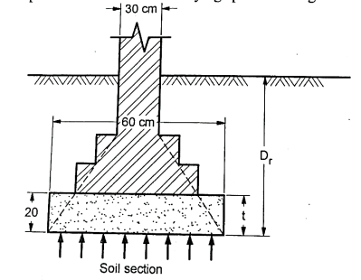
Fig.: Spread footing
- Over this foundation concrete, unfold footing rests. If load of wall footing is high and if their chance of differential settlement, then rather than providing plain foundation concrete, by providing steel reinforcement
- If projection of footing on the far side wall is excessive, the footing could crack thanks to soil reaction within the cantilever portion. Hence, stepped foundation is provided.
- If thickness "t" of footing is a smaller amount, the wall could clock in the footing.
- Depth of foundation (D) ought to be adequate offer necessary safe bearing capability. Minimum depth of foundation of ninety cm is provided
Q16) What is Combined and strap footing?
A16)
Strap footing:
It includes remoted footings related with a structural strap or a lever, as proven in discern below.
The strap connects the footing such that they behave as one unit. The strap truly acts as a connecting beam.
A strap footing is extra most cost-efficient than a blended footing while the allowable soil strain is surprisingly excessive and distance among the columns is large.
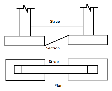
Fig.: Strap footing
Combined Footing:
It helps columns as proven in parent below. It is used while the 2 columns are so near every different that their person footings could overlap.
A mixed footing is likewise supplied while the assets line is so near one column that a range footing could be eccentrically loaded while saved absolutely in the assets line.
By combining it with that of an indoors column, the burden is flippantly distributed. A integrate footing can be square or trapezoidal in plan.
Trapezoidal footing is supplied while the burden on one of the column is bigger than the opposite column.
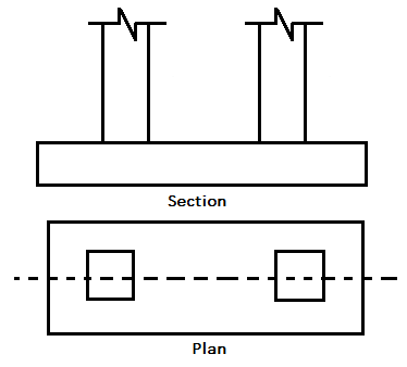
Fig.: Combined Footing
Q17) What is Mat or Raft footing?
A17)
When the under soil is weak or has low bearing capability and column hundreds as significant, mat foundation is provided to transfer the column lands to the underlying soil. Mat foundation or foundation may be a thick ferroconcrete block supporting variety of columns and transmission the masses to the soil.
Types of mat foundation:
- Flat plate met
- Plate thickened under column
- Plate with pedestal
- Piled raft
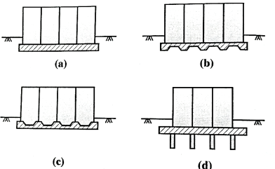
Fig.: Types of mat foundation
(a) Flat plate mat
It is appropriate for fewer compressible soil and comparatively lightweight hundreds with nearer and uniform column spacing
(b) Pate thickened below columns
It is appropriate heavily loaded columns and provides safety from diagonal shear and negative moments
(c) Plate with pedestal
Pedestals square measure provided at base of columns higher than slab associated serve same purpose as kind (b)
(d) Piled raft
When soil is incredibly compressible and geological formation is high, this raft reduces the settlement and might management buoyancy.
Q18) The results of two plate load tests performed on a given location with two circular plates are given below. (i) Dia. = 750 mm, S = 15 mm, Q = 150 kN. (ii) Dia. = 300 mm, S = 15 mm, Q = 50 kN. Determine the load on a circulation footing of 1.2 m diameter that will cause a settlement of 15 mm.
A18)
Given: Q₁ = 150 kN, Q₂ = 50 kN Q₁ = 750 mm = 0.75 m, Q₂ = 300 m
By Housel's formula, Q = Aa+ Pp
For plates,
150 = (0.75)³a + ( x 0.75) p
50 =  (0.3)²a + (
 x 0.3) p
Solving Equation (1) and Equation (ii), a = 94.31 and p=45.98
For footing. Q =  (1.2)2 a + (
 × 1.2) p
Q =  (1.2)2 94.31 + (
 × 1.2) 45.98
Q = 280 kN
Q19) A circular footing is resting on a stiff saturated clay with qu = 250 kN/m. The depth of foundation is 2m. Determine the diameter of the footing if the column load is 600KN. Assume a factor of safety as 2.5. The bulk unit weight of soil is 20kN/m²
A19)
Given: quc = 250 kN/m²,  = 20 kN/m™,
Q = 600 kN, D, = 2m, FS = 2.5
C= quc /2 =250/2 = = 125 kN/m²
By Terzaghi's theory qult= 1.3 cNc + DfNq+0.3
For cohesive soil, N = 5.7, Nq = 1, Nr= 0


=
D=1.36m=1.4m
Q20) A square footing, 1.8m x 1.8m, is placed over loose sand of density 16kN/m and at a depth of 0.8m. The angle of shearing resistance is 30°. Take Nc=30.14, Nq=18.40 and N = 15.10. Determine the total load that can be carried by the footing.
A20)
Given: D, =0.8, B = 1.8,  = 16 kN/m²
 = 30°, Nc= 30.14, Nq = 18.4, N
 = 15.1

= 1.3x0+ 16x0.8 x 18.4+0.4x 16 x 1.8 x 15.10
qult = 409.47 kN/m²
Q21) Compute the safe bearing capacity of square footing 1.5 mx 1.5 m located at a depth of 1.0 m below the ground level in a sandy soil of average density 20 kN/m3,  = 20°, Nc= 17.7, Nq= 7.4 and N
 = 5.0. Assume factor of safety = 3.0 and water table is very deep (Terzaghi analysis).
A21)
Given: 20 kN/m3, B = 1.5 m, Df= 1 m,
To find: qsafe=?
Water table being very deep, Rw1 = Rw2=1

=0+20


Q22) Two load tests were conducted at a site one with a 0.5m square test plate and the other with a 1.0m square fest plate. For a settlement of 25mm, the loads were found to be 60 kN and 180 kN, respectively in the two tests. Determine the allowable bearing pressure of the sand and the load which a square footing. 2m x 2m, can carry with the settlement not exceeding 25 mm.
A22)
By Housel's formula,
Q = Aa + Pp
60 = (0.5)2a +(4x0.5) p…. (1)
180 = (1)2a+(4x 1) p ... (2)
Solving Equation (1) and Equation (2), a = 120 and p=15
For footing, Q = (2x2) a+(4x2) p = 4x120 + 8×15
Q = 600 kN
Q23) Compute the ultimate load that an eccentrically loaded square footing of width 2.1 m with an eccentricity of 0.35 can carry at a depth of 0.5 m in a soil with c 9 kN/m,  =20 kN/m3 and
  36, Nc= 52, Nq=35 and N
 42.
42.
A23)
Given: B=2.1 m, c=9 kN/m², e=0.35, B’ = B-2e = 2.1-2 (035) =1.4

=1.3x9x52+20x0.5x35+0.4x20x1.4x42
qu=1428.8 kN/m²
Ultimate load, Q =quxA’= 1428.8x1.4x1.4
Qu= 2800 KN