Unit - 3
Deep foundation
Q1) What is the difference between Shallow and Deep Foundation?
A1)
Sr. No. | Shallow Foundation | Deep Foundation |
1 | Shallow means having small depth. | Deep means having large depth. |
2 | If the depth of footing is less than width of footing, then it is called as deep foundation. | If the depth of footing is greater than or equal to width of footing, then it is called as deep foundation. |
3 | e.g., Strip footing, Isolated footing, Combined footing, mat foundation etc. | e.g., Pile foundation, Pier foundation, Caisson, well foundation etc. |
4 | A shallow foundation is a rectangular or square shapes. | A deep foundation is a bit circular or cylindrical shape. |
5 | Shallow foundation is easier to construct. | A deep foundation is more complex. |
Q2) What is Pile foundation?
A2)
- A PILE for foundation may be defined as an element of construction composed of timber, concrete or steel or a combination of these that is either set, driven, screwed, or placed in a bored hole, into the ground vertically or nearly so, for the purpose of enabling the pile to sustain the load that is to rest upon it, or for resisting a lateral thrust.
- Besides foundation, piles can be used as guide piles for the construction of bulkheads, cofferdams etc.
- A pile which supports the load of a structure is called a bearing pile or foundation pile. Such pile either derives its support through relatively softer strata and rests on its tip on a firmer or unyielding stratum like dense sand, gravel or rock.
- It derives the most of the carrying capacity from the resistance of the stratum at the tip of the pile. Such piles are called end bearing or point bearing piles.
- When no hard or unyielding firm stratum is available within a reasonable limit and the friction developed due to surrounding soil is sufficient to support the pile, the pile is called a friction pile. At times pile may be supported by end bearing and friction simultaneously.
- A foundation pile may act alone as an end bearing pile like column, with or without little skin friction. It may also act either as a column in upper part and friction pile in lower portion or as a friction pile for a full length.
Q3) Explain in detail Timber Pile?
A3)
- Centuries ago, man used the trunks of trees as piles to hold up water front and other structures. Piles are cut from the trunks of trees after trimming the branches and usually removing the bark and may or may not be treated with a preservative.
- The tip may be pointed or square having diameter from 12 to 25 cm and the butt finished square with chamfered edge and may have its diameter from 35 to 50 cm.
- The length varies from 6 to 8 m to 15 m or so.
- Timber piles do not withstand the stresses due to hard driving which may be required for penetrating through highly resistant layers.
- Damage to the tips or points may be reduced by using iron or steel shoes. But the danger of breaking the pile or damaging the butt end by splitting or brooming can be reduced by limiting the energy and number of the blows of the pile driving hammer.
- Normally the working load on timber piles is limited to about 25 tonnes and in many localities to still less value.
- Wooden piles last indefinitely when located below permanent water table, however, they are subject to decay above water or in zone of fluctuating water level, wood piles are organic and subject to the attack of various bacteria, boring organisms and fungi, by keeping them permanently below water these attacks are to be largely inhibited and the life of the pile prolonged indefinitely.
- A considerable degree of permanence can be achieved by treating wood with creosote under pressure. But sometimes driving of timber piles into gravel or soil containing boulders may damage the piles seriously so that treated portion is crushed or cracked to such an extent that decay of interior may take place.
Q4) Explain Precast Concrete piles?
A4)
- Precast piles are those which are moulded to a regular form and after curing are handled and driven like timber or steel piles. A disadvantage of precast piles is their great and driving stresses.
- But other types like cast in place or prestressed concrete piles require much less steel than the precast concrete piles.
- Precast piles are substituted by other kinds of concrete piles wherever possible. However, precast concrete piles are preferably used in docks, piers, warves, concrete trestle bents, and similar structures where a portion of the pile remaining above from surrounding soil and where considerable bending moment is likely to develop in the pile.
- They are also suitably used in soil conditions like water logged sand which may be unfavorable to cast-in-place piles, and in condition where a high resistance to lateral forces is required.
- The design of precast pile is governed by the need to give adequate strength to resist the stresses due to handling, lifting, driving and ultimately the load to be borne by the pile.
- The cover to the reinforcement should not be less than 4 cm of concrete and when exposed to sea water or other corrosive influences be not less than 5 cm.
- The design of the pile will be also affected by the point or points at which it is lifted.
- Splicing of an additional length on precast concrete piles is affected by stripping the head and overlapping the longitudinal bars for a distance not less than forty diameters. The splice must develop adequate strength before driving is recommenced.
- Prestressed concrete piles offer advantage under certain circumstances.
- With them cracking is eliminated and the probability of corrosion of reinforcement is reduced.
- Prestressed concrete piles are usually made by the pre tensioning process. Upto 40 cm. Square section piles - are made with solid section of concrete. Larger piles are economical when made hollow.
- Prestressed concrete piles are handled and driven in a similar manner to ordinary precast concrete piles.
Q5) Explain Bored and Cast-in-place Concrete Piles?
A5)
- The simplest and rather crudest type of bored piles was constructed by sinking an unlined hole by an auger to the required depth and then to fill the hole with concrete, without any reinforcement except dowel bar for bond with pile cap or capping beam.
- The depth of such pile was limited to about 4 to 4-5 m and diameter to about 35 cm.
- These days for bored piles holes of diameter from 50 em to 100 cm are not uncommon and the depth to which operated percussive tools and grab type rigs are generally used for boring the hole which is lined with steel shell.
- Concreting of bored piles present some problems and the difficulty increases when the concrete has to be placed under water. The difficulties are aggravated if a reinforcing cage is provided. It has to be always seen that the withdrawal of casing, while concrete is being placed, is adjusted such that the bottom end of the casing always remains submerged in concrete. If the bottom of the casing is lifted above the concrete, while the shaft is concreted and the casing is, withdrawn in successive lifts, then water may surge into the hole and weaken the concrete. Sand or soft clay is liable to squeeze in and causing wasting or necking.
- When the hole terminates in a watertight stratum of clay, the water may be bailed out from inside the casing and small residual quantity absorbed by making the first charge of concrete exceptionally dry.
- In water bearing strata, various methods have been developed. Use of bentonite slurry, compressed air is the ways of concreting the bored piles in water logged strata. When boring piles in water bearing sands and gravels it is necessary to keep a head of water in the casing to prevent sand from surging up into the hole from the bottom of the casing.
Q6) What is pile driving?
A6)
- To install pre-fabricated and a few kinds of solid in situ concrete piles, the procedure is to get rid of or displace the soil. Displacement is that the usual methodology and will be accomplished by driving, pushing or jetting-
- Driving, the foremost common methodology, consists of taking a pile or casing and forcing it to an exact position within the ground with none previous excavation.
- DEFINITION: Piles area unit typically driven by mean of a hammer supported by a crane or by a special device known as machine,
- The machine consists of a try of vertical guides called leads among that hammer is command for guiding throughout its operation. The leads will sometimes guide the driving cap. The leads area unit carried on a frame of the tower in such some way that they'll be supported during a vertical or in an inclined position for driving batter piles.
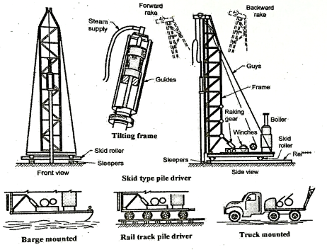
Fig.: Pile driving
- Where it's inconvenient or uneconomical to use pile false or suspended or hanging leads area unit helpful. They carry with it a try of leads braced at the side of short affiliation and area unit command in position by guy ropes or suspended from a jib of a crane. The swinging leads area unit called pendulum leads.
- At times the tower itself may be tipped back or forward for driving rake piles. The chassis provides conjointly for hoisting engines, steam boilers, winches etc. The assembly is either mounted on a base appropriate for operation ashore, on a barge or a car. The rigs used ashore could also be of skid kind or track pile drivers. The mounting can also swivel on the bottom.
- At present, pile drivers’ area unit nearly universally of steel construction and vary from ten m to twenty-five m high to elaborate frames of twenty-five m or a lot of tall, with extension booms, and capable of full rotation and backward or forward raking.
- Recent trend is towards light-weight and simply movable mast-type frames of tabular steel. No matter could also be the kind it's essential to make sure that pile frame remains in its correct position throughout the driving or tilt might end in dislocation of the leads is allowed.
- Alignment of the frame conjointly must be checked to make sure that frame isn't subsidence throughout driving Settlement of frame throughout provides rise to serious risk of breaking pile.
Q7) Explain Static Formulae?
A7)
- The carrying capacity of bored piles can be calculated by static methods. There are some formulae, where soil and the dimensions of the pile and nature of its surface strata in earth are accounted.
- Some of the formulas are having more empirical approach. This type of formulae is particularly suitable for friction piles.
- When bored piles are taken down to some firm bearing stratum like very compact clay, sand, gravel or rock besides friction, end resistance also need to be accounted.
- The value however computed by such formulae often neglects the end resistance.
- Besides often the theory behind these formulae which presumes that frictional resistance increases with depth is also not always true, particularly in case of cohesive soils.
- Therefore, as the cost of piling does not increase with depth so appreciably, it is economical to drive piles, in cohesionless soil, to the maximum depth possible before damage to the pile occurs in order to obtain, the maximum working load on the pile.
- The percentage of load carried by end bearing varies with the pile, type of soil and the end support may not be effective unless the load is sufficiently large. In firm sands and gravels, end bearing can contribute 1/3rd or the total resistance.
- Loose clay provides considerable point bearing whereas the softer clay may provide none. If the pile penetrates through several different strata the friction along the length of the pile does not vary uniformly all along, although in all sands point resistance increases.
- The disturbance of soil is minimum with bored cast-in place piles. The static formula may be expressed in its simple form as-

Where,
Ru = ultimate bearing capacity of the pile
Rb = ultimate point bearing capacity of the pile
Qs =ultimate frictional bearing capacity of the pile (portion acting in friction) and
Ws = weight of pile (often neglected)
- The lowest possible factor of safety with static formulae is 1.5. The basic bearing capacity equation would give more reliable results.

For bearing pile …... (1)
- If the pile tip is embedded in a granular (cohesionless) soil for a depth, the bearing capacity may be estimated as:
 …… (2)
For cohesive soils,  for deep foundation=9
 …... (3)
Where D = Diameter of the pile tip
c = cohesion of soil,
Lp = total penetration of pile
Y = unit weight of soil above the supporting stratum, buoyant weight for the portion below ground alter.
Nc, Nq, N , =bearing capacity factors, value depending on the type of the soil.
h = depth of penetration of pile tip in the supporting layer of granular soil,
Fs= (for cohesionless soils)
And  = angle of wall friction between pile and soil (
 =0.55
=0.55 )
)
k= lateral stress coefficient. (0.6-1.25)
Fs (cohesive soils) = 
 adhesion factor (0.4-0.8)
S =shape factor (1 for straight pile and 1.2 for tapered pile)
Q8) Explain Dynamic Formulae?
A8)
- The bearing capacity of the driven piles can be determined to some extent by dynamic or driving formula.
- A pile driving formula is an attempt to evaluate the resistance of a pile to the dynamic forces applied upon it during the driving and to estimate from this static longitudinal load that the pile can support safely as a part of permanent substructure.
- The use of such dynamic formula generally requires knowledge of certain properties and characteristics of the equipment and the pile, together with the measurement or estimation of various data in the field.
- The most commonly used dynamic formulae are quoted here. For piles driven in fills negative friction needs to be accounted for.
- The dynamic formulae are based, as said above, on the laws governing the dynamic impact of elastic bodies.
- Allowance is made for losses of energy due to the elastic contractions of the pile, driving, cap, and subsoil as well as the losses caused by the inertia of the pile.
Dynamic pile load analysis for driven piles:
- In all pile formulas, pile load is related to the driving energy that causes a measurable penetration of pile into soil.
- Energy E of impact of driving hammer is equated to work done during driving plus the losses associated with driving.
Thus, E =  + losses
Where S = pile penetration
Qdy = dynamic pile load
Loss= energy for additional probable penetration 'C' of pile
E=
Energy for driving is result of weight of hammer, WH falling through drop H and equals WH.H.

Where, WH and Qay is in tonnes,
H is in feet,
S, C is in inches.
ENR formula:
Use Factor of Safety = 6
In SI units 
C = constant
= 2.54 mm steam hammer
= 25.4 mm drop hammer
Modified ENR:

H = drop in m and S, C in mm.
n= coefficient of restitution based on helmet type.
= 0.4 wood cushion on steel.
= 0.5 steel on concrete.
= 0.25 steel on wood.
Hiley's formula:

C = (C₁+C₂ + C3) equal to average elastic compression of pile cap, pile and soil in mm.
C₁ = temporary elastic compression of pile head and cap which ranges form 0 - 10 mm.
C₂ =  compression of pile to be obtained by trial in mm.
C3 = Compression of soil, ground movement in mm.
= 0 for hard soil.
= 2.5-5 mm for other soils
n = efficiency of hammer
Limitations of Dynamic Analysis:
- Dynamic resistance of plastic silts and clays is not reliable.
- Skin friction during driving can be much different from that after the rest period.
- Does not give indication of further settlement.
- Pile load obtained by this analysis are too large or too small compared to load test values.
Q9) Explain in detail pile load test and its limitations?
A9)
- For a test conducted using ken ledge placed directly on the top of pile, it is necessary to balance the load on the top of the pile or piles being tested; when the load is large this is very dangerous arrangement and arrangements are necessary on that the readings of settlement can be taken from a safe distance.
- The kentledge load, which may be pig iron, scrap steel sand bags concrete blocks or water tanks, should be steadily lifted by beams in two directions at right angles as shown in Fig.
- If folding wedges are used, it would be easier to loosen them just before taking a reading so that the load on pile is accurate. If a jack is used working against kentledge, it is necessary to have someone constantly in attendance on the pump to ensure that the load is maintained throughout.
- So long as the kentledge is carefully built, there is no danger to any one working underneath until ultimate load is approached and very accurate readings can be taken even using dial gauges.
- In the bootstrap test where reaction is provided by two adjacent piles, these piles should be spaced at least 1.5 m from the test pile. A typical arrangement of this kind is shown in the Fig.
- Unless specially intended as a pile, the test load is not. An ultimate load. The test load usually applied is one and half to two times the design load and the permissible settlement is not more than 12 mm for a pile that can be allowed in the structure.
- Usually, three test piles distributed over a site where soil conditions are fairly uniform may yield sufficient data, but extra piles may be necessary where soil conditions are not uniform or where the test pile data are dissimilar.
- After a test pile is driven, the soil is given time to adjust. In permeable oil a duration of 3 to 4 day may be enough whereas in clayey soils a month or more is required.
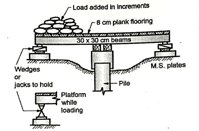
Fig.: platform Load test
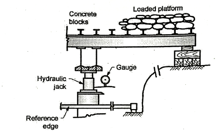
Fig.: jacking against load
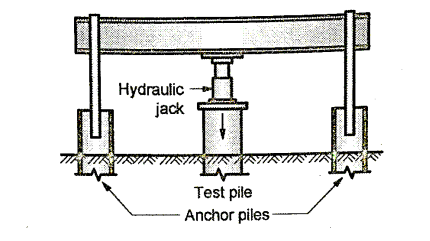
Fig.: Jacking loads against piles
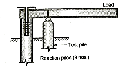
Fig.: Cantilever load test
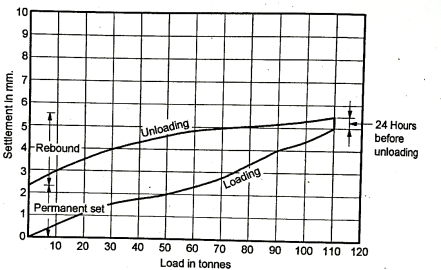
Fig.: Pile load test
- The load is applied to the pile in predetermined increments usually of 5 to 10 tonnes, and the settlement readings are taken before and after every application of the load.
- When the ultimate load or 150 per cent of the design load is reached in both cases the addition of increments is suspended for 24 hours and then the load is reduced at same interval of time as for addition.
- Finally, the permanent set is observed after 24 hours after the whole load is removed. Generally, the piles are tested to the 150 or 200 per cent of the design load with a factor of safety one and half to two depending upon the soil and type of pile.
- If the permanent set is less than 12 mm the pile is accepted as satisfactory one.
- A new approach to pile testing particularly for piles: driven in clay or which have their bearing in sand or gravel (not on rocks) has been put forth by Whitaker and Cooke wherein ultimate bearing capacity is found by a constant rate of penetration.
- This method is particularly suitable to friction piles and to those that are not driven to bear on rock.
Limitations of static pile load test:
- In c- soils, complete consolidation settlement does not take place during short test duration.
- Test is very expensive.
- Test load may indicate only skin resistance while ultimate resistance may be much higher due to additional end bearing.
Q10) Explain cyclic pile load test?
A10)
- When the load bearing capacity of a pile is composed of skin friction and point bearing, separating out the two would help in rationalizing the design of pile foundations.
- By pull out test with a suitable rig friction resistance can be measured. But with cyclic loading the pile carrying capacity can be separated into skin friction and end bearing and the clumsy pull-out test can be avoided.
- Observations for cyclic load test are given in Fig.
- Cyclic loading test comprises of loading the pile to the test load in a progressive manner, but at the addition of every increment the entire load is removed after settlement observations are taken. After noting the elastic rebound, the load with next increment is applied to the pile.
- Cyclic loading test which requires alternate loading and unloading is possible only with hydraulic jack. In order to simulate the effect of future fluctuations of load a cycle of loading and unloading may sometimes be repeated at 5 to 10 minutes intervals, before applying the next higher load.
- Indian Standard 2911-1964 gives details for interpretation of the test results.
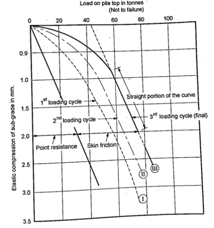
Fig.: Cyclic load test
Q11) Explain about Group action in piles?
A11)
- Building structures to be supported on pile foundations are of the framed type and individual column footings are supported on a group of piles.
- Large groups of vertical piles or with vertical and raked (inclined) piles may be used to support bridge piers, wharf walls, retaining walls etc. In very rare cases singular piles are used. It is, therefore, important to know the behavior of piles in group and the arrangement of piles in a group has to be done according to their type such as end bearing or friction piles and whether precast or cast in situ type.
- The individual reactions of the piles may also dictate upon the spacing of piles may be spaced with varying spacing for obtaining equal pile reactions.
- The bearing capacity of a pile group is less than the capacity of single pile multiplied by the number of piles in the group.
- The safe design capacity of a pile in a group, therefore, is obtained by using an appropriate efficiency factor depending upon whether the piles are end bearing, and the strata on which they bear, or friction piles.
- The number of piles and their spacing can be then readily decided. If the total area covered by the groups is less than about one half the area covered by the structure, individual pile caps are provided for each group and, if it is greater a pile supported raft extending over a full area of the structure is provided.
- In case of rafts a settlement of less than 5 cm is not considered harmful. When the general arrangement of the piled foundations is complete, the individual piles can be designed, taking into account handling stresses, driving stresses and the stresses when pile is in action. Normally in case of end bearing piles driven to rock or similar firm strata, the gross load to be supported by the group decides the number of piles in a group according to the standard or designed load carrying capacity of the piles.
- It may be pointed out here again that the carrying capacity of a group of piles may not be same as individual capacity multiplied by the number of piles in the group. It has been proved by theory and field tests.
- The reduction in value per pile depends on the size spacing and length of piles and their number in the group.
- The reduction factor which may be used in such cases is also known as efficiency.
Q12) Explain settlement of pile groups?
A12)
There is no precise method of estimating the settlement of pile groups. Hence an approximate method is discussed.
Pile Groups in Cohesive Soil:
- The settlement of pile group in predominantly cohesive soil is given by the sum of the immediate of elastic settlement and long-term consolidation settlement of the subsoil.
- The procedure for calculating these settlements are similar to that for raft foundations with appropriate depth corrections.
- However, it is, necessary to determine the load distribution around a pile group in order to obtain the size and depth of the equivalent raft from which the settlement is to be determined.
- Accordingly, total load, Q is assumed to get dispersed from the foundation level at a slope of 4:1 upto the depth of an imaginary raft at depth 2Df/3, as shown in Fig.
- Here, the size of the imaginary raft becomes (B+Df/6)
- (L + Df/6). Thereafter, the load is assumed to get dispersed at a slope of 2:1 into the underlying strata.
- If the pile group passes through a very weak stratum to an underlying hard stratum, the load is assumed to spread at a slope 4:1 on an equivalent raft at a depth 2L /3, where L is embedment of the pile in the stiff stratum.
- Thereafter, a spread of 2:1 may be followed. For a wholly end bearing pile, the load is assumed to get transferred to an equivalent raft at the level of pile tip without any dispersion through the upper strata.
- It is, therefore, necessary to determine the compressibility characteristics of the soil below the depth 2 Df /3. The settlement of the pile group may then be calculated in the usual way.
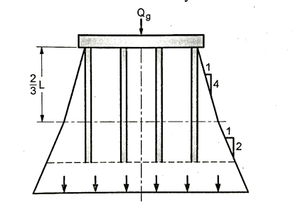
Fig.: Settlement of pile group: Load dispersion
(a) Immediate settlement:

Where q = net pressure on the equivalent raft at depth 2Df/3,
B = width of equivalent raft at depth 2 Df/3,
μ = Poisson's ratio of soil below the depth equivalent raft (may be taken as 0.5),
E = elastic modulus of the soils below equivalent raft= (500-1000)Cu
Ip = influence coefficient, f(L/B), and
 = depth correction factor, f (Df/B, L/B)
(b) Consolidation settlement:
The consolidation settlement of the pile group is obtained from the standard equation,


Where, Cc / (1+e0) and mv, are respectively the compressibility index and the coefficient of volume decrease for the appropriate stress level of the relevant strata,
H is the thickness of strata,
P0 and  p are the in-situ vertical effective stress and the increase of stress in the respective strata, and
 and
and  are respectively the depth and pore-pressure correction factors.
To know the effective depth of soil below the group. The best method is to determine the stress increment ratio Ap / p, at different depths and consider the depth of soil for which  p/p>0.1.
Pile Groups in Cohesionless Soil:
- Pile foundations in sand are not expected to undergo appreciable settlement because of the low compressibility of medium to dense, where piles are usually terminated. Still, if necessary, the settlement of pile groups in granular soil may be determined by using the same methods as given for raft foundations.
- The load distribution in the soil and the equivalent methods raft concept proposed for cohesive soil may also be adopted to obtain the geometry of the problem to be solved.

Where, H = settlement
s = settlement coefficient,
qu= average pressure on the equivalent raft,
N = average SPT value over a depth 2B below the foundation level or Ds, if the depth of cohesionless soil is less than 2B,
Df= depth of equivalent raft, and
B = width of equivalent raft.
The settlement coefficient, s varies with Df/ B as shown in Fig.
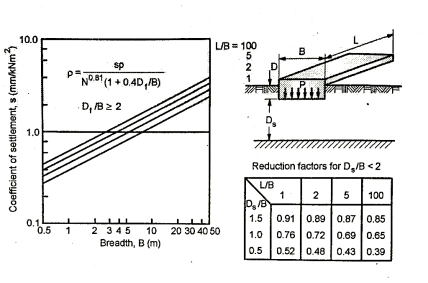
Fig.: Settlement Coefficient, S versus Df/B
Q13) Explain Efficiency of pile groups in clay?
A13)
- Ratio of resisting capacity of pile group to sum of individual capacities of piles in a group is termed as group efficiency, n.
- Group efficiency of friction piles in clays is usually <1, whereas for sands it is> 1.
- i.e., group capacity > sum of individual capacities due to densifying effect of piles driven in sandy soils.
- Pile driving causes increase in shaft resistance due to increase in lateral pressure and increase in the tip resistance due to increase in angle of friction.
- For bearing piles (bearing on hard soil / rock) group efficiency= 1 as pressure bulbs do not overlap.
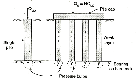
Group efficiency 
Where Qg = group capacity
N = No. Of piles
Qp = single pile load = Qup
For friction piles, group efficiency can be as high as 100% for spacing of piles> 5D and low as 55 % for spacing <2.5 D. While spacing >4.5 D is uneconomical.
Determination of Group Efficiency:
Empirical formulae:
(a) Converse Labarre formula
ɳ=1-

D = Pile diameter
S = Spacing of piles
(b) Los Angeles formula
ɳ=1-
m = No. Of rows of piles
n = No. Of piles in a single row
Q14) What is Negative skin friction?
A14)
- If driven or bored piles are put in during a compressible soil or a fresh placed filling, consolidation of soil develops drag the piles because of relative movement of soil w. r. t piles leading to reduction of pile masses termed as negative skin friction F fatless is down ward drag performing on pile because of down ward movement of encompassing compressible soul relative to pile.
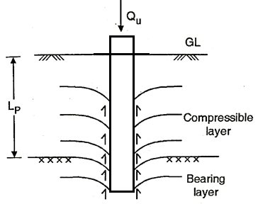
Fig: a) when installed
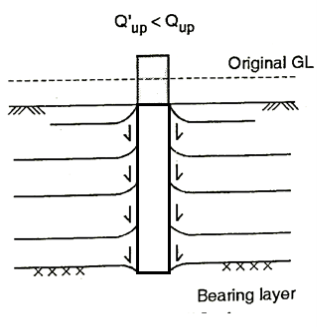
Fig.: b) After consolidation
- As soil consolidates earth fill moves downward developing friction forces AN perimeter of pile tending to hold pile more into ground
- F n can also even be developed by lowering of well water, increasing effective stress inflicting consolidation of soil and resultant settlement and friction force being developed on piles.
Determination:
Magnitude of F n is determined as-
F n =Q s (kin resistance) = A s f s
1. For cohesive soils, F n = p L p S u = (π D) L p S u
Where p = Pile perimeter π D
D p or L p = Length of pile at intervals compressible layer
F s = S u =Un drained shear strength of compressible soil
2. For granular soil
F n = ½ L p2 p  k tan
k tan  <= tan
K = coefficient of lateral pressure
 = unit weight of soil
3. For pile group
(F n) g= N (F n) 1
(F n) g= c L p p +  L p A
L p A
(F n) g= c L p +p  L p A = L p [c p +
  A]
A]
Where A = area enclosed in perimeter p of group of piles
Measure to minimize F n:
Prevention:
- To attenuate this impact, pile spacing ought to be S25 D as reducing pile spacing reduces movement of soil with respect to piles, as a result of the pile cluster acts as one unit and negative skin friction is developed solely on the edge
- Negative skin friction F n is reduced in bored piles if casing is employed quickly throughout driving.
- Negative skin friction in form piles are often reduced by painting the pile surface with hydrocarbon.
Q15) Explain Under reamed pile?
A15)
- Short bored under-reamed pile foundations are particularly suitable for black cotton soil.
- The principle of under-reamed pile foundations is the anchoring of the superstructure at a depth where the volume changes of soil are negligible.
- The anchoring is achieved by enlarging the pile by under-reaming at this zone. The superstructure is then carried on capping beams, which are kept clear of ground.
- The size of the pile depends on the safe load bearing capacity of pile and loading.
- A pile diameter varies from 20 cm but for piles larger than 30 cm boring by manual labour becomes difficult.
- The ratio of the diameter of under-ream to that of the stem may vary from 2 to 3. Depending on the bearing capacity of the soil.
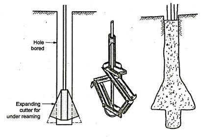
Fig.: Under reamed pile and pilling equipment
- The hole is bored by auger and when it reaches required level the base is enlarged to suitable diameter by a special tool.
- Reinforcement is lowered and the hole is concreted.
- Recently these short-bored piles were provided with another enlarged rim at some height besides the under reaming at base.
- These double under-reamed piles have been lately. Developed at the C.B.R.I. Roorkee and are suggested for two or three storeyed buildings on deep layers of black cotton soils.
Q16) What are component parts of well foundation?
A16)
Various component of wall foundation are shown and are described below
- Cutting edge
- Steining
- Curb
- Concrete seal or bottom plug
- Top Plug
- Well cap
1. Cutting Edge:
- The function of the cutting edge is to facilitate easy penetration or sinking into the soil to the desired depth. As it has to cut through the soil, it should be as sharp as possible, and strong enough to resist the high stresses to which it is subjected during the sinking process.
- Hence it usually consists of an angle iron with or without an additional plate of structural steel. Fig. Shows details of curb with cutting edge. Sinking of well with sharp edge is fast however if strata with boulders is met, then the edge may get damaged.
2. Steining:
- The steining forms the bulk of the well foundation and may be constructed with brick or stone masonry or with plain or reinforced concrete occasionally.
- The thickness of the steining is made uniform throughout its depth. It is considered desirable to provide vertical reinforcements to take care of the tensile stresses which might occur when the well is suspended from top during any stage of sinking.
3. Curb:
- The well curb is a transition member between the sharp cutting edge and the thick steining. It is thus tapering in shape. It is usually made of reinforced concrete as it is subjected to severe stress during the sinking process.

Fig.: Sectional plan and elevation of D shaped well
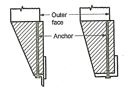
Fig.: Cutting edge with sharp edge and stub nose resp.
4. Concrete seal or bottom plug:
- After the well foundation is sunk to the desired depth so as to rest on a firm stratum, a thick layer of concrete is provided at the bottom inside the well, generally under water. This layer is called the concrete seal or bottom plug, which serves as the base for the well foundation.
- This is primarily meant to distribute the loads on to a large area of the foundation, and hence may be omitted when the well is made to rest on hard rock.
5. Top Plug:
- After the well foundation is sunk to the desired depth, the inside of the well is filled with sand either partly or fully, and a top layer of concrete is placed. This is known as 'top plug'
- The sand filling serves to distribute the load more uniformly to the base of the well, to reduce the stresses in the stening and to increase the stiffness of the well foundation.
- However, as this adds to the weight and load transmitted to the foundation stratum, the engineer has to consider the desirability or otherwise of providing the sand filling from the port of view of bearing power and settlement.
- The top plug and concrete serve to transmit the loads to the base in a uniform manner.
6. Well cap:
- The well cap serves as a bearing pad to the superstructure, which may be a pier or an abutment. It distributes the superstructure load onto the well steining uniformly.
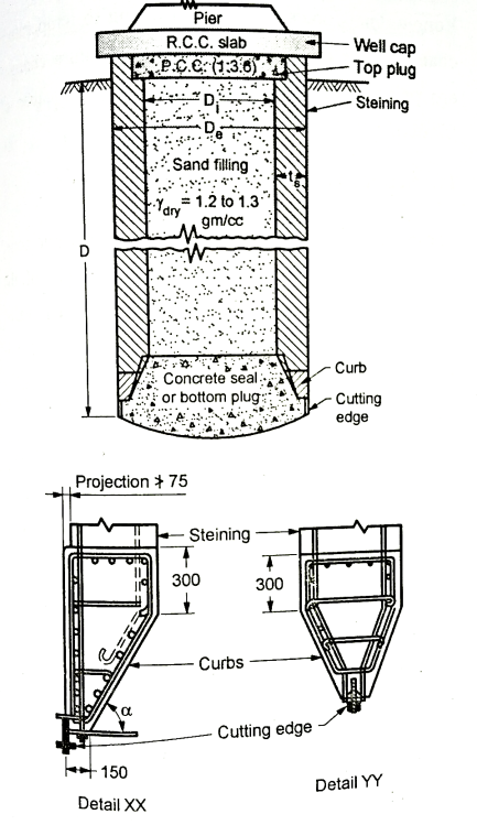
Fig.: Components of well foundation
Q17) Give the Ideas about the force acting on well foundation?
A17)
Forces acting on well foundation are as follows:
1. Dead loads
2. Live loads
3. Impact loads
4. Wind loads
5. Water pressure
6. Longitudinal force.
7. Earth pressure
8. Centrifugal force
9. Buoyancy force
10. Temperature stresses
11. Seismic forces
12. Resultant force
1. Dead Loads:
The weight of the superstructures and self-weight of the well foundation constitute the dead loads.
2. Live Loads:
The live loads in the case of highway bridges are specified by IRC. For design of railway bridges, Indian railways follow,
The Indian Railway Bridge Rules (1963) given by Research, Design and Standards Organization (RDSO), Lucknow of the Ministry of Railway, Government of India.
3. Impact Loads:
The live loads cause impact effect and it is considered in the design of pier cap and bridge seat on the abutment. Impact effect may be ignored for the elements of the well.
4.Wind Loads:
Wind loads acting on, superstructure and the part of substructure located above the water level are calculated based on "Indian Standard Code of Practice for Structural Safety of Buildings - Loading Standards". Wind Loads act on the exposed area laterally.
5. Water pressure:
Water pressure is due to the water current acting on the part of the substructure between the water level and the maximum scour level.
The intensity of Water pressure on piers parallel to the direction of flow is given by
P = K. v²
Where, p = Intensity of Water Pressure (N/m²)
v = Velocity of the water current (m/s),
K = a constant, which depends upon the shape of the well (maximum 788 for square ended piers, and minimum 237 for piers with cut waters and ease-waters).
v is taken to be the maximum at the free surface of flow and zero at the deepest scour level, the variation being assumed to be linear. The maximum value is taken to be √2 times the average value.
A transverse force of 20% of that parallel to the flow is assumed to allow for occasional obliquity of flow.
6. Longitudinal Force:
Longitudinal force occurs due to tractive and braking forces. These are transmitted to the substructure mainly through fixed bearing and through friction on movable bearings. According to IRC code, a longitudinal force of uw is taken on the free bearing and the balance on the fixed bearing, where W is the total reaction and μ the coefficient of friction.
7. Earth Pressure:
The earth pressure is calculated based on one of classical earth pressure theories by Rankine or Coulomb. Passive earth resistance of the soil is taken into account for the stability of foundations below the scour level. The effect of the live load on the abutment on the earth pressure is considered by taking an equivalent height of surcharge.
8. Centrifugal Force:
A centrifugal force is taken to be transmitted through the bearings if the superstructure is curved in plan.
9. Buoyancy Force:
Buoyancy reduces the effective weight of the well in masonry or concrete steining. 15% of the weight is taken as the buoyancy force to account for the porousness.
When the well is founded on coarse sand, full buoyancy equal to the weight of the displaced volume of water is considered. For semipervious foundations appropriate reduction may be made based on the location of water table
10. Temperature Stresses:
Longitudinal forces are induced owing to temperature changes. The movements due to temperature changes are partially restrained in girder bridges because of friction.
11. Seismic Forces:
These are to be considered in appropriate seismic zone. It is equal to a W. Where W is the weight of the component, and at is the seismic coefficient. The value of a depends upon the Zone and is given in IS: 1893. 1975 "Indian Standard Criteria of Earthquake Resistance Design on Structures".
Its value ranges from 0.1 to 0.08. The Seismic Force acts through the centre of gravity of the component. It may act in any one direction at a time. Separate seismic forces are considered along the axis of the pier and transverse to it.
12. Resultant Force:
The magnitude, direction and the point of application of all the applicable forces are found for the worst possible combination. The resultant can be imagined to be replaced by an equivalent vertical force W, and lateral forces, P and Q in the longitudinal and transverse direction of the pier, respectively. The action of Q will be more critical in the consideration of lateral stability of the well.
Q18) Determine the capacity of pile by using following data. Diameter of pile = 600 mm, length = 7m, ¢ = 30°, soil density = 17 kN/m³, c = 20 kN/m², reduction factor,  = 0.5, Nc=65, Nq =35, N
 = 18, factor of safety = 3.
A18)
Given: d = 600 mm, L= 7 m,  = 30°,
  = 17 kN/m², C = 20 kN/m², α = 0.5, Nc= 65, Nq= 35, N
 = 18, FOS = 3
Q =
= 
Qu = 2129.95 KN
Qa= = 709.98
Q19) A square group of 9 piles was driven into soft clay extending to a large depth. The diameter and length of the piles were 30cm and 9m respectively. If the unconfined compression strength of the clay is 90 kN/m2 and the pile spacing is 90 cm centre to centre, what is the capacity of the group? Assume a factor of safety of 2.5 and adhesion factor of 0.75.
A19)
Given: FOS = 2.5, a=0.75, s=0.9, N=9,
C= =
=

Width of pile group, B = 2 (0.9) +0.3= 2.1 m
Qg=5186KN

Individual action
Qg=2835 KN<5186KN
Individual action governs the design
Allowable group capacity= 2835/2.5= 1134 KN
Q20) In a 16-pile group, with 45 cm diameter and c/c spacing of the square group is 1.5 M. If c = 50 kN/m2, determine whether the failure would occur with the pile acting individually or as a group? Neglect end bearing and assume m = 0.7 for shear mobilization. All piles are 10m long.
A20)
Given: N=16, C = 50 kN/m²,  =0.7, L = 10 m
Group action of piles

L=B= (1.5) 3+0.45 = 4.95 m
P = perimeter of pile group = 4 x 4.95 = 19.8
Individual action of piles,


=16
= 7916.8 kN< Qg (group action)
Hence piles will fail when individual pile action is considered.
Q21) Group of 10 piles, 300 x 8 m arranged in 3 rows (3+4+3) are spaced at 1m c/c. Determine the group capacity using different efficiency formulae, if single pile capacity is 300 kN.
A21)
n = 3
m = 3.33
Mn= 10
(i) Converse Labarre's form
ɳ=1-
ɳ=1-
ɳ=85.80%
Qg=85.80×300×10=257.415KN
(ii) Los Angeles form
ɳ=1-
=1-
ɳ=84.03%
Qg=84.03×300×10=252.09KN
(iii) Feld Rule
No. | Number of adjoining piles=reduction number(A) | Reduced units 16-(A) |
1 | 3 | 13 |
2 | 4 | 12 |
3 | 3 | 13 |
4 | 3 | 13 |
5 | 6 | 10 |
6 | 6 | 10 |
7 | 3 | 13 |
8 | 3 | 13 |
9 | 4 | 12 |
10 | 3 | 13 |
Qp=10×16=160 | QR=122 |
ɳ=
Qg=2287.5KN
Q22) A group of piles consists of 15 piles arranged in three rows and five columns. Compute efficiency of pile group by (a) loss-angles formula and (b) field rule. Assume diameter of piles = 300 mm and spacing 0.75m centre to centre.
A22)
Given: n = 3, m = 5
Los Angeles formula,
ɳ=1-
ɳ=71.72%
Feld Rule,
Sr. No | Number of adjoining piles=Reduction number | Reduced units 16-(A) |
1 | 3 | 13 |
2 | 5 | 11 |
3 | 5 | 11 |
4 | 5 | 11 |
5 | 3 | 13 |
6 | 5 | 11 |
7 | 8 | 8 |
8 | 8 | 8 |
9 | 8 | 8 |
10 | 5 | 11 |
11 | 3 | 13 |
12 | 5 | 11 |
13 | 5 | 11 |
14 | 5 | 11 |
15 | 5 | 13 |
 |  |
ɳ=
Q23) Calculate the group efficiency of pile group consisting of 20 piles which are arranged in four rows, if the diameter of pile is 400 mm and spacing is 1 m c/c by using (i) Converse Labbare's formula and (ii) Feld's rule.
A23)
n = 5, m= 4,
(i) Converse Labbare's formula,
ɳ =1-
ɳ =1- ×100
×100
ɳ = 63.83 %
(ii) Feld rule
ɳ=