UNIT 2
Three Phase Circuits
Q1) Explain three phase circuit?
A1) Three phase circuit is the polyphase system where three phases are sent together from the generator to the load.
Each phase is having a phase difference of 120o, that is 120o angle electrically. So, from the total of 360o, three phases are equally divided into 120o each. The power in three phase system is continuous as all the three phases are involved in generating the total power.
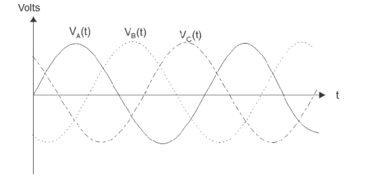
The sinusoidal waves for 3 phase system shown below-
The three phases can be used as single phase each. So, if the load is single phase, then one phase can be taken from the three- phase circuit and the neutral can be used as ground to complete the circuit.
If we arrange three single phase circuit with 120o phase difference, then it will become a three -phase circuit. So, 120o phase difference is must otherwise the circuit will not work, the three- phase load will not be able to get active and it may also cause damage to the system.
In three phase circuit, connections can be given in two types:
Star Connection
In star connection, there is four wire, three wires are phase wire and fourth is neutral which is taken from the star point. Star connection is preferred for long distance power transmission because it is having the neutral point.
When equal current flows through all the three phases, then it is called as balanced current. And when the current will not be equal in any of the phase, then it is unbalanced current.
During balanced condition, no current will flow through the neutral line and hence there is no use of the neutral terminal. But when there will be unbalanced current flow in the three- phase circuit, neutral is having a vital role. It will take the unbalanced current through to the ground and protect the transformer.
Unbalanced current affects transformer and it may also cause damage to the transformer and for this star connection is preferred for long distance transmission.
The star connection is shown below-
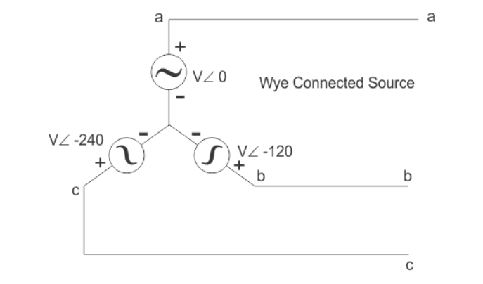
In star connection, the line voltage is √3 times of phase voltage. Line voltage is the voltage between two phases in three phase circuit and phase voltage is the voltage between one phase to the neutral line.
And the current is same for both line and phase.
It is shown as expression below
E line =  E phase and I line = I phase
Delta Connection
In delta connection, there is three wires alone and no neutral terminal is taken. Normally delta connection is preferred for short distance due to the problem of unbalanced current in the circuit. The figure is shown below for delta connection. In the load station, ground can be used as neutral path if required.
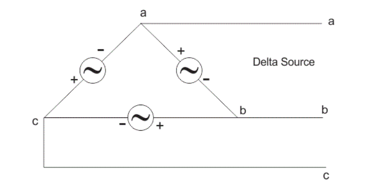
In delta connection, the line voltage is the same as that of phase voltage. And the line current is √3 times of phase current. It is shown as expression below,
E line = Ephase and I line =  I phase
2.Derive the expression for three phase emf equation?
The three- phase power is mainly used for generation, transmission and distribution of electrical power. Power in a single-phase or circuit is given by
P = VI cos ɸ
Where
V is the voltage of single phase i.e Vph
I is the current of single-phase i.e I ph and
cos ɸ is the power factor of the circuit.
In 3 phase circuits (balanced load), the power is defined as the sum of various powers in a three-phase system. i.e.
P = 3 Vph I ph cos ɸ
Power in star connections in a 3 phase circuits is given as
P = 3 VL/  IL cos ɸ -----------(1)
In 3 -phase system, there are three equal voltages or EMFs of the same frequency having a phase difference of 120 degrees. These voltages can be produced by a three-phase AC generator having three identical windings displaced apart from each other by 120 degrees electrical.
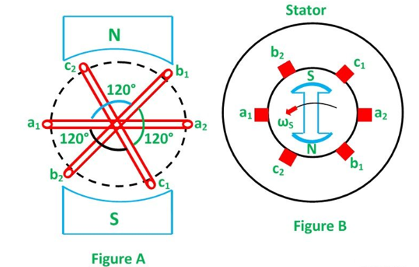
When these windings are kept stationary, and the magnetic field is rotated as shown in the figure A below or when the windings are kept stationary, and the magnetic field is rotated as shown below in figure B, an emf is induced in each winding. The magnitude and frequency of these EMFs are the same but are displaced apart from one another by an angle of 120 degrees.
Consider three identical coils a1a2, b1b2 and c1c2 as shown in the above figure. In this figure a1, b1 and c1 are the starting terminals, whereas a2, b2 and c2 are the finish terminals of the three coils. The phase difference of 120 degrees is maintained between the start terminals a1, b1 and c1.
Now, let the three coils mounted on the same axis, and they are rotated by either keeping coil stationary and moving the magnetic field or vice versa in an anticlockwise direction at (ω) radians per seconds. Three EMFs are induced in the three coils respectively.
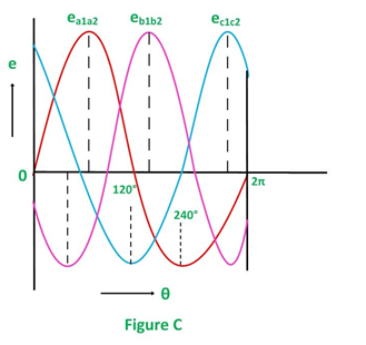
Considering the figure C, the analysis of their magnitudes and directions are given as follows:
The emf induced in the coil a1a2 is zero and is increasing in the positive direction as shown by the waveform in the above figure C represented as ea1a2.
The coil b1b2 is 120 degrees electrically behind the coil a1a2. The emf induced in this coil is negative and is becoming maximum negative as shown by the wave eb1b2.
Similarly, the coil c1c2 is 120 degrees electrically behind the coil b1b2, or we can also say that the coil c1c2 is 240 degrees behind the coil a1a2. The emf induced in the coil is positive and is decreasing as shown in figure C represented by the waveform ec1c2.
Phasor Diagram The EMFs induced in the three coils in 3 phase circuits are of the same magnitude and frequency and are displaced by an angle of 120 degrees from each other as shown below in the phasor diagram:
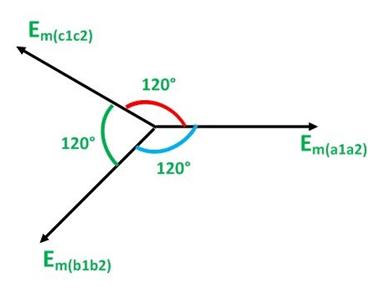
These EMFs of 3 phase circuits can be expressed in the form of the various equations given below:
e a1 a2 = Em sin wt
e b1b2 = Em sin(wt-2π/3) = Em sin (wt -120)
e c1c2 = Em sin(wt-4π/3) = Em sin(wt -240)
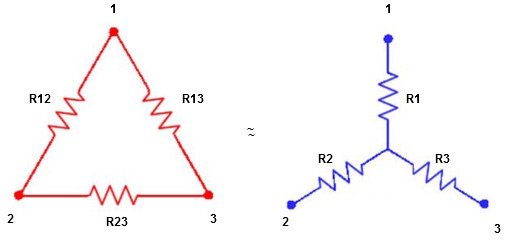
Q2) Explain delta to star conversion ?
A2)
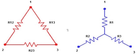
Delta  Star
Star
= R12// (R23 + R13) =R1 + R2
= 
 = R1 + R2
= 

Here let R = R12 + R23 + R13
= 
 R2 + R3

 R1 + R3
Now the 3 equations after equating L.H.S. and R.H.S
R1 + R2 =  …….①
…….①
R2 + R3 =  ……②
……②
R1 + R3 =  …..③
…..③
Now subtract ② and ① on L.H.S. and R.H.S
R2+ R3 – R1 – R2 = 
 R3 – R1 =
  …..④
…..④
Now add equation ④ and ③
R3 – R1 + R1 + R3 = 
2R3 = 

Similarly R1 = 
And R2 = R23 R12/R where R = R12 + R23 + R13
ie star equivalent from delta network is ratio of product of adjacent branches in delta to the addition of all branches in delta.
Q3) Explain the solution to three phase circuits ?
A3) 3Φ system in which three voltages are of identical magnitudes and frequency and are displaced by 120° from each other called as symmetrical system.
Phase sequence:
The sequence in which the three phases reach their maximum positive values. Sequence is R-Y-B. Three colors used to denote three faces are red ,yellow and blue.
The direction of rotation of 3Φ machines depends on phase sequence. If a sequence is changed i.e. R-B-Y then the direction of rotation will be reversed.
Types of loads
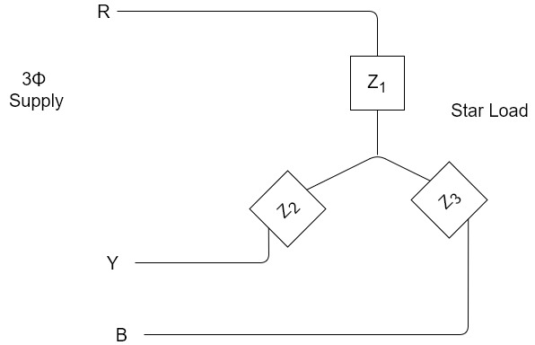
Balanced load:
Balanced load is that in which magnitudes of all impedances connected in the load are are equal and the phase angles of them are also equal.
i.e. 
If.  ≠
≠  ≠
≠  then it is unbalanced load
Q4) Explain its phasor diagram?
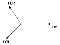
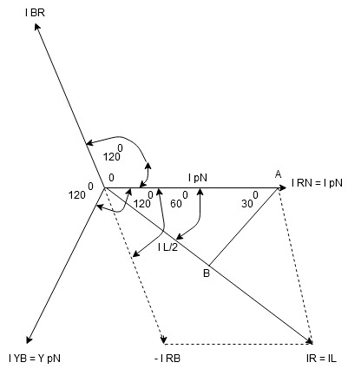
A4) Consider equation ①
Note : we are getting resultant line current IR by subtracting 2 phase currents IRY and IBR  take phase currents at reference as shown
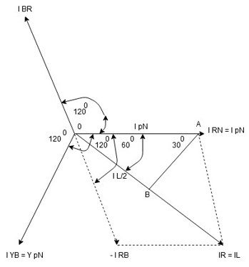
Cos 300 = 
 =
= 

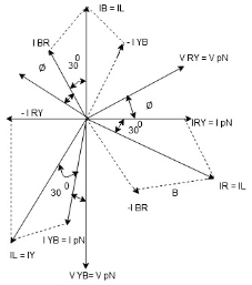
Phase current IYB lags behind VYB which is phase voltage as the load is inductive
Q5) Explain the measurement of power in three phase circuits ?
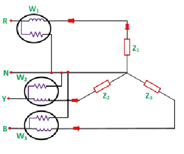
A5) Three Wattmeter method is employed to measure power in a 3 phase, 4 wire system. However, this method can also be employed in a 3 phase, 3 wire delta connected load, where power consumed by each load is required to be determined separately.
The connections for star connected loads for measuring power by three wattmeter method is shown below:
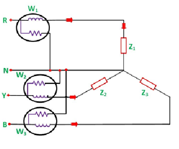
The pressure coil of all the three wattmeters namely W1, W2 and W3 are connected to a common terminal known as the neutral point. The product of the phase current and line voltage represents phase power and is recorded by an individual wattmeter.
The total power in a three-wattmeter method of power measurement is given by the algebraic sum of the readings of three- wattmeter. i.e.
Total power P = W1 + W2 + W3
Where,
W1 = V1I1
W2 = V2I2
W3 = V3I3
Except for 3 phase, 4 wire unbalanced load, 3 phase power can be measured by using only Two Wattmeter Method.
Q6) Explain star to delta conversion ?
A6) Star to delta conversion to final equivalent resistance
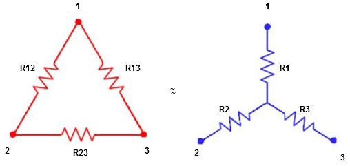
We know that (from delta to star conversion)
R1 =  …….①
…….①
R2 =  …..②
…..②
R1 =  ……③
……③
Multiply ① X ② L.H.S and R.H.S
R1 R2 =  …….④ where
Similarly multiply ② X ③
R2 R3 =  …….⑤
…….⑤
And ③ X①
R1 R3 =  …….⑥
…….⑥
Now add equation ④, ⑤, and ⑥ L.H.S and R.H.S


 ……refer eq. ②
 =
=  +
+  +
+ 
 =
=  +
+ 

(Delta) star star
Similarly R23 = R2+R3 + 
R23 = R1+R2 + 
Q7) Explain the voltage and current relations in star and delta conversions?
A7)

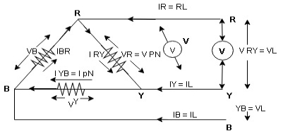
consider a 3 Ø balance delta connected inductive load
Line voltage = VRY = VYB = VBR = VL
Line current = IR = IY = IB = IL
Phase value
Phase voltage = VRN = VYN = VBN = Vph
Phase current = VRN = VYN = VBN = Vph
 for balance delta connected load VL = Vph
 VRV = VYB = VBR = VR = VY = VB = VL = VPh
IR + IRY= IRY
 IR = IRY - IRY … …. ①

Line phase
Similarly apply KCL at node Y
IY + IYB = IRY … …. ②
Apply KCL at node B
IB + IBR = IYB … ….③
PPh = VPh IPh Cos Ø
For 3 Ø total power is
PT= 3 VPh IPh Cos Ø …….①
For star
VL and IL = IPh (replace in ①)
 PT = 3
  IL Cos Ø
 PT = 3
  VL IL Cos Ø – watts
For delta
VL = VPh and IL =  (replace in ①)
PT = 3VL
= 3VL  Cos Ø
Cos Ø
 PT
PT VL IL Cos Ø – watts
total average power
P =  VL IL Cos Ø – for ʎ and
  load
load
K (watts)
Total reactive power
Q =  VL IL Sin Ø – for star
  delta load
K (VAR)
Total Apparent power
S =  VL IL – for star
  delta load
Q8) Convert the following Delta Resistive Network into an equivalent Star Network.
A8)
Q = AC/ A+B+C = 20 x 80 / 20 + 30 + 80 = 12.31 Ω
P = AB/ A+B+C = 20 x 30 / 130 = 4.61 Ω
R = BC / A+B+C = 30 x 80 /130 = 18.46 Ω
Q9) Convert the following Star Resistive Network into an equivalent Delta Network.
A9)
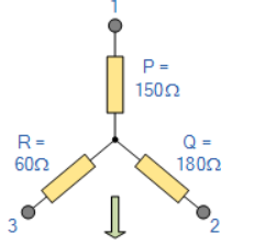
A = QP/R + Q+P = 180x150/60 +180+150 = 780Ω
B = RP/Q + R + P = 60 x 150/180 +60+150 = 260Ω
C = QR/P + Q + R = 180x60/150 + 180 + 60 = 312 Ω
