Module 3
Magnetic Circuits
Q1) What is a magnetic circuit?
A1) A magnetic circuit is made up of magnetic materials having high permeability such as iron, soft steel, etc. Magnetic circuits are used in various devices like electric motor, transformers, relays, generators galvanometer, etc.
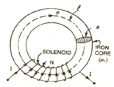
Consider a solenoid having N turns wound on an iron core. The magnetic flux of ø Weber sets up in the core when the current of I ampere is passed through a solenoid.

Let, l = mean length of the magnetic circuit
A = cross-sectional area of the core
µr = relative permeability of the core
Now the flux density in the core material
B = ɸ / a (Weber/m 2)
Magnetising force in the core
H = B / μo μr.
H = ɸ / a μo. μr . AT/m (Amperes turns/meter)
According to work law, the work done in moving a unit pole once round the magnetic circuit is equal to the ampere-turns enclosed by the magnetic circuit.
H l = N l
H = ɸ / a μo μr x l
H = N I
ɸ = N I / l/ a μo μr
The above equation explains the following points:
It shows that the flux increase if the number of turns or current increases and decreases when either of the two quantity decreases. NI is the magnetomotive force (MMF).
Q2) Explain the operation of magnetic field ?
A2) The operation sequence is as follow
2. Interaction of two magnetic field
At the top flux lines produced by the magnet and conductor are in opposite direction to each other and hence cancel each other.
At the bottom individual fields are in same direction they will add each other.

3. Force excreted on the conductor
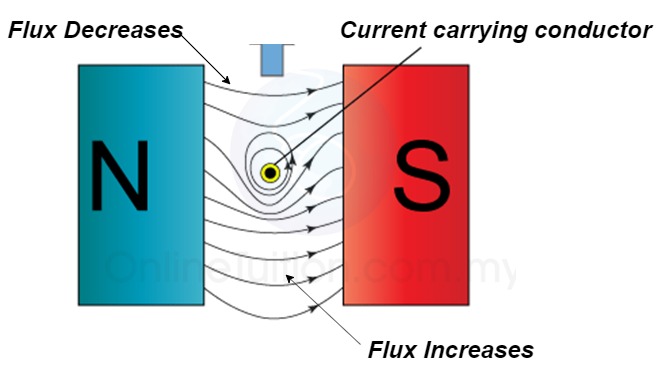
The lines of force on the bottom exert a force on the conductor in the upward direction as shown above.
Hence mechanical force is exerted on the conductor from high flux line area towards the low flux line area (top).
The magnetically of force experienced by the current carrying conductor placed in a magnetic field is given by
F = B I ɺ sin Ɵ newton
Where F = Force exerted
B = Flux density
ɺ = length of conductor
I = current
Ɵ = angle between conductor and magnetic field.
Q3) Explain the following terms:
MMF = No. of turns x current
= N x I
= Ampere Turns
=AT
3. Magnetic flux: The total no of lines of force in a magnetic field denoted by Ø and measured in Weber’s.
4. Magnetic flux density [B] =The flux per unit area measured in a plane perpendicular to the flux is defined as the flux density.
It is measured in tesla [T] and donated by B
B = Tesla / wb /
5. Reluctance - It is defined as the opposition to the flow of flux in a material
Reluctance is denoted by S and measured in AT/wb or SiemensS = ɺ/ μ₀μᵣₐ - AT/wb
It can also be defined as the ratio of (MMF) to the magnetic flux (Ø)
S =  - AT/wb
Q4) Explain Ampere’s law :
A4) Ampere’s Law can be stated as:
“The magnetic field created by an electric current is proportional to the size of that electric current with a constant of proportionality equal to the permeability of free space.”
The equation explaining Ampere’s law which is the final Maxwell’s equation is given below:
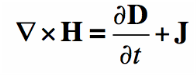
Maxwell’s Equation
According to Ampere’s law, magnetic fields are related to the electric current produced in them. The law specifies the magnetic field that is associated with a given current or vice-versa, provided that the electric field doesn’t change with time.
Q5) Explain Bio-Savart’s law
A5) Biot-Savart’s law is an equation that gives the magnetic field produced due to a current carrying segment. This segment is taken as a vector quantity known as the current element.
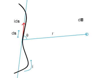
Consider a current carrying wire ‘i’ in a specific direction as shown in the above figure. Take a small element of the wire of length ds. The direction of this element is along that of the current so that it forms a vector i ds.
To know the magnetic field produced at a point due to this small element, one can apply Biot-Savart’s Law. Let the position vector of the point in question drawn from the current element be r and the angle between the two be θ. Then,
|dB|=(μ0/4π)(IdlsinΘ/r2)
where
μ0 is the permeability of free space and is equal to 4π × 10-7 TmA-1.
The direction of the magnetic field is always in a plane perpendicular to the line of element and position vector. It is given by the right-hand thumb rule where the thumb points to the direction of conventional current and the other fingers show the magnetic field’s direction.
Q6) What is a magnetic field?
A6) A magnetic field is a vector field in the neighbour hood of a magnet, electric current, or changing electric field, in which magnetic forces are observable. A magnetic field is produced by moving electric charges and intrinsic magnetic moments of elementary particles associated with a fundamental quantum property known as the spin. Magnetic field and electric field are both interrelated to each other and are components of the electromagnetic force, one of the four fundamental forces of nature.
Q7) Explain B-H characteristics and hysteresis loss?
A7) Hysteresis is the lagging of the magnetization of a ferromagnetic material behind the magnetizing force H.
By using a graph having B-H coordinates, we can plot the hysteresis characteristics of a given ferromagnetic material. Such a curve is plotted in the following figure and called a hysteresis loop. By periodically reversing a magnetizing force, we can plot the changing values of B within the material.
The hysteresis loop is a B-H curve under the influence of an AC magnetizing force. Values of flux density B are shown on the vertical axis and are in Tesla. Magnetizing force H is plotted on the horizontal axis.
In above figure, the specimen is assumed to be unmagnified, and the current is starting from zero in the center of the graph. As H increases positively, B follows the red dotted curve from origin to saturation point a, indicated by Bmax.
As H decreases to zero, the flux follows the curve ab and drops to Br which indicates the retentively or residual induction. This point represents the amount of flux remaining in the core after the magnetizing force is removed.
When H starts in the negative direction, the core will lose its magnetism, as shown by following the curve from point b to c. The amount of magnetizing force required to completely demagnetize the core is called the coercive force and is designated as –Hc in the figure.
As the peak of the negative cycle is approached, the flux follows the portion of the curve labeled cd. Point –Bmax represents saturation in the opposite direction from Bmax . From point d, the – H value decreases to point e, which corresponds to a zero magnetizing force. Flux –Br still remains in the core.
A coercive force of +Hc is required to reduce the core magnetization to zero. As the magnetic force continues to increase in the positive direction, the portion of the loop from point f to a is completed. The periodic reversal of the magnetizing force causes the core flux to repeatedly trace out the hysteresis loop.
Q8) Explain series and parallel magnetic circuit?
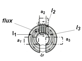
A8) Series Magnetic Circuits
Derivation of series magnetic current with air gap
In series magnetic circuit flux  is same in each part of circuit
Consider a composite magnetic circuit made from different material of lengths ɻ1,ɻ2, and ɻ3 cross sectional area a1, a2 And a3 and relative permeability’s  1 ,
1 ,  2 ,
2 ,  3 resp. with an airgap of length ɻɡ
Parallel Magnetic Circuits
A magnetic circuit which has more than one path for flux called parallel magnetic circuit
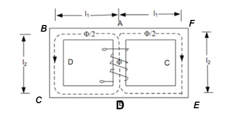
Mean length ABCDA = ɻ₁, and ADEFA = ɻ₂
Mean length path for central limb = ɻc
Reluctance ABCDA = S1, ADEFA = S2
And central limb = SC
Now total mmȴ = N 
 i.e. mmf =
Q9) Explain demagnetization?
A9) Demagnetization or Degaussing
The process by which the magnetization within the ferromagnetic materials is reduced to zero by exposing it to a strong alternating magnetic field that is gradually reduced to zero.
To demagnetize any magnetic material, we must reduce its residual magnetism Br to zero. This can be done by connecting a suitable coil to a source of alternating current and placing it close to the object to be degaussed. Slowly moving the coil and object away from each other, causes the hysteresis loop to become progressively small. Finally, a point is reached where the loop is reduced to zero and no residual magnetism remains.
Q10) What are the applications of magnetic circuits?
A10) Magnetic circuit guides flux to an air gap
This provides field for the voice coil
Playback heads on tape recorders VCRs and disk drives pick up the varying magnetic field and convert it to voltage


