Unit 2
Application of Thermodynamics
Question 1) Explain the difference between 2 stroke and four stroke engine?
Answer 1)
Difference Between Two Stroke and Four Strokes | |
Two Strokes | Four Stroke |
| It has two revolutions of the crankshaft during one power stroke |
ii. It generates high torque | It generates less torque |
iii. Its uses port for fuel’s outlet and inlet | It uses valves for outlet and inlet of a fuel |
iv. Its engines result in lesser thermal efficiency | Its engines result in higher thermal efficiency |
v. It has a larger ratio in terms of power to weight | It has a lesser ratio in terms of power to weight |
vi. It generates more smoke and shows less efficiency | It generates less smoke and shows more efficiency |
vii. Requires more lubricating oil as some oil burns with the fuel | Requires less lubricating oil |
viii. Due to poor lubrication, more wear and tear occurs | Less wear and tear occurs |
ix. Engines are cheaper and are simple for manufacturing | Engines are expensive due to lubrication and valves and are tough to manufacture |
x. Engines are basically lighter and are noisy | Engines are basically heavier because its flywheel is heavy and are less noisy |
Question 2) Explain the difference between compressed ignition engine or Diesel engine and spark ignition engine or Petrol engine?
Answer 2)
S.no | Parameter | SI Engine | CI Engine | ||||
1. | Definition | It is an engine in which the spark is used to burn the fuel. | It is an engine in which heat of compressed air is used to burn the fuel. | ||||
2. | Fuel used | Petrol is used as fuel. | Diesel is used as fuel. | ||||
3. | Operating cycle | It operates on Otto cycle. | It operates on Diesel cycle. | ||||
4. | Compression ratio | Low compression ratio.(6 to 10) | High compression ratio.(15 to 25) | ||||
5. | Thermal efficiency | Low thermal efficiency because of low compression ratio .Up to 26 %. | High thermal efficiency because of high compression ratio up to 40%. | ||||
6. | Method of ignition | Spark plug is used to produce spark for the ignition. | Heat of compressed air is used for the ignition. | ||||
7. | Engine Speed | High speed engines. | Low speed engines. | ||||
8. | Pressure generated | Low pressure is generated after combustion. About 10 bar | High pressure is generated | ||||
9. | Constant parameter during cycle | Constant volume cycle. | Constant pressure cycle. | ||||
10. | Intake | Air + fuel. | Only air. | ||||
| Weight of engine | Si engine has less weight. | CI engine are heavier. | ||||
12. | Noise production | It produces less noise. | It produces more noise. | ||||
13. | Production of hydrocarbon | Less Hydrocarbon is produced. | More hydrocarbons is produced. | ||||
14. | Starting | The starting of SI engine is easy. | The starting of CI engine is difficult. | ||||
15. | Maintenance cost | Low | High | ||||
16. | Vibration problem | Less | Very High | ||||
17. | Cost of engine | Less cost | High cost | ||||
18. | Volume to power ratio | Less | High | ||||
19. | Fuel supply | carburettor | Injector | ||||
20. | application | It is used in light commercial vehicles like motorcycle, cars. | It is used in heavy duty vehicles likes bus, trucks, ships etc. | ||||
Question 3) Explain valve timing diagram of two stroke S.I engine?
ANSWER 3) In the valve timing diagram, as shown we see that the expansion of the charge (after ignition) starts as the piston moves from TDC towards BDC.
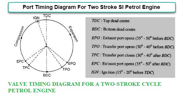 Valve timing diagram for 2 stroke petrol engine
Question 4) Explain valve timing diagram of four stroke C.I engine ?
ANSWER 4) In the valve timing diagram as shown we see that the inlet valve opens before the piston reaches TDC; or in other words while the piston is still moving up before the beginning of the suction stroke.
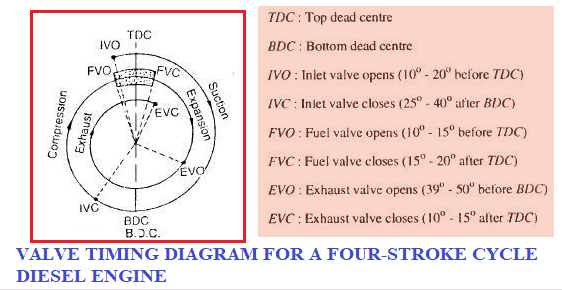
Valve timing diagram for 4 stroke CI Engine
Question 5) Explain different kind of thermal efficiency in internal combustion engine?
Answers 5) There are different kind of efficiency are there
Indicated power (I.p): brake power + friction power
The indicated power (I.P.) of the engine can be calculated as follows:
I..P. = (pm x 105 x L. x A x N x n x k )/60
Pm = Inicated mean effective pressure in bar
L = Length of stroke in meter
A = Piston areas in m2
N = Speed in R.P.M.
n = Number of working stroke per minute.
n = 1 for two stroke engine
n= 1 / 2 for four stroke engine
k= number of cylinders
ii. Brake power (B.P): The power available at crankshaft is called brake power. It is measured by means of brake mechanism either Prony or rope brake.
For Prony brake = 2 Π N T / 60 Watt
For rope brake =(w-s) Π (D+d)N / 60
iii Mechanical efficiency : it is ration of brake power to indicated power
Efficiency = B.P / I.P
iv Indicated thermal efficiency : It is the ration of indicated work done to the energy supplied by the fuel .
η (ith)= I.P (KJ/s)/ energy in fuel per second (KJ/s)
= I.P / mf x cv
V Brake thermal efficiency: It is the ratio of power obtained at shaft to the energy supplied by fuel.
η (b.t.e)= B.P (KJ/s)/ energy in fuel per second (KJ/s)
= B.P / mf x cv
Vi Air standard efficiency: It is the ratio of work output to heat input
For petrol η = 1- 1/ ry-1
For diesel η = 1- 1/ ry-1 [ py-1 / y(p-1) ]
Where p = cut off ratio = v3 / v2 .
Question 6) In an air standard Otto cycle, the compression ratio is 7 and the compression begins at 35oC and 0.1 MPa. The maximum temperature of the cycle is 1100oC. Find
(a) The temperature and the pressure at various points in the cycle,
(b) The heat supplied per kg of air,
(c) Work done per kg of air,
(d) The cycle efficiency and
(e) The MEP of the cycle
Answer 6) Given T1=35oC=308 K
P1=0.1 Mpa
T3=1100oC=1373 K
r=v1/v2=7
(a) the temperature and the pressure at various points in the cycle,
we know that P2/P1 = (V1 /V2)y = 71.4
Hence, P2=1524 k Pa
We also know that T2 / T1 = (V1/V2) y-1 = 71.4
We get T2=670.8 K
For process, 2-3, P2V2 / T2 = P3V3 / T3
P3 = T3 P2 /T2
P3 = 1373 X 1524 / 670.8
P3 = 3119.34 kPa
Process 3-4 is isentropic T3/T4 = (V4 /V3)y-1 = 71.4-1
T4 = 1372 / 2.178
T4 =630.39 K
(b) the heat supplied per kg of air,
Heat input = Qin= cv(T3-T2)
=0.718(1373–670.8)
= 504.18 kJ/kg
Heat rejected = Q out= cv(T4-T1)
=0.718(630.34–308)
=231.44 kJ/kg
(c) work done per kg of air,
The network output Wnet=Qin-Qout
The network output, Wnet=Qin-Qout
=272.74 kJ/kg
(d) the cycle efficiency
Thermal efficiency, ηth otto=Wnet/Qin
=0.54 =54 %
Otto cycle thermal efficiency, ηth,otto =1-1/rγ-1
= 1-1/70.4 = 0.54 or 54 %
v1=RT1/P1 =0.287 x 308 / 100=0.844 m3/kg
(e) the MEP of the cycle
MEP = Wnet/(v1–v2) = 272.74/v1 (1-1/r)
=272.74/0.844(1-1/7)
=360 kPa
Question 7) Explain classification of IC engine?
Answer 7) Classification of Internal Combustion (IC) Engine:
Internal combustion engines may be classified on the basis of:
Question 8) What is carburettor?
Answer 8) Petrol engines are designed to take in exactly the right amount of air so the fuel burns properly, whether the engine is starting from cold or running hot at top speed. Getting the fuel-air mixture just right is the job of a clever mechanical gadget called a carburettor: a tube that allows air and fuel into the engine through valves, mixing them together in different amounts to suit a wide range of different driving conditions.
The carburettor is called the 'Heart' of the automobile, and it cannot be expected that the engine will act right, give the proper horse-power, or run smoothly if its 'heart' is not performing its functions properly.
Question 9) The following data was recorded during testing of a TWO STROKE gas engine:
Diameter of the piston d= 150 mm
Stroke length L= 180 mm
Clearance volume Vc = 0.89 litre
RPM of the engine N = 300
Indicated mean effective pressure pm= 6.1 bars
Gas consumption m. = 6.1 m3/h
Calorific value of the gas (fuel) CF = 17000 kJ/m3
Determine the followings:
a) Air Standard Efficiency
b) Indicated power (IHP)developed by the engine
c) Indicated thermal efficiency of the engine
Answer 9)
Swept volume Vs = πd2L/4 = π(0.150)2 x 180/4 = 0.00318 m3
Clearance volume Vc= 0.00089 m3
Total volume = Swept volume + clearance volume
= 0.00318 + 0.00089 = 0.00407 m3
Compression ratio γ = Total volume/Clearance volume
= 0.00407/0.00089 = 4.573
a) Air standard Efficiency
η = 1 –1/(r)γ—1 = 1—1/(4.573)1.4—1
= 0.456 = 45.6 %
b) Indicated power IHP = 100 pLAN/60
When p is in bars
= 100 x 6.1x 0.180 x [π (0.150)2 /4] x 300 / 60
= 9700 W
(c ) Indicated Thermal Efficiency
ηit = Indicated power in (kJ/s)/Heat supplied in (kJ/s)
= (9700/1000)/ (6.1 x 17000/3600)
= 0.3367 = 33.67 %
Question 10)
A FOUR STROKE petrol engine have given data below
Air fuel ratio 15.5: 1
Calorific value of fuel 16000 kJ/kg
Air Standard Efficiency: 53%
Mechanical Efficiency: 80 %
Indicated Thermal Efficiency: 37 %
Volumetric Efficiency: 80 %
Stroke/bore ratio: 1.25
Suction pressure: 1 bar
Suction Temperature: 270C
RPM: 2000
Brake Power: 72 kW
Calculate the followings:
a) Brake specific fuel consumption
b) Bore and stroke
Answer 10)
Find compression ratio from air standard efficiency
η = 1 –1/(r) γ—1
0.53 = 1 –1/(r) 1.4—1
r = 6.6
IHP = BP/Mechanical efficiency = 72/0.80
= 90 kW
ηit =IHP/(Specific Fuel Consumptions x Cal value)
0.37 = 90/sfc x 16000
sfc is specific fuel consumption
sfc = 0.0152 kg/s
a) Brake specific fuel consumption
Brake sfc = sfc IHP/BP
= 0.0152/72
=0.00021 kg/s /kW
Brake sfc = 0.7601 kg/kWh
b) Bore and stroke
Bore and stroke of the engine
Mass of air fuel mixture/kg of fuel = 15.5 +1 = 16.5
Mass of fuel supplied to the engine = 0.0152 x 16.5 = 0.2508
Volume of air fuel mixture = mRT/p
=0.2508 x 287 × 300/ (1×10⁵)
V = 0.2159 m3/s
Swept volume = volume of mixture supplied/vol efficiency
Vs = 0.2159/0.80= 0.2699
Vs = (πd2L/4) n x (rpm/2) /60
Where n is the number of cylinders
= (πd2 x 1.25 d/4)n rpm/120
d= 0.152 m= 152 mm
L = 190 mm


